
Generic1


Features
- Comparative output, clean signal, good waveform, strong driving ability, more than 15mA.
- Working voltage: 3.3V to 5V
- Output form: digital switch output (0 and 1)
- Equipped with fixed screw hole, easy to install
- PCB board size: 32mm x 14mm
- Uses the LM393 wide voltage comparator
When the VCC and GND are connected, the power indicator will light up.
Put the module on the desktop, adjust the blue potentiometer on the board until the on-board switch indicator lights up, and then slightly turn back the potentiometer untill the indicator light turns off. Hit the desktop with your hand so the vibration shocks the sensor, the indicator light will go on. Vibration stops, indicator light will turn off.
Raspberry Pi Python example

LEARN ABOUT ELECTRICITY – Provide a fun learning experience for inquisitive minds

TB6600 is an easy-to-use professional stepper motor driver, which could control a two-phase stepping motor. It is compatible with Arduino and other microcontrollers that can output a 5V digital pulse signal. TB6600 arduino stepper motor driver has a wide range power input, 9~42VDC power supply. And it is able to output 4A peak current, which is enough for the most of stepper motors.
The stepper driver supports speed and direction control. You can set its micro step and output current with 6 DIP switch. There are 7 kinds of micro steps (1, 2 / A, 2 / B, 4, 8, 16, 32) and 8 kinds of current control (0.5A, 1A, 1.5A, 2A, 2.5A, 2.8A, 3.0A, 3.5A) in all. And all signal terminals adopt high-speed optocoupler isolation, enhancing its anti-high-frequency interference ability.
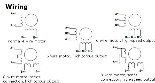
As a professional device, it is able to drive 57, 42-type two-phase, four-phase, hybrid stepper motor.
Features
- 9V-40V DC power supply
- H-bridge bipolar constant phase flow driver
- The maximum output current is 4.0A (eight optional)
- Up to 32 segments of six kinds of sub-modes available
- Input signal high-speed photoelectric isolation
- Standard common anode single pulse interface
- Offline keep function
- Semi-enclosed chassis can adapt to a more demanding environment
- Provide energy saving semi-automatic current lock function
- Built-in thermal protection and over-current protection
Specifications
- Voltage: up to 50V
- ON resistance (upper lower) = 0.4 Ω
- Forward and reverse rotation control
- 5 kinds of sub-modes selectable (1/1, 1/2, 1/4, 1/8, 1/16 step)
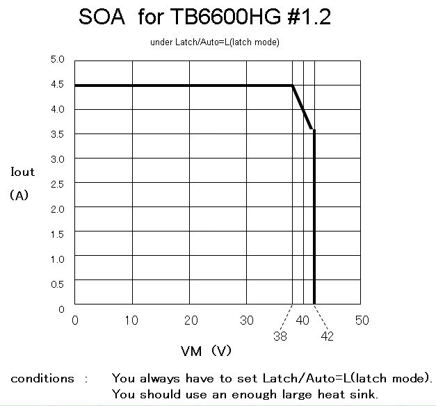
- Output current: IOUT = 5.0A (peak within 100ms)
- Rated output: IOUT = 4.5 A
- Input pull-down resistor: 100 KΩ
- Current output alarm pin: Ialert = 1mA
- Monitor output pin (MO): Imo = 1mA
- With reset and enable pins
- With a standby function.
- Breaking the traditional single-supply
- Built-in thermal protection (TSD) circuit
- Built-in voltage protection (UVLO) circuit
- Built-in over current detection (ISD), the circuit
Note:
This driver is the upgraded version TB6600, heightening segment to 32 subdivision, suitable for high segmentation applications.
For step motor: 42, 57, 86 type 2 phase 4 phase (4 / 6 / 8 line)
What's in the box?
1 x TB6600 Stepper Motor Driver Controller
Resources
https://danielwilczak101.medium.com/control-a-stepper-motor-using-python-and-a-raspberry-pi-11f67d5a8d6d
https://www.instructables.com/Raspberry-Pi-Python-and-a-TB6600-Stepper-Motor-Dri/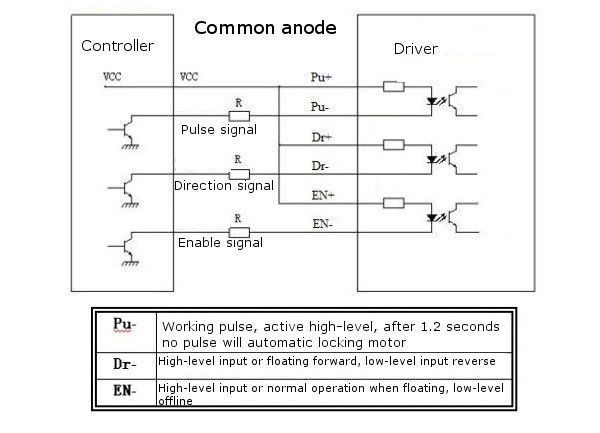

The LiitoKala Lii-402 Smart Charger for Lithium Ion and NiMH batteries is the perfect bench mate to keep your radios, robotics and flashlights running at peak efficiency. In a sea of endless chargers for sale, we have found one that will meet and exceed the needs of many consumers.
Specifications
Product name: Liitokala Lii-402 Micro USB 4Slots Battery Charger
Input : Micro USB DC 5V/2A
Output
- 1.42V
- 4.2V±0.05V
- 3.65±0.05V
- 4.35±0.05V
Current
- 2000mA*1
- 1000mA*2
- 700mA*3
- 500mA*4
Constant voltage, cut-off current: less than 100mAh
Standby current: less than 15mAh
Compatible with
Ni-MH/Cd
AA/AAA/A/SC Sizes
3.7V Li-ion battery including
26650,22650,26500,18650,18490,17670,17500,16340,14500,10440
Size: 112mm x 90mm x 30mm (L x W x H)
Weight: 150 grams (incl. micro cable)
USB Output function
1. 0pen-circuit voltage of USB output : 4.9-5.3V; and the 4th slot is fixed for the USB discharge power source
2. Output current: 1000mAh
3. Open circuit current: <1mAh
4. The corresponding voltage is 4.75-5.25V under 1000mAh current
5. Cut-off voltage for discharge protection: 3.0±0.1V
1 x Liitokala Lii-402 Micro USB 4Slots Battery Charger
1 x USB micro B male to USB A male Cable
You will also need.....
power supply for this charger

The TB6560 stepper motor control circuit is the most commonly used current circuit, which can control a 2 phase motor (10 – 35VDC) with a maximum output of 3A.
Specifications
- Size: 75mm x 50mm x 35mm (L x W x H)
- Rated maximum output: ± 3A, peak 3.5A
- Working voltage: DC 10V-35V
- Recommended to use a switching power supply: DC24V power supply
- Subdivision: whole step, half-step, step 1/8, 1/16 step, a maximum of 16
- Subdivisions.
Features
- Using the Toshiba TB6560AHQ new original chip with low voltage shutdown, overheating stop and over current protection circuit to ensure optimal performance.
- For two-phase within 42, 57 stepping 3A / four-phase / of line four / six-wire stepper motor, and is not suitable for more than 3A stepper motor.
- Automatic half current function.
- 6N137 high-speed optical coupling, guarantee high speed without losing step.
What's in the box?
1 x TB6560 1 axis driver board
Usage Examples
How Much Power Does my Fridge Use - with the Battery connected to the SOURCE side and Car Fridge (or other accessory) connected to the LOAD side. The Watt Meter shows the current into the Fridge, voltage and power at the battery and accumulates the Ah and Wh while the fridge is running.
How much charge is going into my battery - With a battery charger (or alternator) connected to the SOURCE side and the aux battery connected to the LOAD side, the Watt Meter shows the charging current into the battery, the voltage and charging power at the battery and accumulates the charge (Ah) and energy (Wh) into the battery.
What is the output of my solar panel - With a solar panel connected to the SOURCE side and solar regulator connected to the LOAD side, the Watt Meter shows the charging current into the regulator, the voltage and charging power at the solar panel and accumulates the charge (Ah) and energy (Wh) into the regulator.
How much charge is my solar panel putting into my battery - Now with a solar regulator connected to the SOURCE side and battery connected to the LOAD side, the Watt Meter shows the charging current into the battery, the voltage and charging power at the regulator and accumulates the charge (Ah) and energy (Wh) into the battery.
Specifications
| Item Name | Watt Meter and Power Analyzer |
| Item NO. | FT08 |
| Operation Voltage | 4.8V-60V |
| Measures Range | 0-130A, resolution 0.01A; 0-60V, resolution 0.01v; 0-6554W, resolution 0.1w; 0-65Ah,resolution 0.001An; 0-6441Wh,resolution 0.1Wh; |
| LCD | 16 x 2, backlit LCD display |
| Size | 85 mm x 43 mm x 25 mm (3.35 in x 1.69 in x 0.98 in) |
| Weight | 82g |
| Colour | Black |
What's in the box?
1x 130A High Precision Battery Watt Meter And Power Analyzer
Resources
English Manual please click here

4. This is an entry level measuring solution. Do not expect 100% accuracy.
| Product Type | PZEM-022 |
| Accuracy | 1.0 grade |
| Display Size | 51mm x 30mm |
| Product Size | 89.6mm x 49.6mm x 24.3mm |
| Weight | 150g(with split CT) |
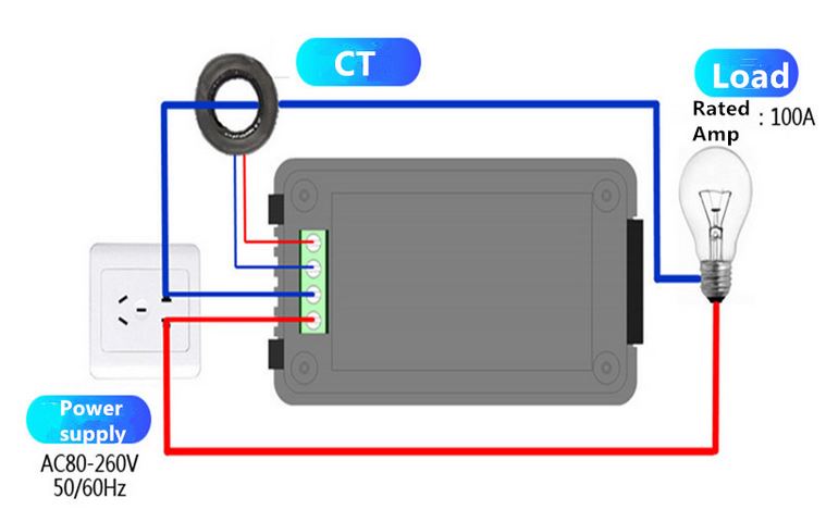
| Test Range | 1. Voltage: 80~260V 5. Frequency: 45~65Hz 6. Power factor: 0~1PF |
| Function | 1. Electrical parameter measurement function (voltage, current, active power, energy, frequency, power factor) 2. Overload alarm function (over power alarm threshold, backlight and power flashing to alarm). 3. Power alarm threshold preset function (can set power alarm threshold). 4. The energy can be reset use the key. 5. Store data when power off. 6. Large-screen LCD 7. Backlight function. |
What's in the box?
1 x CT
Resources
FAQ
Why is the test data wrong? Voltage * Current = Power, But power is less than the actual test voltage * Current, Why is that?
Answer: There are three types of power:
Active Power (P represents / unit W)
Reactive power (Q represents / unit Var)
Apparent power (S represents / unit VA)
Here we only talk about Active Power, for others, please google it:
P = U * I * cosφ, cosφ it represents the power factor, purely resistive load (Such as incandescent, heater, etc.) the power factor is generally close to 1,Between the inductive and capacitive load load power factor 0-1. So purely resistive load test time, P is substantially equal to or close to U * I. When Inductive or capacitive load test (Such as refrigerators, washing machines, televisions, computers, etc.) P<U*I, As for how much to keep the power factor related to the specific, Different for each appliance power factor.

Know how much rain you got overnight with this digital wireless rain station
Features
- Outdoor wireless sensor (range up to 100 meter)
- Detail display of rainfall data in 1hour, 24hour, week, month
and total since last reset(user selectable in inch or mm) - Indoor and outdoor temperature (°F to °C)
- Time and date with manual setting option
- 12 /24 hour time mode
- Calendar
- Time zone setting
- Time alarm
- Free standing
Specifications
- Rainfall display range: 0 to 19,999mm
- Outdoor temperature range: -40 ~ 65°C (-40°F to 149°F)
- Indoor temperature range: -9.9 ~ 60°C (-15.8°F to 176°F)
- Temperature accuracy: ±1.0°C5) Power requirements:
a) Receiver: 2 x "AA" alkaline batteries (not included)
b) Rain gauge: 2 x "AAA" alkaline batteries (not included) - Transmission range: up to 100meters( 330feet)
- Transmission frequency: 433MHz
What's in the box?
1 x Rain Gauge
1 x Receiver
1 x User Manual
2 x Screws

Specifications
- Type:Field-Effect Transistor
- Brand Name: International Rectifier
- Package Type: Throught Hole
- Model Number: IRFZ44NPBF
- TO-220AB: MOSFET N-Channel, Metal Oxide
- 55V 49A: FETs - Single
- Mosfet Type : N-channel
- Current Rating : 49A
- Rds (On) : 17.5mΩ
- Voltage Rated : 55V
What's in the box?
1 x IRFZ44N Transistor
Resources
Introduction to Transistors
Different Types of Transistors and Their Working

Features
- Name: Arduino MEGA2560 R3 DIY acrylic case
- Dimensions: 118 x 72 x 18mm
- Weight: 72g
- Material: A level acrylic
- For Arduino MEGA2560 R3 Development Board only
Please Note: Arduino Mega is not included. Don't forget to remove the protective film from the acrylic parts.
What's in the box
1 x Transparent Acrylic case

Features
- Total length: about 250M
- Wire type: 30AWG
- Single core wire outer diameter: 0.55mm
- Copper core diameter: 0.25mm.
- Temperature: 80 degrees, single-strand copper core crossing tin, with antioxidant effects.
- Colour: Red
What's in the box?
1 x Red wire wrap

Specifications
- Size: 40mm x 40mm x 10mm
- Voltage: DC 24V 0.1A
- Cable length: 200mm
- Application: For 3D Printer Ender-3
What's in the box?
1 x Creality 3D® cooling fan

Features:
- Opening size: 13x13mm
- Rated input current (RMS): 10% - 120% of that is 3A - 36A
- Output voltage(RMS): linear output. When the input current is 30A, the output voltage is 1V
- Linearity: ± 3%
- Output connectors: 3.5mm standard three-pin plug
- Lead length: 1 m
What's in the box?
1 x Current sensor
This sensor is perfect for use with our Raspberry Pi RPICT3T1 current and temperature sensor board.

This is a split-core current transformer which is used as an AC current sensor. It is popularly used for current measurement, monitoring and protection for AC motors, lighting equipment, air compressors, home automation etc.
Features
- Opening size: 13 x 13mm
- Rated input current (RMS): 10% - 120% of that is 1A~100A
- Output voltage(RMS): linear output. when the input current is 100A, the output voltage is 1V
- Linearity: ± 3%
- Output connectors: 3.5mm standard three-pin plug
- Lead length: 1m
What's in the box?
1 x Split-Core Current sensor

Specifications
- Model: PJ-392
- Size(LxWxH): Approx. 22.5mmx 8mm x 8mm/ 0.89x3.15x3.15"
What's in the box?
1 x Stereo Headphone Audio Video Jack Socket

- Using the ITR20001 Reflective Photoelectric Sensor
- Five ITR20001/T infrared light detectors are used with higher sensitivity, wider detection range and anti-interference.
- Five-channel analog output, higher accuracy, so that the tracking range of the car is wide and stable
Connection Reference:
VCC: Connect 3.3~5V
GND: Connect GND
U1: Connect MCU.IO(Channel, analog output)
U2: Connect MCU.IO(Channel, analog output)
U3: Connect MCU.IO(Channel, analog output)
U4: Connect MCU.IO(Channel, analog output)
U5: Connect MCU.IO(Channel, analog output)
Specifications:
Note:
*Please allow 1-3mm difference due to manual measurement.
Package Includes:
1 x Infrared Tracking Sensor

Product use: Through the potentiometer, adjust to the desired soil moisture level
Specifications
- Electrical parameters: Supply voltage: 12VDC
- Input current: more than 100mA
- Relay Load Max: 10A 250V AC or 10A 30V DC
What's in the box?
1 x Soil moisture control module
1 x Soil sensor
2 x 20cm long DuPont lines
Resources
Module instructions
1 sensors applied to the detection of soil moisture; Module
2. Blue potentiometer is used to adjust soil moisture level, clockwise adjustment and control the humidity will be bigger, counterclockwise smaller;
3. Due to module delay function, adjust the humidity value, wait about 5-8 seconds, see if the the relay state changed, the green LED lamp will also have corresponding change, until adjusted to meet the requirements.

| Size | 62mm(L)x44mm(W)x23mm(H) |
| Input Voltage (Trigger) | DC 3-32V |
| Output Voltage(Line) | AC 24-380V |
| Output Current(Line) | 50 A |
| On Voltage | ≤1.6V |
| On-Off Time | ≤10ms |
| Control Current | 3-35mA |
| Transparent Lid Included | Yes |
What's in the box?
1 X 50A SSR-50DA Solid State Relay With Cover
Resources
Datasheet available at https://cdn.sparkfun.com/datasheets/Components/General/SSR40DA.pdf
Depending on how hard your relay works, you might want to add a heat sink to it.
Q:During continuity testing with my multimeter why does my relay on the AC side not switch on?
A: The below info was found at http://www.crydom.com/en/tech/newsletters/solid statements - bench test an ssr.pdf
A multimeter determines impedance by injecting a small amount of voltage through it's probes into the circuit being tested. It then measures the current flowing through the probes and calculates resistance. Easy enough; Resistance = Voltage / Current! However, as we just discussed above, a solid state relay’s output turns on by “stealing” a bit of voltage from the AC mains in order to supply current to the gate of the SCRs. Simply put, if the AC mains is not connected to the relay then the output cannot turn on. Since the voltage and current produced by a multimeter is not sufficient enough to turn on the SCRs, the output of a solid state relay will remain in the off state; even with the input signal applied. As a result, SSRs will sometimes fail an incoming inspection because the engineer expects to see a significant change in the output impedance when they turn on the relay.The most effective way to bench test a solid state relay is to construct a simple test circuit consisting of a DC power supply or battery (a 9Vdc battery will work fine in most cases ) and a 60W or 100W light bulb.

Specifications
| Colour | Black blue |
| Material | Plastic iron |
| Specification | Detecting range: 0.591" (15mm); Detecting method: Reflective; Collector Emitter Voltage: 70V; Collector Current: 100mA; Forward Current: 60mA; Output type: Phototransistor; Working temperature: -25~85'C |
| Features | Compact construction, sense the presence of an object by using the reflective IR beam from the object |
| Application | Perfect for line tracking robot car DIY project |
| Packing List | 1 unit |
What's in the box?
1 x TCRT5000L Reflective switch
Resources
How to use TCRT5000 switches

Specifications
- Voltage:AC220-240V/50Hz
- Load:800W (incandescent bulbs, halogen bulbs)/200W ( energy saving lamp, fluorescent lamp, LED bulb)
- Detection Angle: Ceiling Installation 360°/Wall Mounted 140°
- Sensing Distance: Max 8M (24°C) Adjustable Distance
- Delay Time: 5S, 30S, 1Min, 3 Min, 5 Min, 8 Min Time Adjustable
- Light Control Settings: 10 ~ 2000Lux Light Control Adjustable
What's in the box?
1 X PIR Ceiling Light Switch