
WaveShare


Board specifications
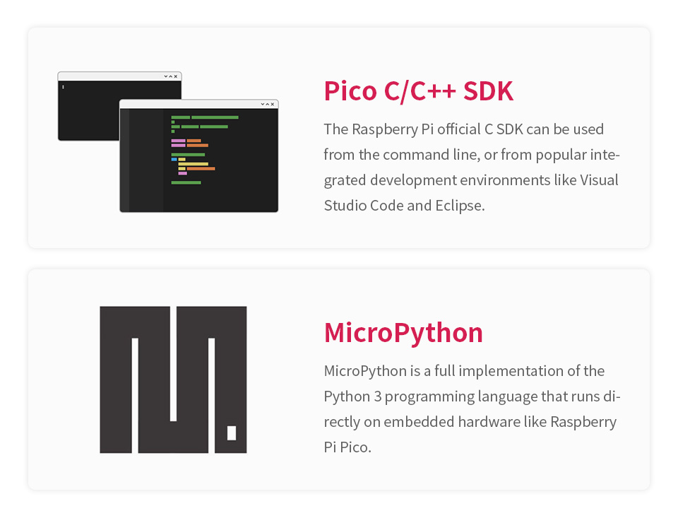
RP2040-LCD-0.96 is a low-cost, high-performance Pico-like MCU board with flexible digital interfaces. It incorporates Raspberry Pi's RP2040 microcontroller chip, as same as the one on Raspberry Pi Pico. For software development, either Raspberry Pi's C/C SDK, or the MicroPython is available, which makes it easy for you to get started, and integrate it into end products quickly.
In additional, there'rs also onboard 0.96inch IPS display, Lithium battery recharge/discharge header, and high efficiency DC-DC buck-boost chip.
Key features
- RP2040 microcontroller chip designed by Raspberry Pi in the United Kingdom
- Dual-core Arm Cortex M0 processor, flexible clock running up to 133 MHz
- 264KB of SRAM, and 2MB of on-board Flash memory
- USB-C connector, keeps it up to date, easier to use
- 0.96inch 160×80 pixels 65K colorful IPS LCD display
- Lithium battery recharge/discharge header, suitable for mobile devices
- Onboard DC-DC chip TPS63000, high efficiency DC-DC buck-boost chip, 1.8A current switch
- Castellated module allows soldering direct to carrier boards (there should be dedicated cut-out for embedding the bottom components)
- USB 1.1 with device and host support
- Low-power sleep and dormant modes
- Drag-and-drop programming using mass storage over USB
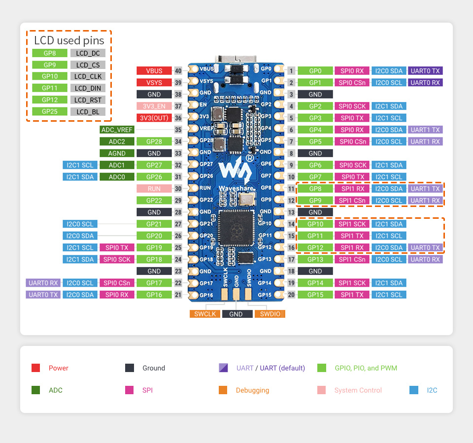
- 26 × multi-function GPIO pins
- 2 × SPI, 2 × I2C, 2 × UART, 3 × 12-bit ADC, 16 × controllable PWM channels
- Accurate clock and timer on-chip
- Temperature sensor
- Accelerated floating-point libraries on-chip
- 8 × Programmable I/O (PIO) state machines for custom peripheral support
C/C ,MicroPython support
Comprehensive SDK, dev resources, tutorials to help you easily get started
Pico-like lcd code found at :
sudo apt-get install p7zip-full
cd ~
sudo wget https://www.waveshare.com/w/upload/7/74/Pico_LCD_code.7z
7z x Pico_LCD_code.7z -o./Pico_LCD_code
cd ~/Pico_LCD_code
cd c/build/
26 × multi-function GPIO pins
configurable pin function, allows flexible development and integration
What's On Board
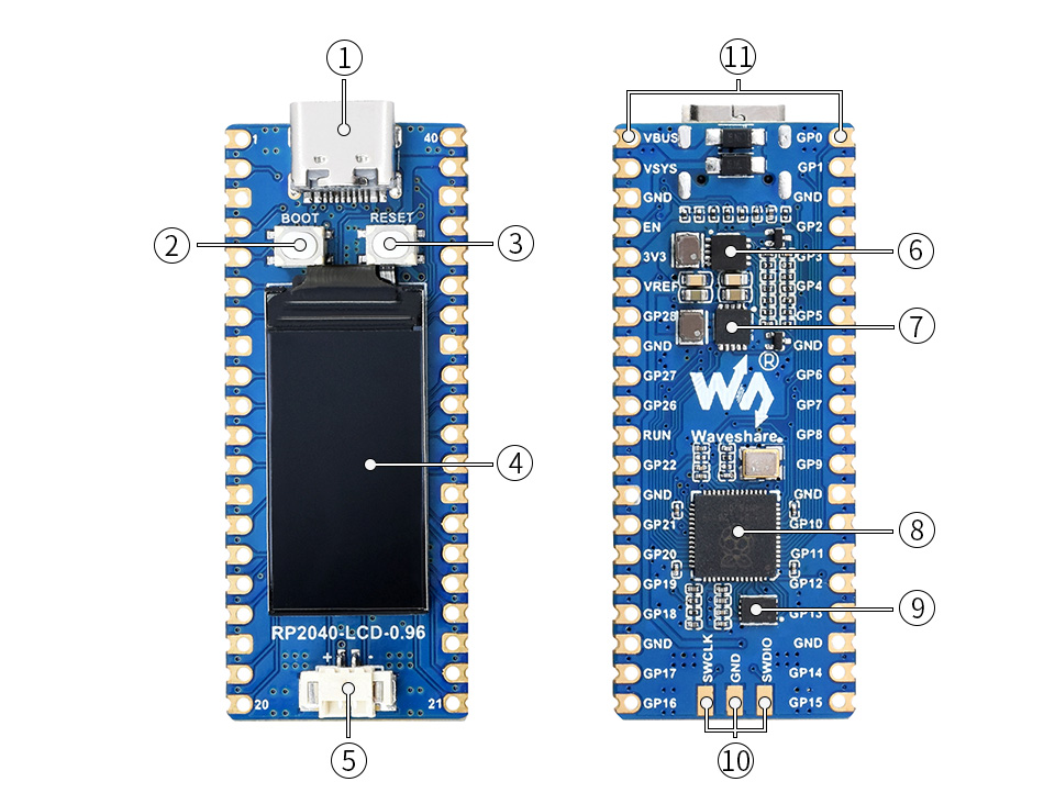
- USB Type-C connector
- BOOT button press it when resetting to enter download mode
- RESET button
- 0.96inch IPS LCD display 160 × 80 pixels, 65K colorful
- Battery header MX1.25 header, for 3.7V Lithium battery, allows recharging the battery and powering the board at the same time
- TPS63000 high efficiency DC-DC buck-boost chip
- ETA6096 high efficiency Lithium battery recharge manager
- RP2040 dual-core processor, up to 133MHz operating frequency
- W25Q16JVUXIQ 2MB NOR-Flash
- DEBUG points
- Pinout

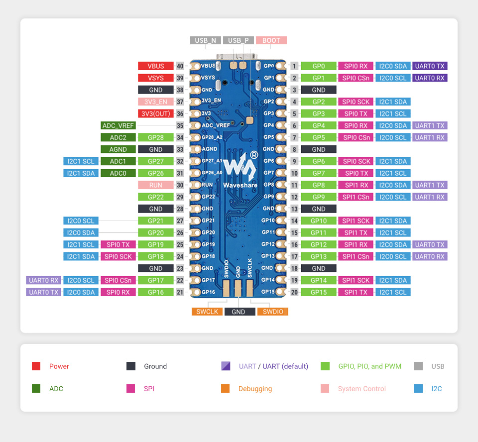
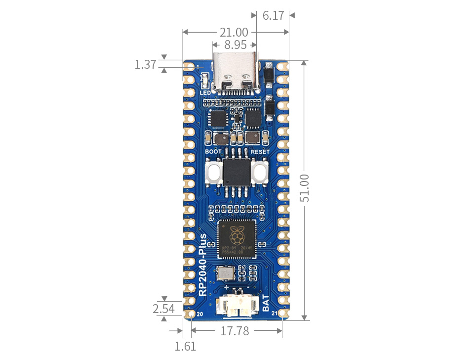
Board specifications
Need more Flash for Raspberry Pi Pico? Dislike the outdated Micro USB connector? All these problems are solved by our RP2040-Plus now.
Same as Raspberry Pi Pico, it incorporates the RP2040 microcontroller, with dual-core Arm Cortex M0+ processor running up to 133 MHz, and 26x multi-function GPIO pins.
What's different, it features onboard 4MB Flash, USB-C connector, recharge header, and higher current DC-DC chip.
Key features include
- RP2040 microcontroller chip designed by Raspberry Pi in the United Kingdom
- Dual-core Arm Cortex M0+ processor, flexible clock running up to 133 MHz
- 264KB of SRAM, and 4MB of on-board Flash memory
- USB-C connector, keeps it up to date, easier to use
- Lithium battery recharge/discharge header, suitable for mobile devices
- Onboard DC-DC chip TPS63000, high efficiency DC-DC buck-boost chip, 1.8A current switch
- Castellated module allows soldering direct to carrier boards
- USB 1.1 with device and host support
- Low-power sleep and dormant modes
- Drag-and-drop programming using mass storage over USB
- 26 × multi-function GPIO pins
- 2 × SPI, 2 × I2C, 2 × UART, 3 × 12-bit ADC, 16 × controllable PWM channels
- Accurate clock and timer on-chip
- Temperature sensor
- Accelerated floating-point libraries on-chip
- 8 × Programmable I/O (PIO) state machines for custom peripheral support
Comprehensive SDK, dev resources, tutorials to help you easily get started
26 × multi-function GPIO pins
configurable pin function, allows flexible development and integration
What's On Board?
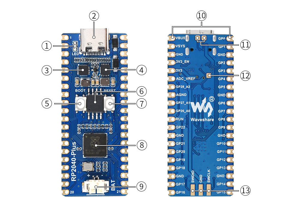
- LED user LED (not power indicator)
- ETA6096 high efficiency Lithium battery recharge manager
- TPS63000 high efficiency DC-DC buck-boost chip
- USB Type-C connector
- BOOT button press it when resetting to enter download mode
- W25Q32JVSSIQ 4MB NOR-Flash
- RESET button
- RP2040 dual-core processor, up to 133MHz operating frequency
- Battery header MX1.25 header, for 3.7V Lithium battery, allows recharging the battery and powering the board at the same time
- Pinout compatible with Raspberry Pi Pico
- USB test points connecting to USB interface
- BOOT test point connecting to BOOT button
- DEBUG points

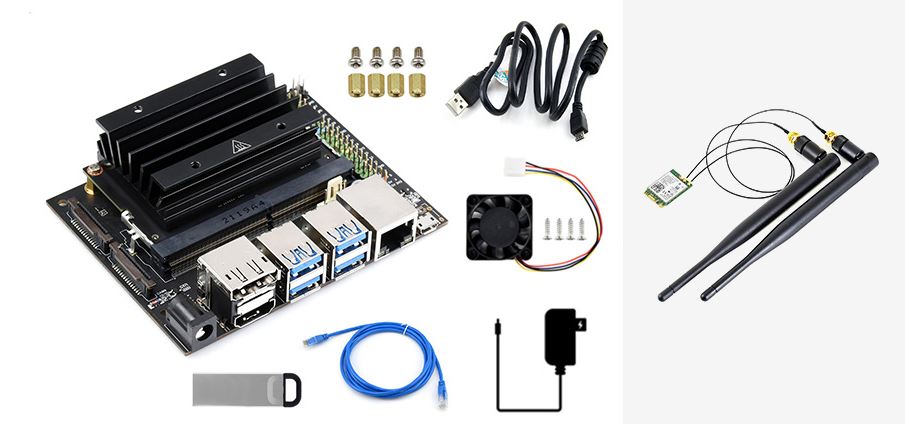
NVIDIA Jetson Nano Developer Kit is a small, powerful computer that lets you run multiple neural networks in parallel for applications like image classification, object detection, segmentation, and speech processing. All in an easy-to-use platform that runs in as little as 5 watts.
Jetson Nano delivers 472 GFLOPS for running modern AI algorithms fast, with a quad-core 64-bit ARM CPU, a 128-core integrated NVIDIA GPU, as well as 4GB LPDDR4 memory. It runs multiple neural networks in parallel and processes several high-resolution sensors simultaneously.
Jetson Nano is also supported by NVIDIA JetPack, which includes a board support package (BSP), CUDA, cuDNN, and TensorRT software libraries for deep learning, computer vision, GPU computing, multimedia processing, and much more. The SDK also includes the ability to natively install popular open source Machine Learning (ML) frameworks such as TensorFlow, PyTorch, Caffe / Caffe2, Keras, and MXNet, enables the developers to integrate their favorite AI model / AI framework into products fast and easily.
Upgraded 2-lanes CSI, instead of the previous 1-lane, easily play around with binocular vision
Introduction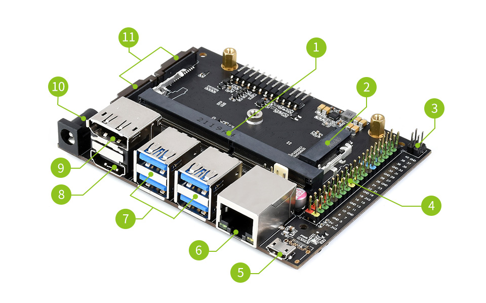
- Core module socket
- M.2 Key E connector
- PoE pins: PoE module is not included
- 40PIN GPIO header
- Micro USB port: for 5V power input or for USB data transmission
- Gigabit Ethernet port: 10/100/1000Base-T auto-negotiation, supports PoE if external PoE module is connected
- 4x USB 3.0 port
- HDMI output port
- DisplayPort connector
- DC jack: for 5V power input
- 2x MIPI CSI camera connector
| GPU | 128-core Maxwell |
|---|---|
| CPU | Quad-core ARM A57 @ 1.43 GHz |
| Memory | 4 GB 64-bit LPDDR4 25.6 GB/s |
| Storage | 16GB eMMC |
| Video Encoder | 4K @ 30 | 4x 1080p @ 30 | 9x 720p @ 30 (H.264/H.265) |
| Video Decoder | 4K @ 60 | 2x 4K @ 30 | 8x 1080p @ 30 | 18x 720p @ 30 (H.264/H.265) |
| Camera | 2x MIPI CSI-2 DPHY lanes |
| Connectivity | Gigabit Ethernet, M.2 Key E expansion connector |
| Display | HDMI and DP |
| USB | 4x USB 3.0, USB 2.0 Micro-B |
| Extension Interfaces | GPIO, I2C, I2S, SPI, UART |
What's in the box?
1 x AC8265 dual-mode NIC
1 x 32GB USB drive
1 x Cooling fan
1 x USB cable (~1.2m)
1 x Ethernet cable (~1.5m)
1 x EU 5V 4A power adapter
Resources
Wiki: JETSON-NANO-DEV-KIT
Nvidia help docs
Introduction to Jetson Developer Kits And Modules

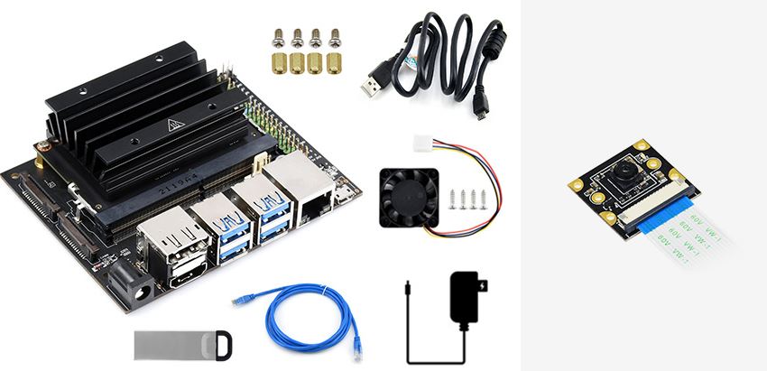
NVIDIA Jetson Nano Developer Kit is a small, powerful computer that lets you run multiple neural networks in parallel for applications like image classification, object detection, segmentation, and speech processing. All in an easy-to-use platform that runs in as little as 5 watts.
Jetson Nano delivers 472 GFLOPS for running modern AI algorithms fast, with a quad-core 64-bit ARM CPU, a 128-core integrated NVIDIA GPU, as well as 4GB LPDDR4 memory. It runs multiple neural networks in parallel and processes several high-resolution sensors simultaneously.
Jetson Nano is also supported by NVIDIA JetPack, which includes a board support package (BSP), CUDA, cuDNN, and TensorRT software libraries for deep learning, computer vision, GPU computing, multimedia processing, and much more. The SDK also includes the ability to natively install popular open source Machine Learning (ML) frameworks such as TensorFlow, PyTorch, Caffe / Caffe2, Keras, and MXNet, enables the developers to integrate their favorite AI model / AI framework into products fast and easily.
Upgraded 2-lanes CSI, instead of the previous 1-lane, easily play around with binocular vision
Introduction
- Core module socket
- M.2 Key E connector
- PoE pins: PoE module is not included
- 40PIN GPIO header
- Micro USB port: for 5V power input or for USB data transmission
- Gigabit Ethernet port: 10/100/1000Base-T auto-negotiation, supports PoE if external PoE module is connected
- 4x USB 3.0 port
- HDMI output port
- DisplayPort connector
- DC jack: for 5V power input
- 2x MIPI CSI camera connector
| GPU | 128-core Maxwell |
|---|---|
| CPU | Quad-core ARM A57 @ 1.43 GHz |
| Memory | 4 GB 64-bit LPDDR4 25.6 GB/s |
| Storage | 16GB eMMC |
| Video Encoder | 4K @ 30 | 4x 1080p @ 30 | 9x 720p @ 30 (H.264/H.265) |
| Video Decoder | 4K @ 60 | 2x 4K @ 30 | 8x 1080p @ 30 | 18x 720p @ 30 (H.264/H.265) |
| Camera | 2x MIPI CSI-2 DPHY lanes |
| Connectivity | Gigabit Ethernet, M.2 Key E expansion connector |
| Display | HDMI and DP |
| USB | 4x USB 3.0, USB 2.0 Micro-B |
| Extension Interfaces | GPIO, I2C, I2S, SPI, UART |
What's in the box?
1 x IMX219-77 Camera
1 x 32GB USB drive
1 x Cooling fan
1 x USB cable (~1.2m)
1 x Ethernet cable (~1.5m)
1 x 5V 4A power adapter
Resources
Wiki: JETSON-NANO-DEV-KIT
Nvidia help docs
Introduction to Jetson Developer Kits And Modules

NVIDIA Jetson Nano Developer Kit is a small, powerful computer that lets you run multiple neural networks in parallel for applications like image classification, object detection, segmentation, and speech processing. All in an easy-to-use platform that runs in as little as 5 watts.
Jetson Nano delivers 472 GFLOPS for running modern AI algorithms fast, with a quad-core 64-bit ARM CPU, a 128-core integrated NVIDIA GPU, as well as 4GB LPDDR4 memory. It runs multiple neural networks in parallel and processes several high-resolution sensors simultaneously.
Jetson Nano is also supported by NVIDIA JetPack, which includes a board support package (BSP), CUDA, cuDNN, and TensorRT software libraries for deep learning, computer vision, GPU computing, multimedia processing, and much more. The SDK also includes the ability to natively install popular open source Machine Learning (ML) frameworks such as TensorFlow, PyTorch, Caffe / Caffe2, Keras, and MXNet, enables the developers to integrate their favorite AI model / AI framework into products fast and easily.
Upgraded 2-lanes CSI, instead of the previous 1-lane, easily play around with binocular vision
Introduction
- Core module socket
- M.2 Key E connector
- PoE pins: PoE module is not included
- 40PIN GPIO header
- Micro USB port: for 5V power input or for USB data transmission
- Gigabit Ethernet port: 10/100/1000Base-T auto-negotiation, supports PoE if external PoE module is connected
- 4x USB 3.0 port
- HDMI output port
- DisplayPort connector
- DC jack: for 5V power input
- 2x MIPI CSI camera connector
Specifications
- GPU: 128-core Maxwell
- CPU: Quad-core ARM A57 @ 1.43 GHz
- Memory: 4 GB 64-bit LPDDR4 25.6 GB/s
- Storage: 16GB eMMC
- Video Encoder: 4K @ 30 | 4x 1080p @ 30 | 9x 720p @ 30 (H.264/H.265)
- Video Decoder: 4K @ 60 | 2x 4K @ 30 | 8x 1080p @ 30 | 18x 720p @ 30 (H.264/H.265)
- Camera: 2x MIPI CSI-2 DPHY lanes
- Connectivity: Gigabit Ethernet, M.2 Key E expansion connector
- Display: HDMI and DP
- USB: 4x USB 3.0, USB 2.0 Micro-B
- Extension Interfaces: GPIO, I2C, I2S, SPI, UART
What's in the box?
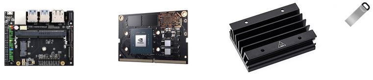
- JETSON-IO-BASE-A (carrier board)
- Jetson Nano module
- Official heatsink
- 32GB USB drive
Resources
Wiki: JETSON-NANO-DEV-KIT
Nvidia help docs
Introduction to Jetson Developer Kits And Modules

It's easy to set up, features a great resolution, comes complete with a black acrylic stand, and has touch by default!
Recent upgrades
If you were used to seeing the Self Test at power on, this has now been removed. However if you remove the jumper located on the controller board you can re-enable this feature.
This device uses the Pi's HDMI output for display, and the Pi's USB port for touch control. Assembly of the Waveshare 10.1" screen is easy, just follow this simple guide here.
Please Note. This device does require some simple set up. You will need attach the EU fitting to the power adapter.
The LCD Screen Features
- 10.1inch HDMI LCD (B)
- 1280x800 Resolution
- UK 5V 2A Power Supply Included
- Capacitive touch control
- Supports Raspberry Pi, Ubuntu, Windows 10 IoT driver free
- Can also be used as a computer monitor, supports Windows 10/8.1/8/7/XP etc.
- Supports BB Black, comes with Angstrom image
- HDMI interface for displaying, USB interface for touch control
- Input interfaces: HDMI
- Multi languages OSD menu, for power management, brightness/contrast adjustment, etc.
- Firmware is upgradable to support more new features (continually updated)
The Case Features
- Material : High quality black and clear Acrylic
- Comes with bottom holder, 45° tilt angle
- Features mounting holes for Raspberry Pi 3B/2B/B /A /B, and BB Black
What's in the box?
1 x HDMI 10.1" Touch Screen
1 x Acrylic panels
1 x HDMI cable
Resources
User Manual
Quick Assembly Guide
Wiki

Features
- Raspberry Pi Camera, supports all revisions of the Pi
- Embedded removable IR-CUT filter, eliminating color distortion in the daylight
- Comes with infrared LED, supports night vision
- 5 megapixel OV5647 sensor
- Adjustable focus distance
- Camera specifications
- CCD size : 1/4inch
- Aperture (F) : 1.8
- Focal Length : 3.6mm
- Angle of View (diagonal) : 75.7 degree
- Sensor best resolution : 1080p
- 4 screw holes
- Used for attachment
- Provides 3.3V power output
- Supports connecting infrared LED and/or fill flash LED
- Dimension: 31mm × 32mm
Note: to use the camera with Raspberry Pi Zero / Zero W / Zero WH, you need to buy a specific cable: Raspberry Pi Zero v1.3 Camera Cable
The new Raspberry Pi OS release includes the new Picamera2 Python camera interface.
What's in the box?
1 x Camera
Resources

Please note: Raspberry Pi not included
The RPi Relay Board gives your Pi the ability to control high voltage/high current devices, easily makes normal home appliances become intelligent.
RPi Relay Board Features
- High quality relays, loads up to 250VAC/5A, 30VDC/5A
- Photo coupling isolation, prevent interference from high voltage circuit
- Onboard LEDs for indicating relays status
- Relay control jumper, allows to control the relays by custom pins other than the default pins
- Comes with development resources, including examples in wiringPi, WebioPi, shell, python, and bcm2835
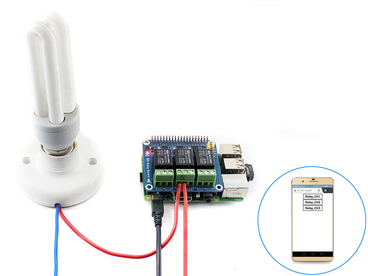
What's on the RPi Relay Board
- Raspberry Pi GPIO interface: for connecting Raspberry Pi
- Relay screw terminal: for connecting target devices
- Relays
- Photocoupler: PC817
- Relay indicator
- LED on: relay NC is opened, NO is closed
- LED off: relay NC is closed, NO is opened
- Power indicator
- Relay control jumper
- short the jumper: control the relays by default I/Os used in the example code
- open the jumper: control the relays by custom I/Os through jumper wires
What's in the box?
1 x RPi Relay Board
1 x RPi screws pack (2pcs)
Resources

Note: Raspberry Pi is NOT included. Batteries are not included
AlphaBot2-Pi (EN) can be used with Raspberry Pi4 ,you will need to buy a USB Micro-B to USB-C Adapter
This AlphaBot2 robot kit is designed to use with Raspberry Pi 3/4 Model B (not included). It features rich common robot functions including line tracking, obstacle avoiding, Bluetooth/infrared/WiFi remote control, video monitoring, etc.
Thanks to the highly integrated modular design, it is fairly easy to assemble by a snap, no soldering, no wiring. After a few minutes spent on hardware assembling, you're almost there, our open source demo codes is ready to help you get started fast.
AlphaBot2 FeaturesAlphaBot2 employs a 2-layer structure to provide excellent stability and compatibility.
AlphaBot2-Base, the lower base chassis:
- 5-ch infrared sensor, analog output, combined with PID algorithm, stable line tracking
- Onboard modules like line tracking, obstacle avoiding, needs no messy wiring
- TB6612FNG dual H-bridge motor driver, compared with L298P, it's more efficient, more compact, and less heating
- N20 micro gear motor, with metal gears, low noise, high accuracy
- Onboard RGB LEDs, true color lighting, pretty cool
AlphaBot2-Pi, the upper adapter board for controller:
- LM2596 voltage regulator, provides the Pi with stable 5V power
- TLC1543 AD acquisition chip, allows the Pi to use analog sensors
- PCA9685 servo controller, make it more smoothly to rotate the pan head
- CP2102 UART converter, easy for controlling the Pi via UART
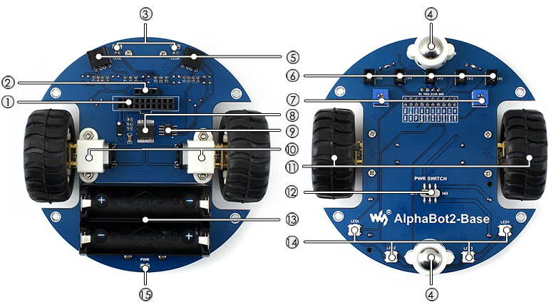
- AlphaBot2 control interface: for connecting sorts of controller adapter board
- Ultrasonic module interface
- Obstacle avoiding indicators
- Omni-direction wheel
- ST188: reflective infrared photoelectric sensor, for obstacle avoiding
- ITR20001/T: reflective infrared photoelectric sensor, for line tracking
- Potentiometer for adjusting obstacle avoiding range
- TB6612FNG dual H-bridge motor driver
- LM393 voltage comparator
- N20 micro gear motor reduction rate 1:30, 6V/600RPM
- Rubber wheels diameter 42mm, width 19mm
- Power switch
- Battery holder: supports 14500 batteries
- WS2812B: true color RGB LEDs
- Power indicator
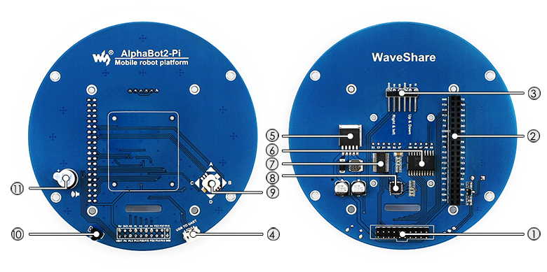
- AlphaBot2 control interface: for connecting AlphaBot2-Base
- Raspberry Pi interface: for connecting Raspberry Pi 3 Model B
- Servo interface
- USB TO UART: easy for controlling the Pi via UART
- LM2596: 5V voltage regulator
- TLC1543: 10-bit AD acquisition chip, allows the Pi to use analog sensors
- PCA9685: servo controller, make it more smoothly to rotate the pan head
- CP2102: USB TO UART converter
- Joystick
- IR receiver
- Buzzer
Examples
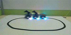
AlphaBot2 multi robots line following
 AlphaBot2-Pi robot obstacle avoiding
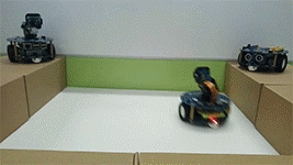 AlphaBot2-Pi robot RGB LED remote control
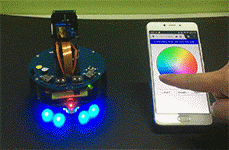 AlphaBot2-Pi robot video monitor
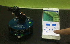 AlphaBot2-Pi robot Bluetooth control
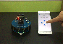
What's in the box?
Note: this product requires two 14500 batteries to work, which are NOT included and should be purchased separately. Even though the battery holder fits the normal AA batteries DO NOT USE THEM! A 14500 lithium cell is identical in shape and size to a standard AA battery. But that is where the similarities end. AA supplies 1.5V each where 14500 supply 3.7V each.
1 x AlphaBot2-Base (base chassis)
1 x RPi Camera (B)
1 x Micro SD Card 16GB
1 x Power adapter US standard 5V/2.5A USB output
2 x SG90 servo
1 x 2 DOF pan and tilt kit
1 x IR remote controller
1 x FC-20P cable 8cm
1 x USB type A plug to micro B plug cable
1 x 15PIN FFC 25cm
1 x AlphaBot2-Pi screws
1 x Micro SD Card Reader
1 x Screwdriver
Resources
Wiki : www.waveshare.com/wiki/AlphaBot2-Pi

Features
- Raspberry Pi Night Vision Camera, supports all revisions of the Pi
- 5 megapixel OV5647 sensor
- Camera specifications
- CCD size : 1/4inch
- Aperture (F) : 2.9
- Focal Length : 3.29MM
- Diagonal : 72.4 degree
- Sensor best resolution : 1080p
- 4 screw holes
- Used for attachment
- Provides 3.3V power output
- Supports connecting infrared LED and/or fill flash LED
- Dimension : 25mm x 24mm x 6mm
Note: to use the camera with Raspberry Zero, you need to buy a specific cable: Raspberry Pi Zero Camera Cable
Raspberry Pi 2/3 ribbon cable included
Getting started with PiCamera
Development resources:user manual, etc.
Download: www.waveshare.com/wiki/RPi_Camera_(E)
This is a handy, low power Raspberry Pi HAT which features multi communication functionalities: GSM, GPRS, GNSS and Bluetooth.
It allows your Pi to easily make a telephone call, send messages, connect to wireless Internet, global position, transfer data via Bluetooth, and so on.
General
- Raspberry Pi connectivity, compatible with Raspberry Pi 2B/3B/4B/Zero/Zero W/Zero WH/Zero 2W
- Supports SMS, phone call, GPRS, DTMF, HTTP, FTP, MMS, email, etc.
- Support GPS, COMPASS, Glonass, LBS base station positioning, omni-positioning
- Bluetooth 3.0, supports data transferring through Bluetooth
- Onboard USB TO UART converter CP2102 for UART debugging
- 6x LEDs for indicating the module working status
- SIM card slot for 1.8V/3V SIM card
- RTC with backup battery holder
- Baudrate auto detection (1200bps ~115200bps)
- Control via AT commands (3GPP TS 27.007, 27.005, and SIMCOM enhanced AT Commands)
- Supports SIM application toolkit: GSM 11.14 Release 99
- Comes with development resources and manual (examples for Raspberry Pi/Arduino/STM32)
GSM/GPRS
- Band
- GSM 850/EGSM 900/DCS 1800/PCS 1900 MHz
- Quad-band auto search
- Compliant to GSM phase 2/2
- Emitting power
- Class 4 (2W @ GSM 850/EGSM 900 MHz)
- Class 1 (1W @ DCS 1800/PCS 1900 MHz)
- GPRS connectivity
- GPRS multi-slot class 12 (default)
- GPRS multi-slot class 1~12 (configurable)
- GPRS data feature
- Downlink speed: max 85.6kbps
- Uplink speed: max 85.6kbps
- Coding schemes: CS-1\CS-2\CS-3\CS-4
- Supports PAP (Password Authentication Protocol) for PPP connection
- Supports PBCCH
- Supports USSD
- SMS
- Supports: MT/MO/CB/Text/PDU mode
- SMS storage: SIM card
- Audio
- Voice encode/decode mode: Half Rate\Full Rate\Enhanced Full Rate\Adaptive muti rate
- Supports echo cancellation
- Supports noise reduction
GNSS
- Receiver type
- 33 tracking channels
- 99 acquisition channels
- GPS L1 C/A code
- Sensitivity
- Tracking: -165 dBm
- Cold starts : -148 dBm
- Time-To-First-Fix
- Cold starts : 28s (typ.)
- Hot starts : < 1s
- Warm starts: 26s
- Accuracy
- Horizontal position : <2.5m CEP
Bluetooth
- Integrates AT commands
- Compliant to Bluetooth specification3.0 EDR
- Supports SPP, OPP, HFP/HSP, etc.
Misc
- Operating voltage: 5V
- Operating temperature: -40°C ~ 85°C
- Storage temperature: -45°C ~ 90°C
- Dimensions: 30.2mm x 65mm
What's on Board
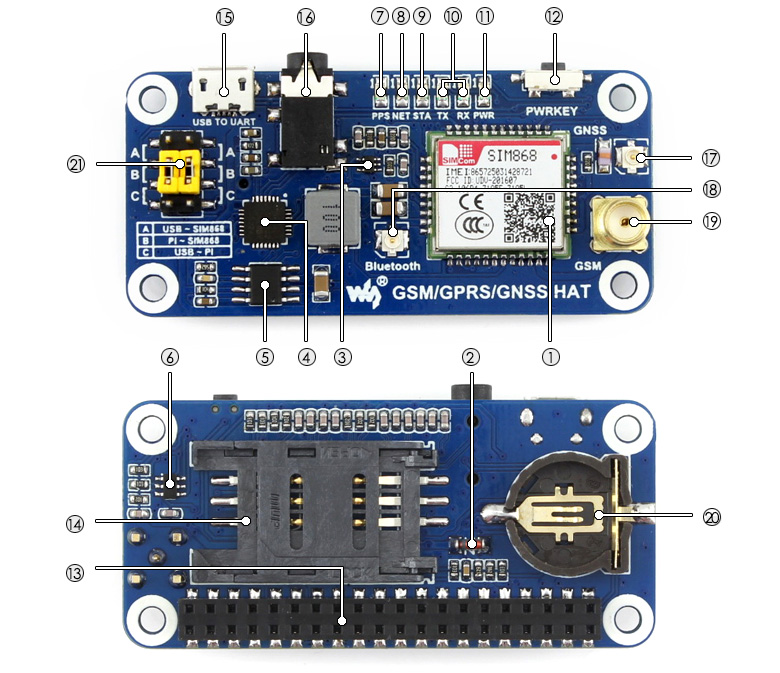
- SIM868 module
- ZMM5V1: regulator diode
- SMF05C: TVS diode
- CP2102: USB TO UART converter
- MP1482: power chip
- NDC7002N: voltage level translator
- GPS status indicator
- NET indicator:
- flashes fast when the module starts up
- flashes slowly after GSM register succeed
- STA module working status indicator
- SIM868 UART Tx/Rx indicator
- Power indicator
- SIM868 control button: press the button and hold for 1s, to startup/shutdown the SIM868
- Raspberry Pi GPIO connector
- SIM card slot
- USB TO UART interface
- 3.5mm earphone/mic jack
- GNSS antenna connector
- Bluetooth antenna connector
- GSM antenna connector
- CR1220 battery holder: for RTC backup battery
- UART selection switch
- A: control the SIM868 through USB TO UART
- B: control the SIM868 through Raspberry Pi
- C: access Raspberry Pi through USB TO UART
What's in the box?
1 x GSM/GPRS/GNSS/Bluetooth HAT
1 x GSM Antenna
Resources

The Pioneer600 is a blue expansion board that clicks onto the GPIO pins of Raspberry Pi and adds a range of additional features.
First of these features we noticed was a five-way joystick and 0.96-inch OLED display. This is backed up by a dual-LED and buzzer. On closer inspection, we discovered the on-board LFN0038K to enable remote control. A DS3231 real-time clock is also included (you’ll need to supply your own CR1220 button battery).
There is a built-in BMP280 for measuring air pressure and temperature, but it’s the available ports for external sensors that are the key attraction: a PCF8591, 8-bit resolution, screw terminal interface, a 1-Wire device (a DS18B20 thermometer is included), a 4×4 pin sensor interface, and GPIO expansion.
There is also a micro USB to UART connection and cable supplied. UART is normally used to debug Raspberry Pi, but with debugging mode disabled, you can send data to and from Raspberry Pi and a connected PC.
Pioneer600 Features
- Supports Raspberry Pi A /B /2B/3B/3B
- <Standard I/O> dual LED, joystick, buzzer, the basic components
- <USB TO UART> CP2102, control the Pi through serial terminal
- <Display> 0.96inch OLED, big world in the little screen
- <RTC> DS3231, high precision, backup battery holder is also available
- <AD/DA> PCF8591, 8-bit resolution, screw terminal IO interface
- <GPIO Expansion> PCF8574, more GPIO, more possibility
- <IR Control> LFN0038K, Raspberry Pi remote control comes true
- <Pressure Sensor> BMP280, measuring air pressure and temperature
- <1-WIRE> for connecting 1-WIRE devices, DS18B20 is included
- <Sensor Interface> for connecting various sensors
What's on the Pioneer600
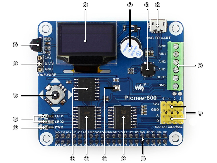
- Raspberry Pi GPIO interface : for connecting Raspberry Pi
- USB TO UART : control the Pi through serial terminal
- AD/DA IO interface : screw terminal
- 1-WIRE interface : for connecting 1-WIRE devices like DS18B20
- Sensor interface : for connecting various sensors
- 0.96inch OLED : SSD1306 driver, 128×64 resolution, SPI interface
- Buzzer
- CP2102 : USB TO UART converter
- PCF8591 : 8-bit AD/DA converter, I2C interface
- BMP280 : pressure sensor, I2C interface
- PCF8574 : I/O expansion chip, I2C interface
- DS3231 : high precision RTC chip, I2C interface
- Power indicator
- User LED
- Joystick
- LFN0038K IR receiver
Examples
| Peripheral | Interface | Python | WiringPi | BCM2835 C Library | SysFs |
|---|---|---|---|---|---|
| LED | I/O | √ | √ | √ | √ |
| KEY | I/O | √ | √ | √ | |
| IRM | I/O | √ | √ | √ | |
| UART | UART | √ | √ | ||
| DS18B20 | ONE-WIRE | √ | √ | ||
| PCF8574 | I2C | √ | √ | √ | √ |
| PCF8591 | I2C | √ | √ | √ | |
| DS3231 | I2C | √ | √ | √ | |
| BMP280 | I2C | √ | √ | √ | |
| OLED | SPI | √ | √ | √ |
Development Resources
- User manual
- Schematic
- Demo codes : python and C (WringPi/BCM2835 C Library/SysFs)
- Raspberry Pi tutorials
- Raspbian (configured system image)
What's in the box?
1 x Pioneer600 board
Resources

- 1024×600 high resolution
- Resistive touch control
- Compatible and Direct-connect with any revision of Raspberry Pi (except the Pi 1 model B or Pi Zero, which requires an HDMI cable)
- Drivers provided (works with your own Raspbian/Ubuntu directly)
- Also works as a computer monitor, in this case, touch panel is unavailable and HDMI cable is required
- HDMI interface for displaying, no I/Os required (however, the touch panel still needs I/Os)
- Backlight can be turned off to lower power consumption
Interface
| PIN NO. | SYMBOL | DESCRIPTION |
|---|---|---|
| 1, 17 | 3.3V | Power positive (3.3V power input) |
| 2, 4 | 5V | Power positive (5V power input) |
| 3, 5, 7, 8, 10, 11, 12, 13, 15, 16, 18, 24 | NC | NC |
| 6, 9, 14, 20, 25 | GND | Ground |
| 19 | TP_SI | SPI data input of Touch Panel |
| 21 | TP_SO | SPI data output of Touch Panel |
| 22 | TP_IRQ | Touch Panel interrupt, low level while the Touch Panel detects touching |
| 23 | TP_SCK | SPI clock of Touch Panel |
| 26 | TP_CS | Touch Panel chip selection, low active |
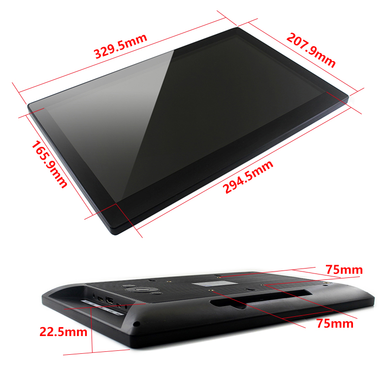
External Dimensions
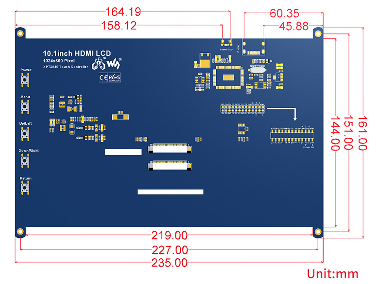
What's in the box?
1 x 10.1inch Resistive Touch Screen
Resources

Features
- 13.3inch IPS screen,1920x1080 high resolution
- Toughened glass capacitive touch panel, 6H hardness
- Supports popular mini PCs such as Raspberry Pi, BB Black, as well as general desktop computers
- When works with Raspberry Pi, supports Raspbian, Ubuntu, WIN10 IOT, single touch, and driver free
- When work as a computer monitor, supports Windows 10/8.1/8/7, ten-points touch, and driver free
- Multi languages OSD menu, for power management, brightness/contrast adjustment, etc.
- 3.5mm audio jack, supports HDMI audio output
- Embedded ferrite Hi-Fi speaker
- Also supports VGA input (specific cable is required and should be purchased separately)
- 75x75mm spacing mounting holes (M4 screw hole) for general wall mount
- Comes with 75° tilt angle stand
External Dimension
What's in the box?
1 x 13.3inch Capacitive Touch HDMI LCD
Resources
Wiki : www.waveshare.com/wiki/13.3inch_HDMI_LCD_(H)_(with_case)

The Li-ion Battery HAT integrates SW6106 power bank management chip, allows providing 5V regulated power supply to your Pi from a 14500 battery, turns the Pi into a portable device. It will charge the battery as well, supports bi-directional quick charge. This module can be used as a universal mini power bank, also works with other 5V devices.
- Onboard SW6106 chip, supports bi-directional quick charge, supports multi quick charge protocols like PD/QC/FCP/PE/SFCP
- Lithium battery protection circuitry, provides reverse protection, over charge/discharge protection, over current protection, and short circuit protection
- Onboard indicators: quick charge, warning, and power capacity
Specifications
- Output voltage: 5V
- Applicable battery: 3.7V 14500 lithium battery (4.2V when full charged)
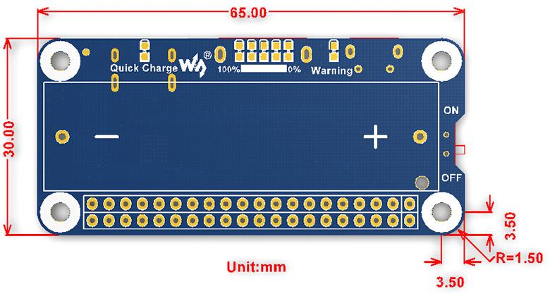
- Dimension: 65mm × 30mm
- Mounting hole size: 3.0mm
What's on Board
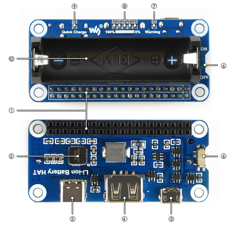
- Raspberry Pi GPIO connector: for connecting Raspberry Pi
- SW6106 power management chip
- USB Type-C connector: battery charge/power output
- USB Type-A connector:power output
- Micro USB connector:battery charge
- Raspberry Pi power switch
- Battery warning indicator: on when the battery is reverse
- Battery power capacity indicator: 5x LEDs to indicate the power capacity and charging status
- Quick charge indicator: on when quick charging
- 14500 battery holder
Dimensions
What's in the box?
1 x Li-ion Battery HAT
Resources

Overview
The RPi Relay Board (B) is an expansion board with 8-ch relays for Raspberry Pi. It gives your Pi the ability to control high voltage products such as home appliances.
- Supports Raspberry Pi A /B /2B/3B/3B /4B
- High quality relays, loads up to 5A 250V AC or 5A 30V DC
- Photo coupling isolation, prevent interference from high voltage circuit
- Standard rail mount bottom case
- Onboard LEDs for indicating relays status
- Relay control pin selection jumper, allows to control the relays by custom pins other than the default pins
- Reserved control Interface, allows to work with controllers like PLC
- Comes with development resources, including examples in wiringPi, bcm2835, python, python-bottle (webpage control), and crontab (cron job)
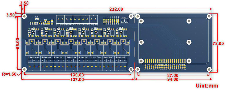
Specifications
- Power supply voltage: 5V
- Trigger signal: 3.3V/5V
- Relay channels: 8-ch
- Contact form: SPDT-NO,NC
- Closed current: 6mA (per channel)
- Connector: screw terminal block
- Dimension: 232 × 72 (mm)
- Mounting hole size: 3.0mm
Dimensions
What's in the box?
1 x RPi Relay Board (B)
1 x Rail mount bottom case
1 x Screws pack
Resources

This AlphaBot2 robot kit is designed to use with the BBC micro:bit (not included). It features rich common robot functions including line tracking, obstacle avoiding, ultrasonic ranging, Bluetooth/2.4G remote control, etc.
Thanks to the highly integrated modular design, it is fairly easy to assemble by a snap, no soldering, no wiring. After a few minutes spent on hardware assembling, you're almost there, our open source demo codes is ready to help you get started fast.
AlphaBot2 FeaturesAlphaBot2 employs a 2-layer structure to provide excellent stability and compatibility.
AlphaBot2-Base, the lower base chassis:
- 5-ch infrared sensor, analog output, combined with PID algorithm, stable line tracking
- Onboard modules like line tracking, obstacle avoiding, needs no messy wiring
- TB6612FNG dual H-bridge motor driver, compared with L298P, it's more efficient, more compact, and less heating
- N20 micro gear motor, with metal gears, low noise, high accuracy
- Onboard RGB LEDs, true color lighting, pretty cool
AlphaBot2 for micro:bit, the upper adapter board for controller:
- micro:bit dedicated connector, for easily connecting with the micro:bit
- MP1584 voltage regulator, provides stable 5V output
- RT9193-33 voltage regulator, provides stable 3.3V voltage to the micro:bit
- TLC1543 AD acquisition chip, allows the micro:bit to use analog sensors
- PCA9685 PWM control chip, I/O expander
- Onboard buzzer to play music
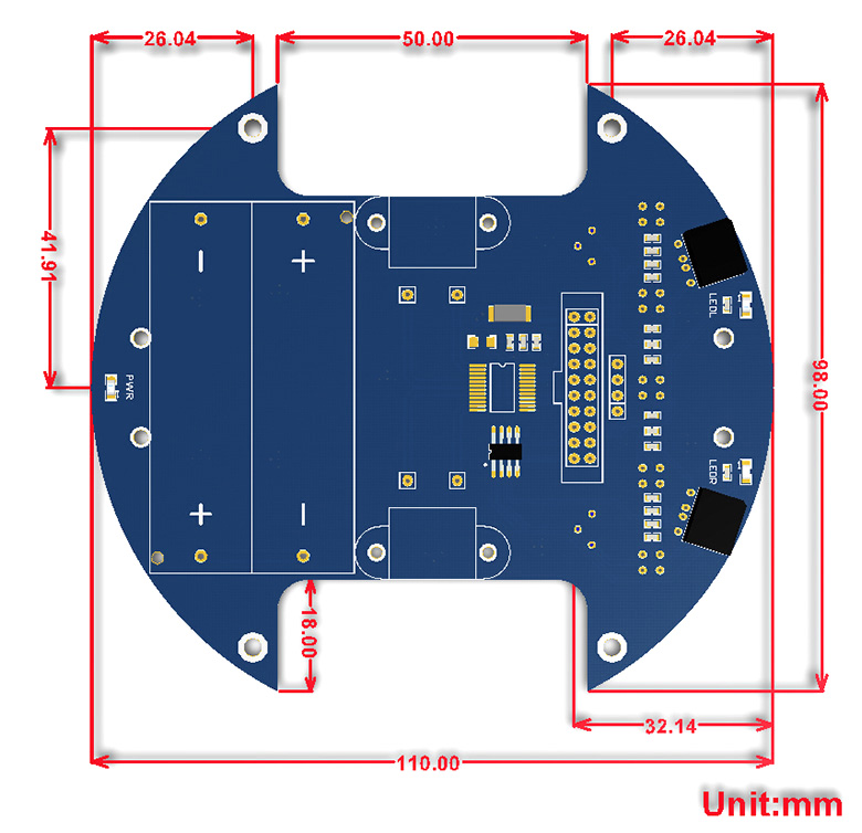
What's on the AlphaBot2-Base

- AlphaBot2 control interface: for connecting sorts of controller adapter board
- Ultrasonic module interface
- Obstacle avoiding indicators
- Omni-direction wheel
- ST188: reflective infrared photoelectric sensor, for obstacle avoiding
- ITR20001/T: reflective infrared photoelectric sensor, for line tracking
- Potentiometer for adjusting obstacle avoiding range
- TB6612FNG dual H-bridge motor driver
- LM393 voltage comparator
- N20 micro gear motor reduction rate 1:30, 6V/600RPM
- Rubber wheels diameter 42mm, width 19mm
- Power switch
- Battery holder: supports 14500 batteries
- WS2812B: true color RGB LEDs
- Power indicator
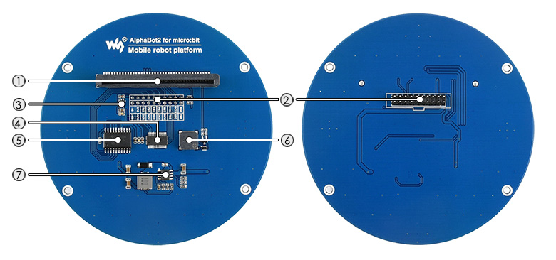
- micro:bit connector
- AlphaBot2-Base header: for connecting with the base board
- RT9193-33: 3.3V voltage regulator, stable power supply for the micro:bit
- PCA9685: PWM control chip, I/O expander, I2C interface
- TLC1543: 10-bit AD acquisition chip, allows the micro:bit to use analog line tracking sensor
- Buzzer
- MP1584 5V voltage regulator
 Development Resources
Wiki : www.waveshare.com/wiki/AlphaBot2_for_micro:bit
Note: this product requires two 14500 batteries to work, which are NOT included and should be purchased separately.
Note: the controller micro:bit is NOT included.
AlphaBot2 for micro:bit Acce Pack- AlphaBot2 for micro:bit (adapter board) x1
- AlphaBot2-Base (base chassis) x1
- Ultrasonic sensor x1
- FC-20P cable 8cm x1
- USB type A plug to micro B plug cable x1
- AlphaBot2 for micro:bit screws x1
- Screwdriver x1

This neat little 4 port USB hub pHAT for the Raspberry Pi B+/2/3 & Raspberry Pi Zero/W, provides 4 extra USB ports for your Pi and features a USB to UART converter for easy serial communication!
The board comes in a pHAT format and comes complete with micro USB cable, and Micro USB/Micro USB shim PCB. Raspberry Pi 3, Zero and dongle not included.
Features
- 4 USB Ports, compatible with USB2.0/1.1
- Onboard USB to UART, convenient for Raspberry Pi serial debugging
- Onboard multi indicators, for monitoring the status of power, USB to UART, and each USB port
- Operating voltage: 5V
- Dimension: 65mm × 30mm
- Mounting hole size: 3.0mm
Assembly Instructions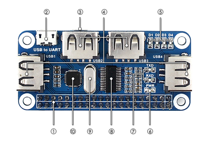
- Raspberry Pi GPIO interface: for connecting Raspberry Pi
- USB to UART: for controlling the Raspberry Pi via serial terminal
- USB HUB interface (Micro USB): for connecting the HUB to the Raspberry Pi USB port
- Raspberry Pi Zero / Zero W: connected via Micro USB to Micro USB PCB
- Raspberry Pi B+ / 2B / 3B: connected via USB to Micro USB cable
- USB extended ports: USB1~USB4
- USB port indicators: dedicated indicator for each USB port, D1~D4 for USB1~USB4 respectively
- Power indicator
- USB to UART indicator
- FE1.1S: USB HUB chip
- 12MHz crystal
- CP2102: USB to UART converter
What's in the box?
1 x USB HUB HAT
1 x Micro USB connector
1 x Micro USB cable
1 x RPi screws pack (2pcs)
Resources

This is a colorful display module designed for the BBC micro:bit, 1.8inch diagonal, 160x128 pixels, capable of displaying 65K colors.
Tired of the 5x5 LED matrix? Time to get a tiny monitor for your micro:bit, this one would be the ideal choice.
- micro:bit edge connector, directly pluggable
- Embedded driver ST7735S, supports 65K colors
- Onboard SRAM 23LC1024, used as display cache, no more out of memory
- SPI interface, takes up only a few IO pins
- Backlight adjustment via PWM
- Reserved solder pads for control interface, make it easy to connect with Arduino/Nucleo boards
- Comes with development resources (micro:bit graphical demo/user manual, etc.)
Specifications
- Driver: ST7735S
- Resolution: 160x128
- Display color: RGB, 65K colors
- Operating voltage: 3.3V
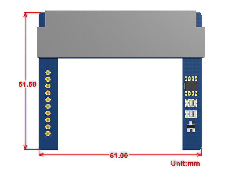
- Dimension: 61mm x 51.5mm
Pinouts
| PIN | micro:bit PIN | DESCRIPTION |
|---|---|---|
| 3V3 | 3V3 | Power |
| GND | GND | Ground |
| MISO | P14 | SPI data master input/slave output |
| MOSI | P15 | SPI data master output/slave input |
| SCK | P13 | SPI clock input |
| LCD_CS | P16 | LCD chip selection |
| RAM_CS | P2 | SRAM chip selection |
| DC | P12 | LCD data/command |
| RST | P8 | LCD reset |
| BL | P1 | LCD backlight |
Dimensions
What's in the box?
1 x 1.8inch LCD for micro:bit
Resources

- Supports any revision of Raspberry Pi (directly-pluggable)
- Provides your Pi with 16 touch keys
- Features TONTEK TonTouch touch pad detector IC TTP229-LSF, supports up to 16 keys with adjustable sensitivity and built-in LDO
- The system re-calibrates automatically when all keys are not detected touch more than about 4 seconds
- Interface : I2C
- Keys : 16
- Sampling rate : 8Hz
- Human Body Mode : 6KV
- Operating voltage : 2.4V-5.5V
- Operating temperature : -40℃ to 85℃
- Storage temperature : -50℃ to 125℃
- Dimensions : 8.5CM × 5.6CM
- After power-on have about 0.5sec stable-time. During the time do not touch the key pad, and all functions are disabled
- VCC : Power supply (2.4V-5.5V)
- GND : Ground
- SDA : I2C SDA
- SCL : I2C SCL
Downloads/Development resources:
schematic, demo code, datasheets, etc.
Download: www.waveshare.com/wiki/RPi_Touch_Keypad