
WaveShare


By utilizing the new generation LoRa spread spectrum modulation technology, the communication distance of the module is as long as 5km, also supports auto repeating to transmit longer. Other features include Wake on Radio, wireless config, carrier sensing, communication key, and so on.
Comparing with normal LoRa modules, the SX1262 LoRa HAT achieves longer communication distance, higher rate, lower consumption, better safety and anti-interference. It is suitable for various applications such as industrial control, smart home, data collection, etc.
Features
- Standard Raspberry Pi 40PIN GPIO extension header, supports Raspberry Pi series boards
- Onboard CP2102 USB TO UART converter, for serial debugging
- Brings the UART control interface, for connecting host boards like Arduino/STM32
- 4x LED indicators, easy to check the module status
- LoRa spread spectrum modulation technology, up to 81 available signal channel, longer communication distance, more robust to interference
- Auto multi-level repeating, suit for ultra long range communication, allows multi network on the same region
- Low power consumption features like deep sleeping and Wake on Radio, ideal for battery-powered applications
- Customizable communication key which won't be retrieved, greatly improves the security of user data
- Supports LBT, monitoring the signal channel noise before transmitting, greatly improves the success ratio under extreme environment
- Supports RSSI signal intensity indicating, for evaluating signal quality, tuning the network
- Supports wireless parameter configuration, by sending wireless command/data packet, remotely configure or retrieve the module parameter
- Supports fixed-point transmission, broadcast, signal channel monitor
- Comes with development resources and manual (examples for Raspberry Pi/STM32)
What's on Board?
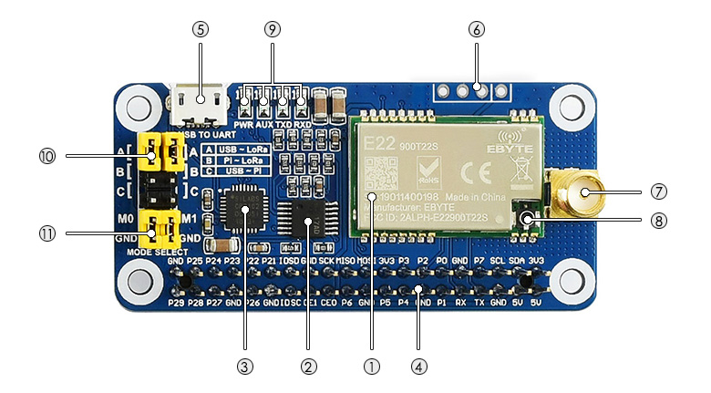
- SX1262 LoRa module
- 74HC125V: voltage level translator
- CP2102: USB TO UART converter
- Raspberry Pi GPIO connector: for connecting with Raspberry Pi
- USB TO UART port
- UART header: for connecting host boards like STM32/Arduino
- SMA antenna connector
- IPEX antenna connector
- Indicators:
- RXD/TXD: UART RX/TX indicator
- AUX: auxiliary indicator
- PWR: power indicator
- UART selection jumpers
- A: control the LoRa module through USB TO UART
- B: control the LoRa module through Raspberry Pi
- C: access Raspberry Pi through USB TO UART
- LoRa mode selection jumpers
- short M0, short M1: transmission mode
- short M0, open M1: configuration mode
- open M0, short M1: WOR mode
- open M0, open M1: deep sleep mode
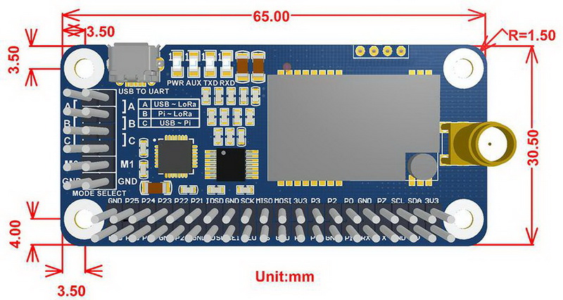
Dimensions
What's in the box ?
1 x SX1262 868M LoRa HAT
1 x USB type A plug to micro plug cable
1 x 868MHz antenna
Resources
Wiki : www.waveshare.com/wiki/SX1262_868M_LoRa_HAT

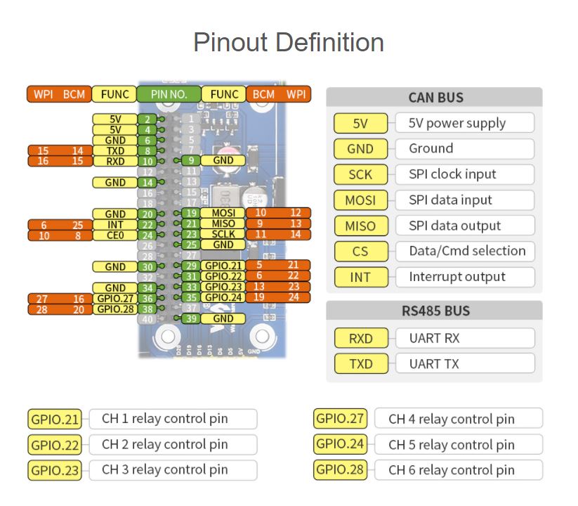
Industrial 6-ch Relay Module for Raspberry Pi Zero, RS485/CAN, Isolated Protections, Tailored For Raspberry Pi Zero Series also Suitable For Raspberry Pi Zero With Pre-Soldered Pin header.
Features
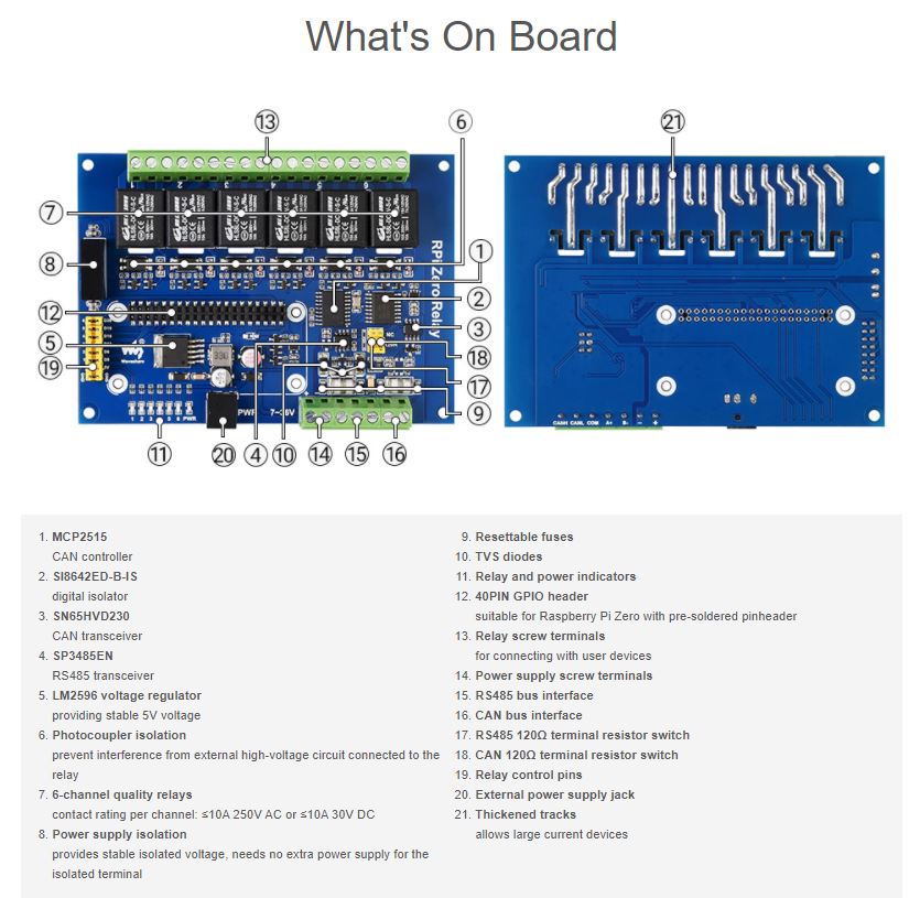
- RS485 half-duplex communication: using SP3485, UART control, auto RX/TX switch
- CAN half-duplex communication: using MCP2515 SN65HVD230 solution, SPI control
- Onboard unibody power supply isolation, provides stable isolated voltage, needs no extra power supply for the isolated terminal
- Onboard photocoupler isolation, prevent interference from external high-voltage circuit connected to the relay
- Onboard TVS (Transient Voltage Suppressor), effectively suppress surge voltage and transient spike voltage in the circuit, lightningproof & anti-electrostatic
- Onboard resettable fuses and protection diodes, ensuring current/voltage stable output, preventing over current/voltage, better shock-resistance performance
- High quality relay, contact rating: ≤10A 250V AC or ≤10A 30V DC
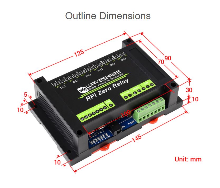
- ABS protection enclosure with rail-mount support, easy to install, safe to use
- Comes with development resources and manual (wiringPi and python examples)
Specifications
| OPERATING VOLTAGE | 7V~36V (industrial input voltage compatible) | RELAY CHANNEL | 6 ch |
|---|---|---|---|
| COMMUNICATION PROTOCOL | RS485, CAN | CONTACT FORM | 1NO 1NC |
What's in the box?
1 x ABS protection enclosure (top and bottom)
1 x RPi Zero Relay
1 x Screwdriver
1 x 12V 1A power adapter
1 x Screws pack
Resources
WIKI: RPi_Zero_Relay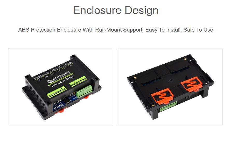


Features at a glance
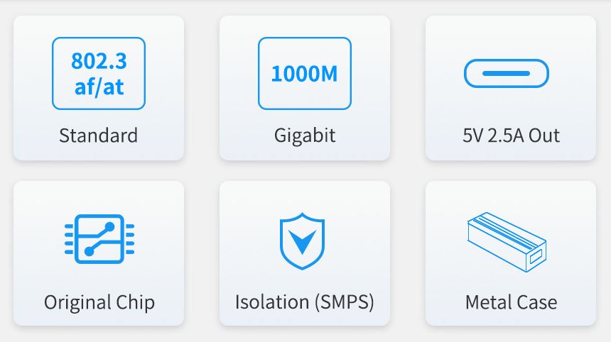
- Incorporates original chip Si3404, high-efficiency, high-safety, stable-performance
- 10/100/1000Mbps auto-negotiation Ethernet port
- 802.3af/at-compliant PoE (Power over Ethernet) standard
- Isolated SMPS (Switching Mode Power Supply), effectively protecting the powered device
- 5V DC output, suitable for powering Raspberry Pi and other small-scale network devices
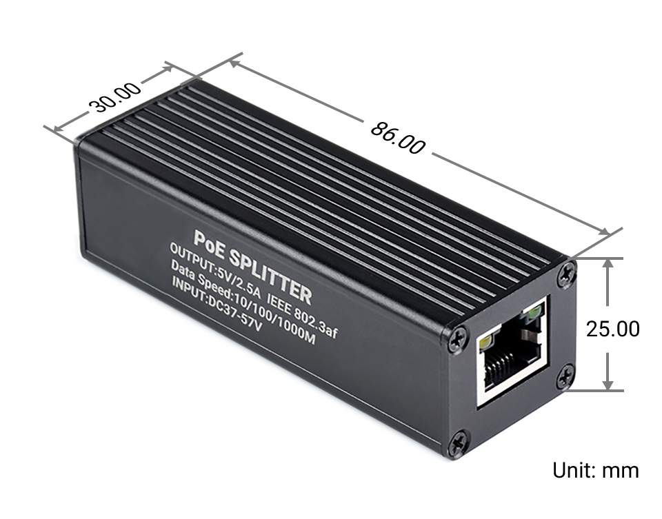
- Black dull-polish metal case, sturdy and rugged, higher protection level, better heat dissipation
Specifications
| Power supply | supports 1/2(+); 3/6(-); 4/5(+); 7/8(-) powering |
|---|---|
| PoE input voltage | 37V ~ 57V |
| Type-C output | 5V 2.5A (MAX) |
| Cable | Cat-5 UTP |
| Standard | IEEE 802.3 af/at PoE Ethernet |
| Data rate | 10/100/1000Mbps |
| LED indicator | PoE power input indicator |
| Dimensions | 86 × 30 × 25mm (l × w × h) |
| Operating temperature | -40℃ ~ 85℃ |
Original chip solution
Incorporates Si3404, high-integration, high-efficiency, more safe and reliable
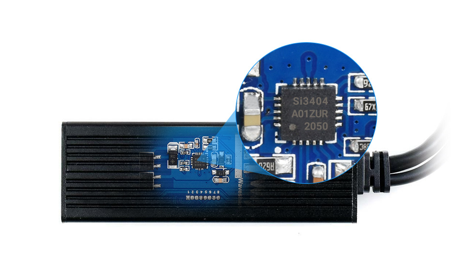
Isolated circuit protection, effectively protecting the powered device
Industrial grade protection case
aluminum alloy case, sturdy and rugged, higher protection level, better heat dissipation 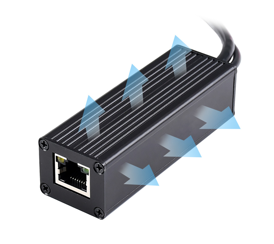
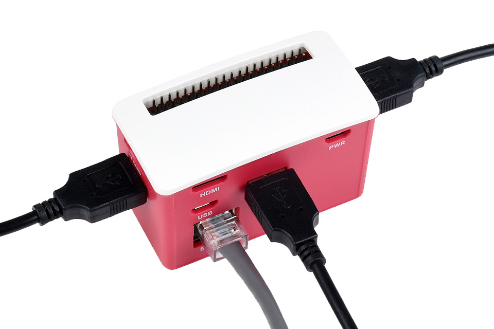
Powering the Raspberry Pi or other 5V-powered network devices by PoE switch
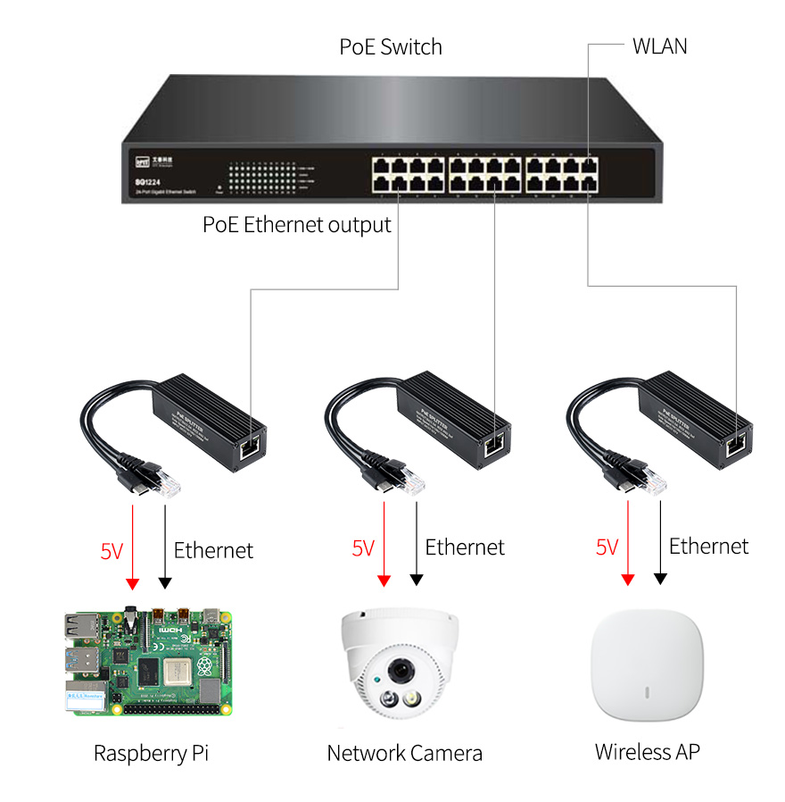
for reference ONLY, Raspberry Pi and switch are NOT included.

This is an E-Ink display HAT for Raspberry Pi, 2.7inch, 264x176 resolution, with embedded controller, communicating via SPI interface.
Due to the advantages like ultra low power consumption, wide viewing angle, clear display without electricity, it is an ideal choice for applications such as shelf label, industrial instrument, and so on.
Features- No backlight, keeps displaying last content for a long time even when power down
- Ultra low power consumption, basically power is only required for refreshing
- Compatible with Raspberry Pi 2B/3B/Zero/Zero W
- Onboard 4x Keys
- SPI interface, for connecting with other controller boards like Raspberry/Arduino/Nucleo, etc.
- Comes with development resources and manual (examples for Raspberry Pi/Arduino/STM32)
Specifications
- Operating voltage: 3.3V
- Interface: 3-wire SPI, 4-wire SPI
- Outline dimension: 85mm × 56mm
- Display size: 57.288mm × 38.192mm
- Dot pitch: 0.217 × 0.217
- Resolution: 264 × 176
- Display color: black, white
- Grey level: 2
- Full refresh time: 6s
- Refresh power: 24mW(typ.)
- Standby power: <0.017mW
- Viewing angle: >170°
Interface
| SYMBOL | DESCRIPTION |
|---|---|
| VCC | 3.3V |
| GND | Ground |
| DIN | SPI MOSI pin |
| CLK | SPI SCK pin |
| CS | SPI chip selection, low active |
| DC | Data/Command selection (high for data, low for command) |
| RST | External reset, low active |
| BUSY | Busy status output, low active |
What's in the box?
2 x RPi screws pack (2pcs)
Resources

Features at a glance
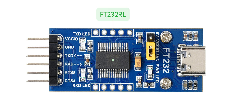
- Original FT232RL onboard
- Supports Mac OS, Linux, Android, WinCE, Windows 7/8/8.1/10/11...
- 3x VCCIO power mode via jumper setting:
- - VCCIO - 5V: 5V output
- - VCCIO - 3.3V: 3.3V output
- - open the jumper: powered from target board (3.3V-5V)
- 3x LED indicators: TXD, RXD, PWR
- Pins accessible on pinheaders: TXD, RXD, RTS#, CTS#
- Other pins are accessible on drilled holes, easily connected to user application system (the pin pitch is compatible with universal prototype board)
FT232 solution
- VCCIO ↔ 3.3V or 5V output (the module is powered from USB, and the onboard jumper should be shorted to 3.3V or 5V)
- GND ↔ GND
- TXD ↔ MCU.RX (signal direction: MCU.RX << FT232 << PC.TX)
- RXD ↔ MCU.TX (signal direction: MCU.TX >> FT232 >> PC.RX)
- RTS ↔ MCU.CTS (signal direction: MCU.CTS << FT232 << PC.RTS)
- CTS ↔ MCU.RTS (signal direction: MCU.RTS >> FT232 >> PC.CTS)
Outline Dimensions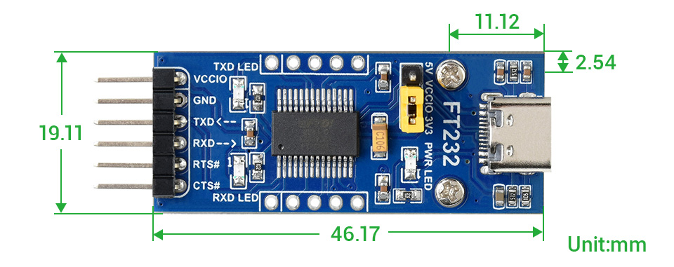

Features at a glance
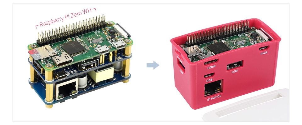
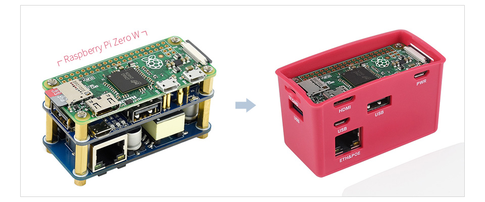
The PoE-ETH-USB-HUB-BOX is a HUB kit with PoE/ETH/USB HUB HAT inside. It is tailored for Raspberry Pi Zero series, small in size, each cut-out of the case is exactly aligned with the connector. The case adopts classic Raspberry Pi red/white color combination, with quality dull polish surface, effectively keeping the Zero away from dust. By using this small HUB BOX and some proper 802.3af-compliant power sourcing equipments, it is possible to provide both network connection and power supply for your Raspberry Pi Zero in only one Ethernet cable, along with 3x extended USB ports.
- Designed for Raspberry Pi Zero, compatible with Zero series boards
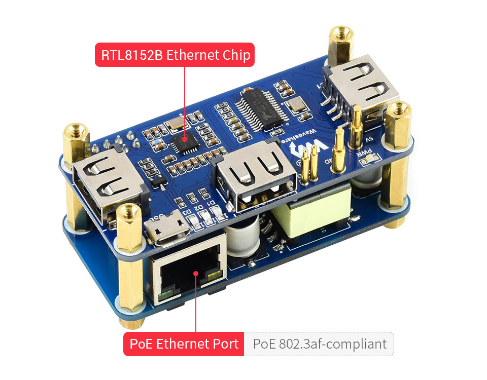
- Incorporates RTL8152B Ethernet chip, with 10M / 100M auto-negotiation RJ45 port
- PoE (Power over Ethernet) feature, 802.3af-compliant
- Fully isolated SMPS (Switch Mode Power Supply)
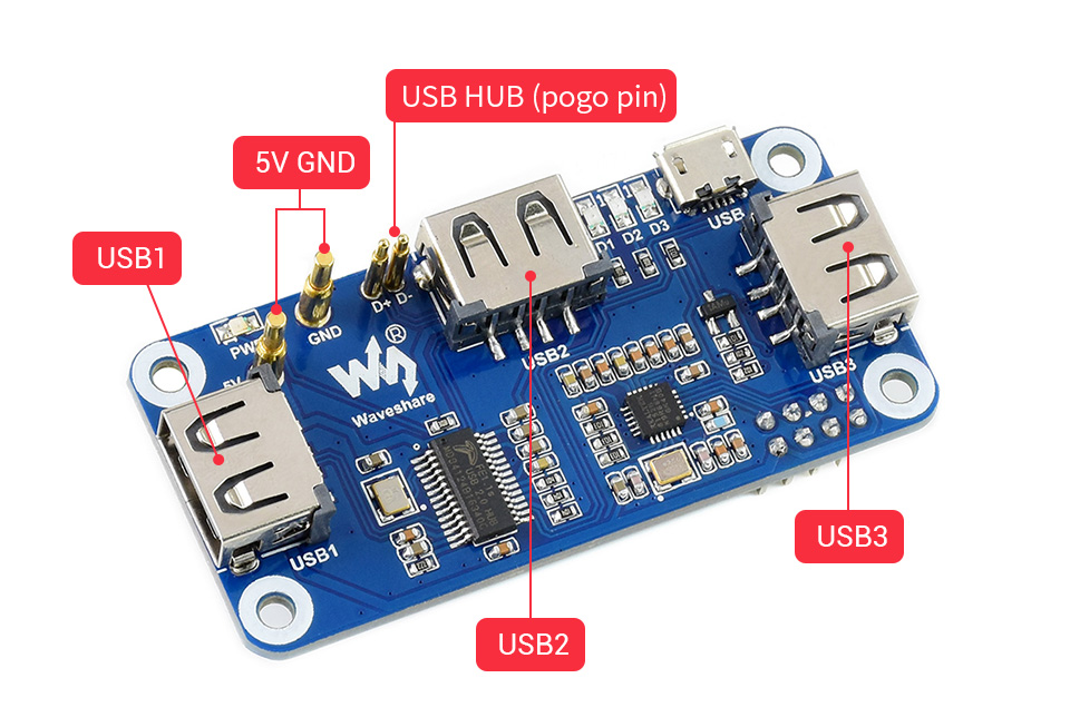
- 3x extended USB ports, compatible with USB 2.0 / 1.1
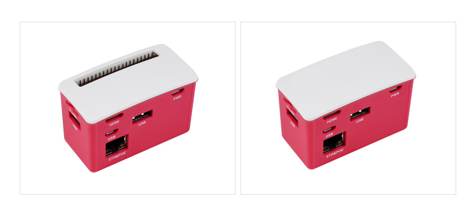
- Angle rounded design, smooth hand feeling, "simple snap" case lid
- Quality ABS material, dull polish surface, anti-fingerprint
- Comes with two different lids, changing as you like
Specifications
- PoE power input: 37V ~ 57V DC in
- Power output: 5V 2.5A DC out
- Network standard: IEEE 802.3af-compliant PoE
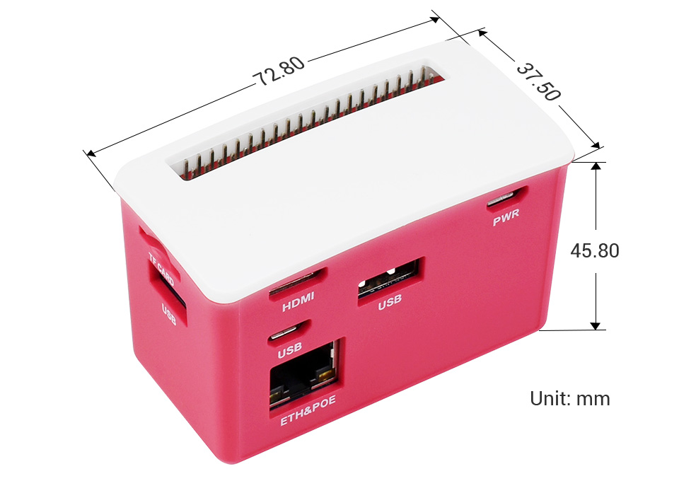
- Dimensions: 72.80 × 37.50 × 45.80 mm
Compatible with Raspberry Pi Zero series
specialized pogo pin connection, dedicated cut-outs for Zero series, plug-and-play
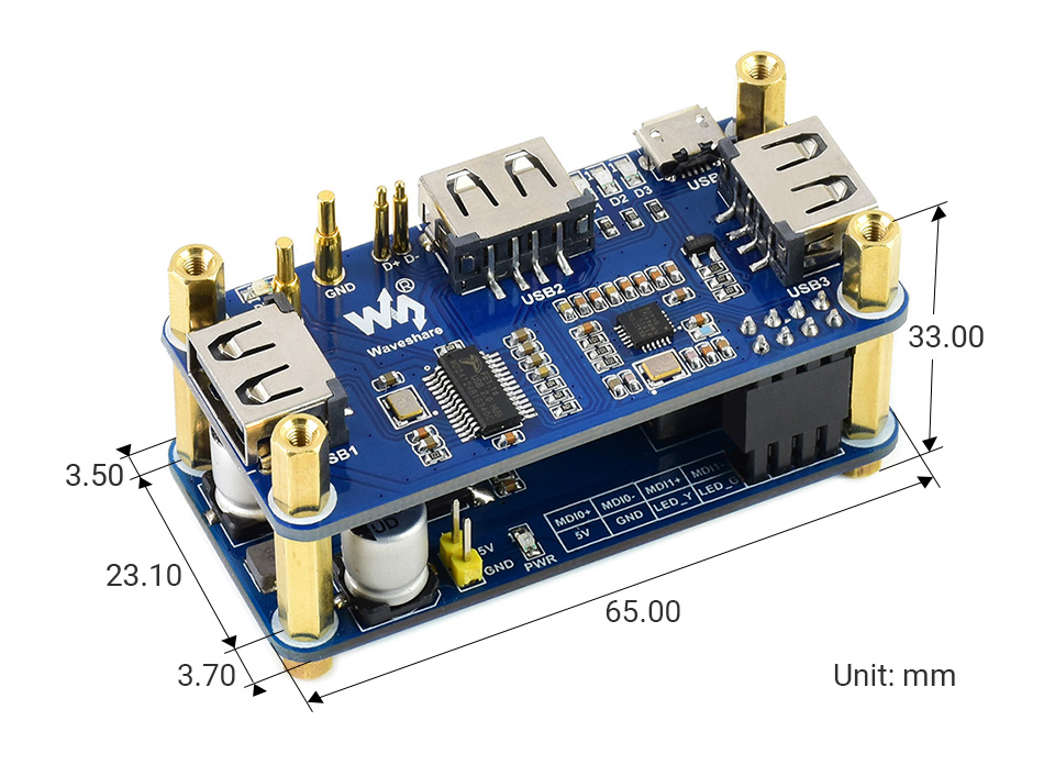
USB1 ~ USB3, compatible with USB 2.0 / 1.1
USB to Ethernet conversion by the RTL8152B chip, 10M / 100M auto-negotiation
"simple snap" design, easy to change, allows attaching other Zero HATs
Application example
Outline dimensions
What's in the box?
1 x ABS case
1 x Rubber feet 4PCS
1 x Screws pack
Resources

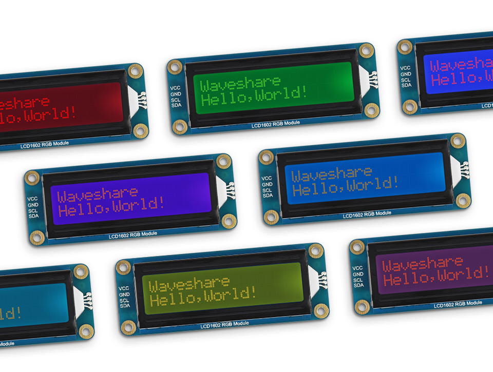
- Incorporates character LCD panel LCD1602
- Adjustable RGB backlight color, up to 16M (2563) backlight colors in theory
- I2C control interface, only two signal pins are required, saving the IO resource
- Compatible with 3.3V/5V operating voltage
- Comes with development resources and manual (Raspberry Pi/Jetson Nano/Arduino examples)
Specifications
- Operating voltage: 3.3 ~ 5V
- LCD controller: AiP31068
- Communication Interface: I2C
- RGB driver: PCA9633
- Display Panel: character LCD
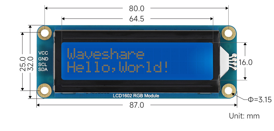
- Display size:64.5 × 16.0mm
- Characters: 16 × 2
- Dimensions: 87.0 × 32.0 × 13.0mm
- Backlight colours: 16M
- Operating voltage: -20 ~ 70℃
Adjustable RGB backlight color - up to 16M colors available
for connecting with host boards like Raspberry Pi / Arduino...
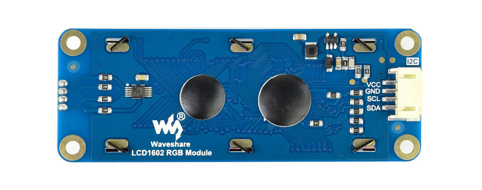
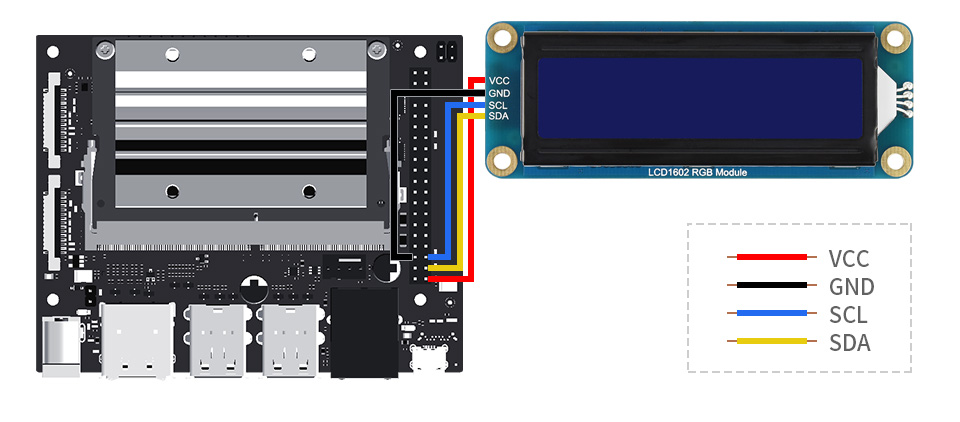
| VCC | 3.3V ~ 5V power input |
| GND | GND |
| SCL | I2C clock pin |
| SDA | I2C data pin |
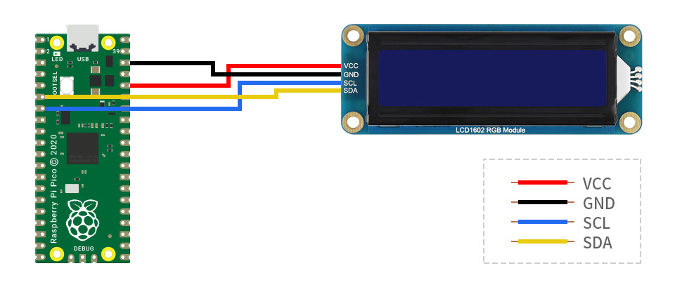
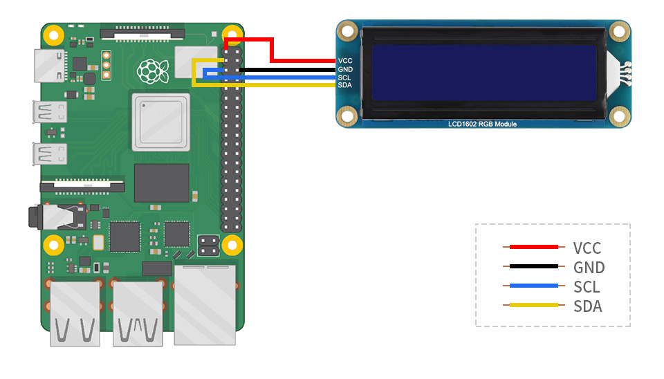
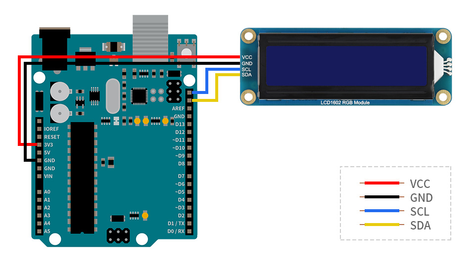
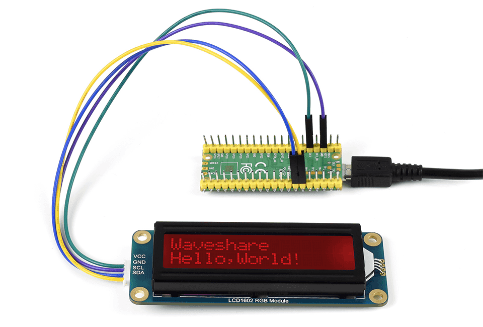
Hardware connection
connecting with Raspberry Pi Pico
connecting with Raspberry Pi
connecting with Arduino board
connecting with Jetson Nano Developer Kit

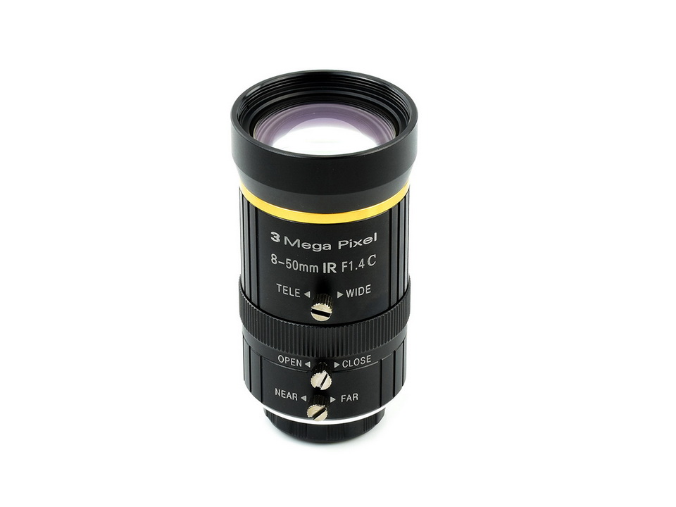
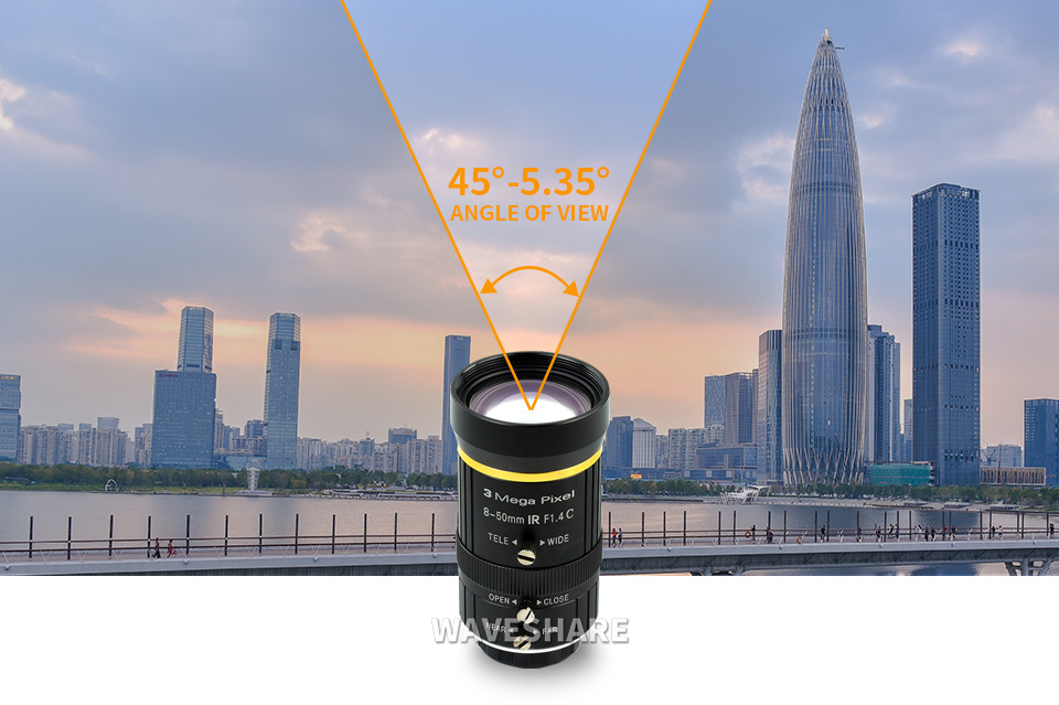
8-50mm adjustable focal length, flexible photo composition at your will
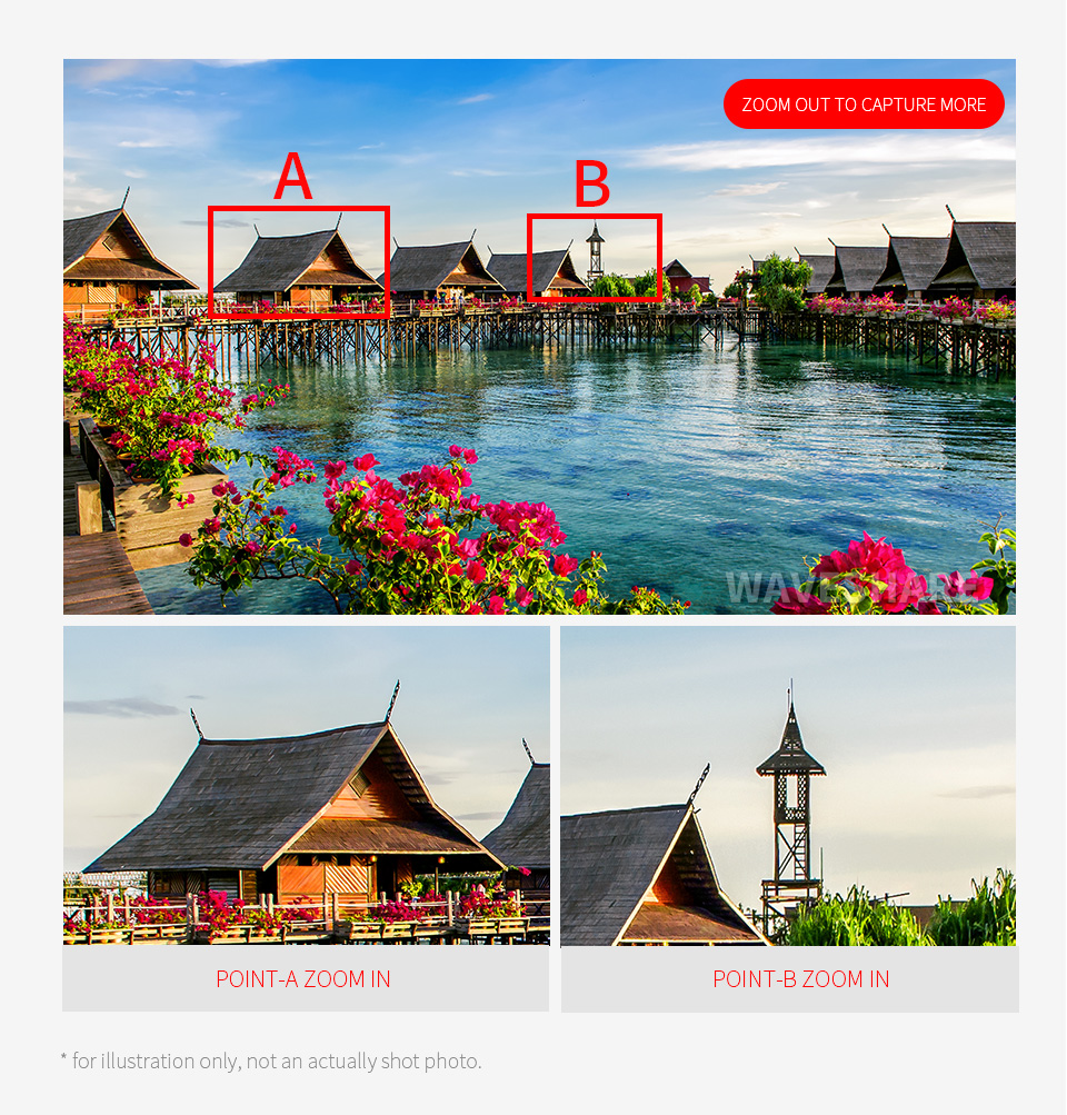
Adjustable focal length
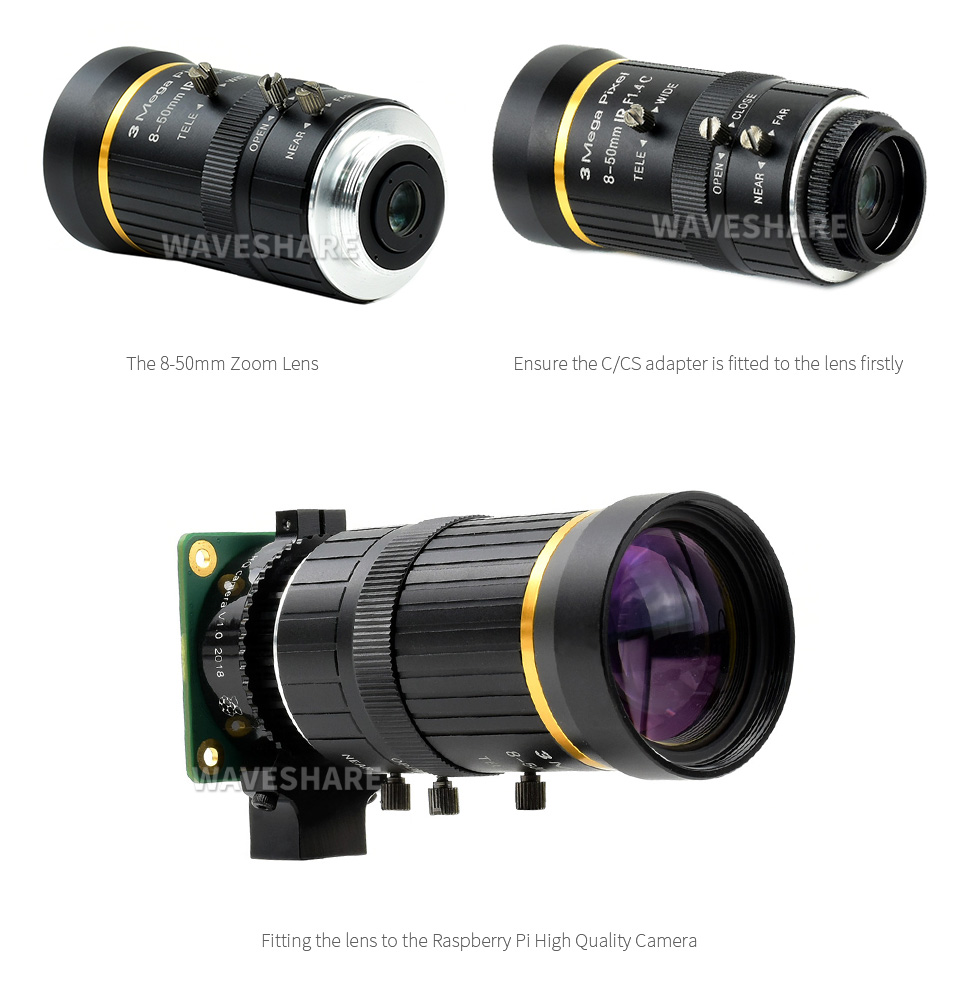
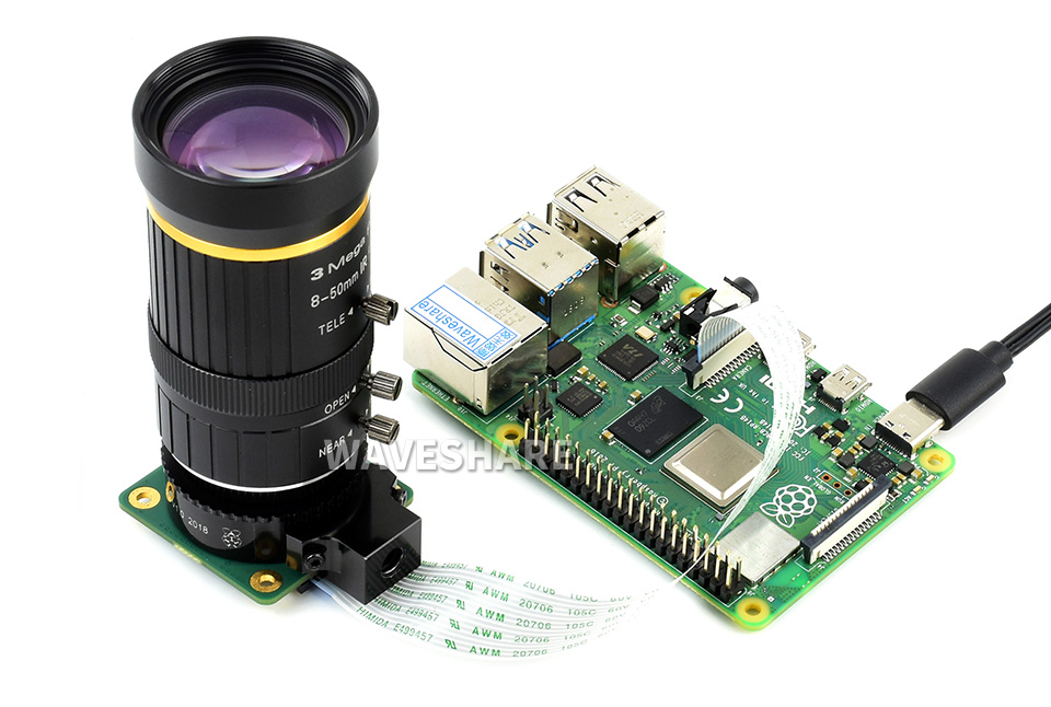
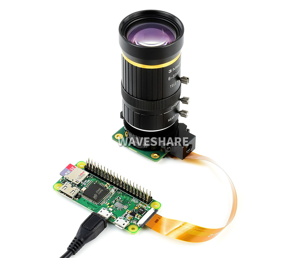
- Raspberry Pi, and High Quality Camera in the photos are NOT included
- To use with Raspberry Pi Zero, you need to buy an additional Raspberry Pi Zero v1.3 Camera Cable
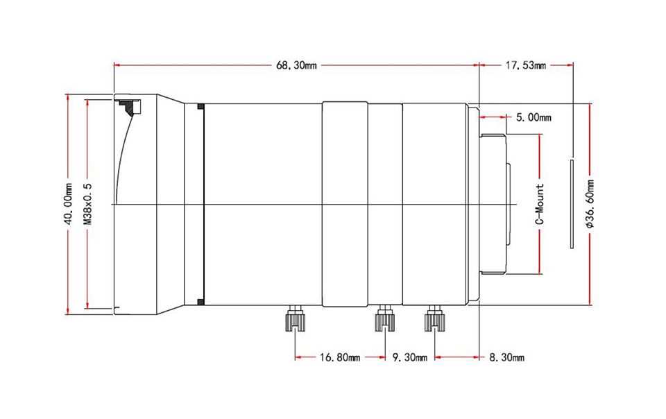
Outline Dimensions
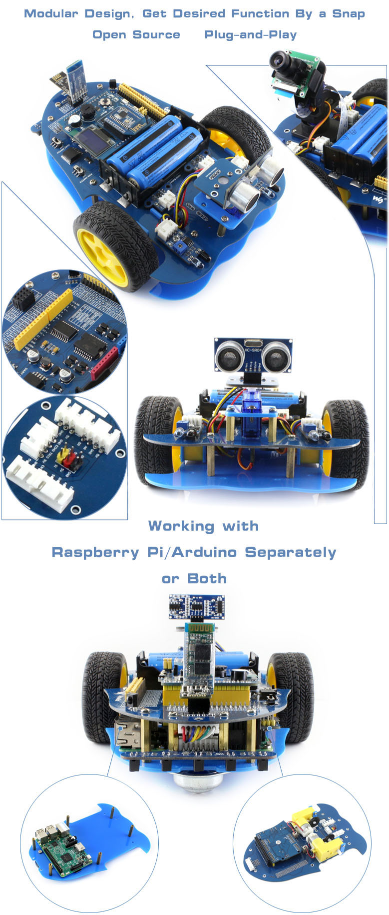
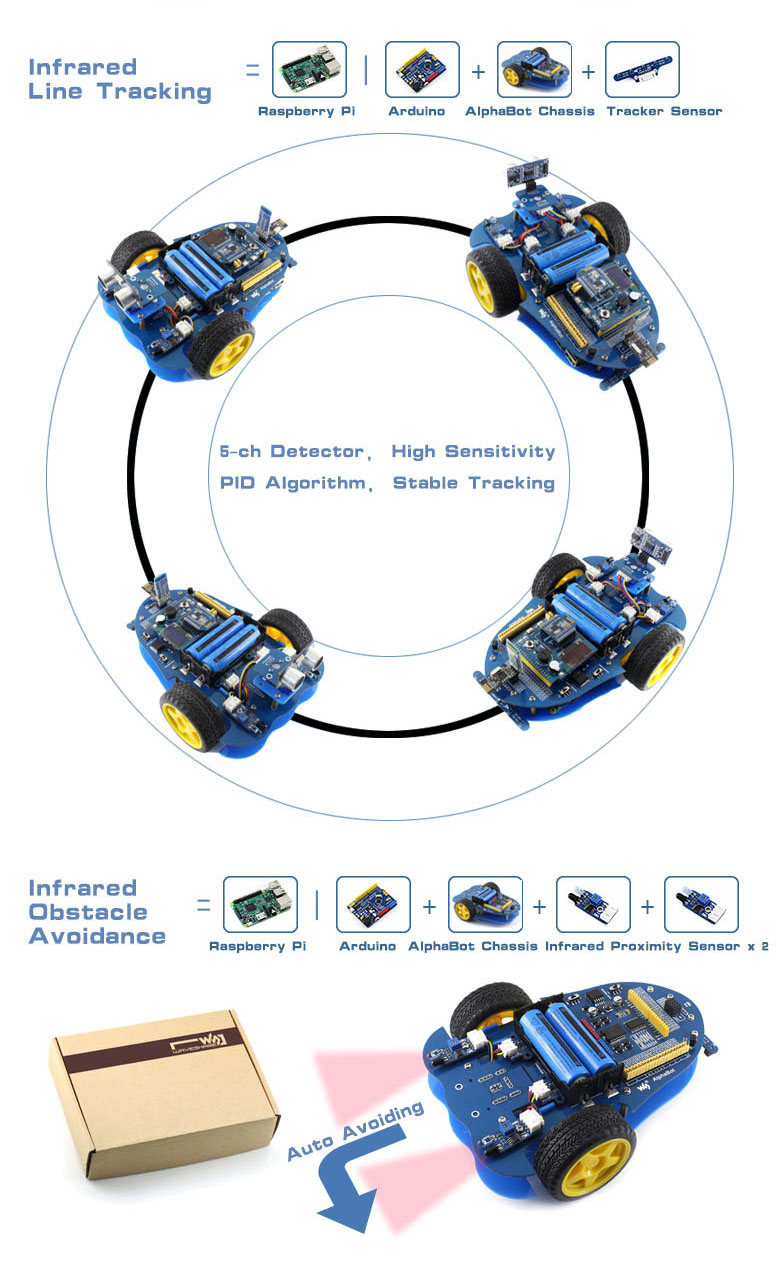
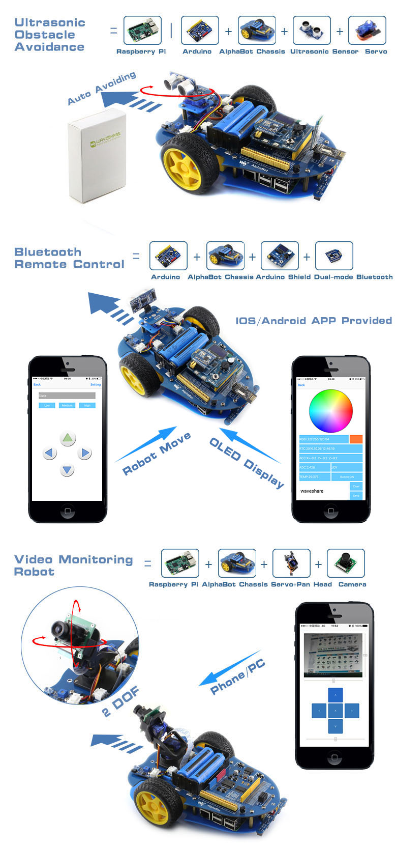
AlphaBot is a robotic development platform compatible with Raspberry Pi and Arduino. It consists of the AlphaBot mainboard, the mobile chassis, and everything required to get it moving.
Just connecting a controller board, Raspberry Pi or Arduino, and combined with our open source example code, now it's all ready to start your robotic exploration: line tracking, obstacle avoidance, video monitoring, WiFi/Bluetooth/ZigBee/Infrared remote control, etc.
- Raspberry Pi/Arduino interfaces, works with either one separately, or both
- Arduino extend header, supports Arduino shields
- Modular design, plug-and-play modules like line tracking, obstacle avoidance, speed measuring, etc. eliminating the trouble of connecting mess wires.
- LM298P motor driver with diode protection circuit, more safety
- LM2596 voltage regular, provides stable 5V power to the Raspberry Pi/Arduino
- TLC1543 AD acquisition chip, allows the Pi to use analog sensors
What's on the AlphaBot Mainboard
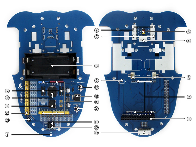
- Raspberry Pi interface: for connecting Raspberry Pi
- Arduino interface: for connecting Arduino
- Motor interface
- Ultrasonic module interface
- Servo module interface
- Obstacle avoidance module interface
- Speed measuring interface
- Battery holder: supports 18650 batteries
- Reserved power input (not soldered): for connecting other external power supply
- Arduino expansion header: for connecting Arduino shields
- UART interface: for connecting Bluetooth module, to control the robot remotely via Bluetooth
- SPI interface: for connecting NRF24L01 wireless module
- Line tracking module interface
- TLC1543: 10-bit AD acquisition chip, allows the Pi to use analog sensors
- LM298P: dual H bridge motor driver chip, up to 2A current
- Anti-reverse diode
- Power switch
- LM2596: 5V regulator
- Power indicator
- UART switch: turn on to enable serial communication between Raspberry Pi and Arduino
- IR receiver: control the robot remotely via infrared
- Raspberry Pi/Arduino selection: select the Raspberry Pi or Arduino to control the robot peripherals

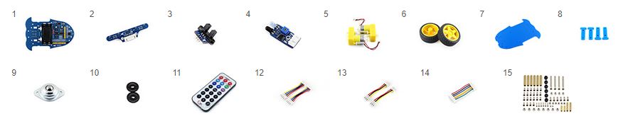
What's in the box?
Please note that the battery length SHOULD be less than 67mm, some batteries with protection plate in the market are NOT supported
- AlphaBot mainboard x1
- Tracker Sensor x1
- Photo Interrupter Sensor x2
- Infrared Proximity Sensor x2
- Motor with gearbox 2PCS x1
- AlphaBot wheel 2PCS x1
- AlphaBot acrylic chassis x1
- Motor mounting plate 4PCS x1
- omni-direction wheel x1
- 20-slots encoder disk 2PCS x1
- IR remote controller x1
- XH2.54 4cm 4Pin 2PCS x1
- XH2.54 4cm 3Pin 2PCS x1
- XH2.54 4cm 7Pin x1
- AlphaBot screws x1
Resources

SAFETY PRECAUTIONS
Li-ion and Li-po batteries are quite unstable. They may cause fire, personal injury, or property damage, if they're not properly recharged or used.
Do not reversely connect the polarities when recharging or discharging the battery.
Do not use inferior charger/charging panel to recharge the battery.
Do not mix use old batteries with new ones, avoid using batteries of different brands.
When buying a Lithium battery, you should always make sure the battery specification is compatible with the expansion board. Choose batteries from formal manufacturers and ensure the batteries will work stably and safely by aging test.
Lithium batteries have limited cycle life, they will also deteriorate as time goes by. Should be replaced with new ones when the batteries reaching their max cycle life, or working over two years, whichever comes first.
Batteries should be stored carefully and properly, keep it away from inflammables and explosives articles, away from children, avoid any safety accident caused by careless storage.
Features
The Solar Power Manager (C) is compatible with general 6V~24V solar panels. It can recharge the 18650 rechargeable Li-ion batteries through solar panel or USB TYPE-C connection, and provides 5V / 3A regulated output (with multi protocols support including PD/QC/FCP/PE/SFCP).
The module features MPPT (Maximum Power Point Tracking) function and multi protection circuits, therefore, it is able to keep operating with high-efficiency, stability, and safety. It is suitable for solar powered, low-power IoT, and other environmental protection projects.
- Supports MPPT (Maximum Power Point Tracking) function, maximizing the efficiency of the solar panel.
- Flexible battery recharging: from solar panel or USB TYPE-C power adapter.
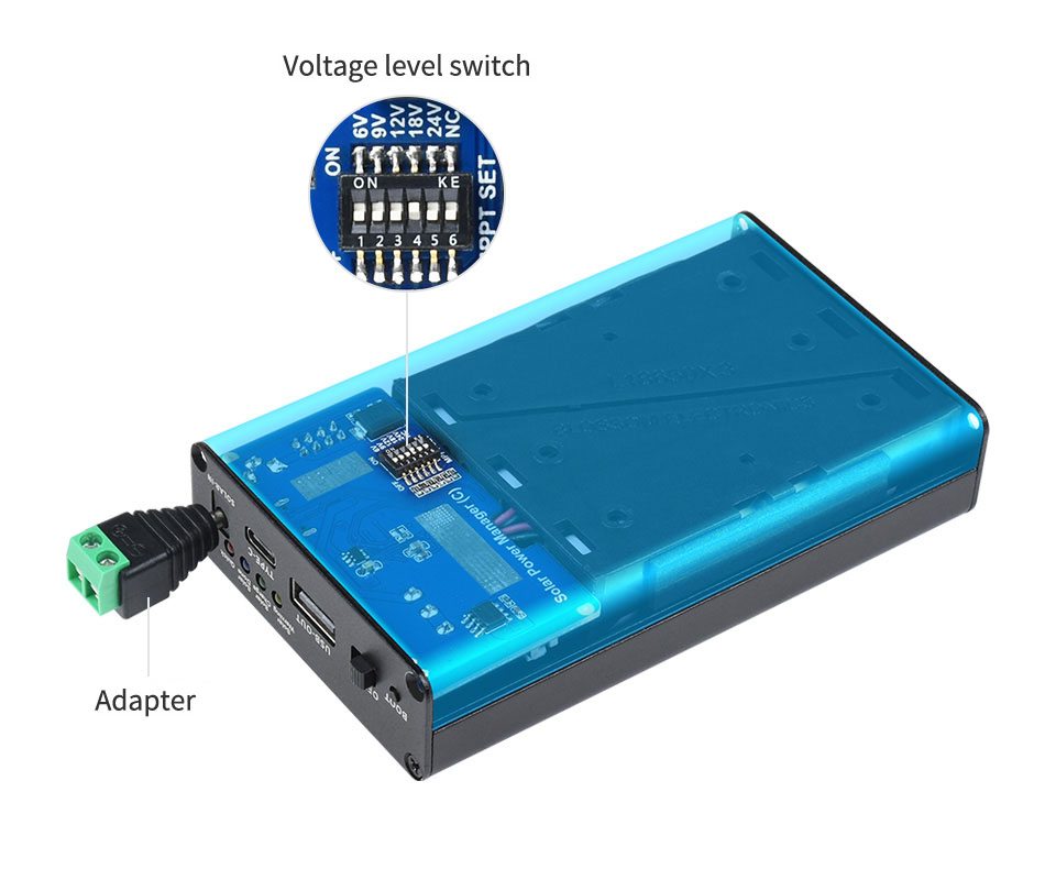
- Compatible with 6V~24V solar panels, DC-002 jack input or screw terminal input
- Onboard MPPT SET switch, select the level closed to input level to improve recharging efficiency
- Onboard aluminum electrolytic capacitor and SMD ceramic capacitor, reducing the ripple, stable performance
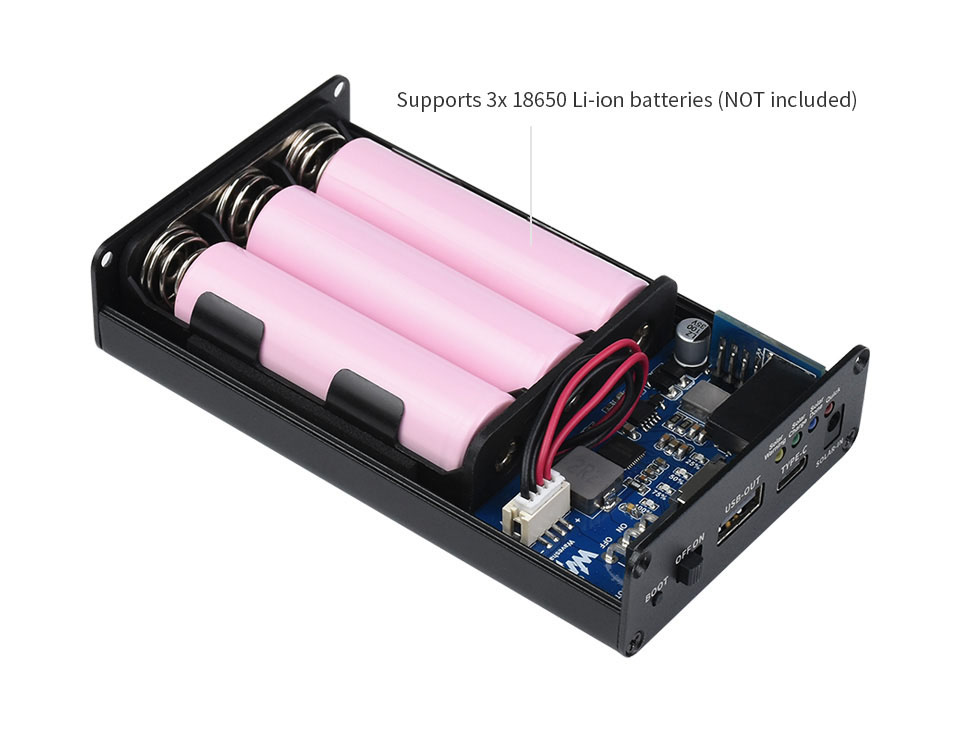
- Embedded battery holder, supports 3x 18650 rechargeable Li-ion batteries
- Several LED indicators, for monitoring the status of solar panel and battery
- Multi protection circuits: over charge / over discharge / reverse-proof / over heat / over current, stable and safe to use
Supports 6V~24V solar panels
5-level voltage switch, for setting solar panel input voltage to improve efficiency
3x 18650 batteries support(not included)
Embedded battery holder for rechargeable Li-ion batteries
Application example
solar-powered control system for MCUs / development boards like:
Raspberry Pi / Jetson Nano / Arduino...
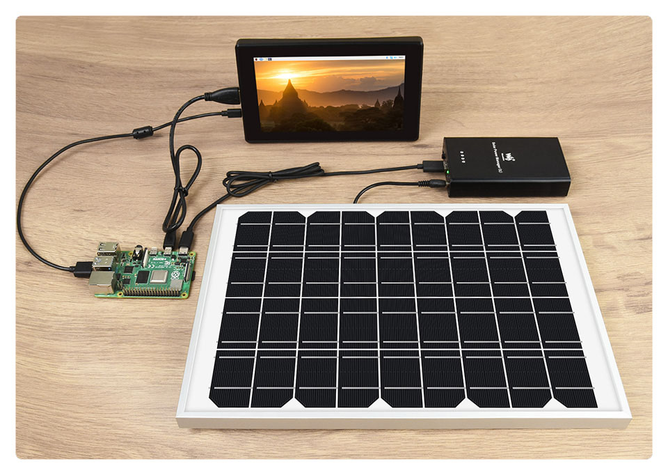
Note: for reference ONLY, the Raspberry Pi, display, solar panel are NOT included.
Resources introduction
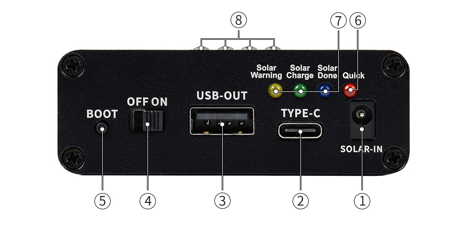
- Solar panel input
recharging through DC-002 jack or screw terminal - TYPE-C recharging/output port
supports 5V power adapter for recharging
supports PD protocol quick charge adapter
supports PD/QC/FCP/PE/SFCP multi protocols output - USB output port
5V/3A regulated output
supports PD/QC/FCP/PE/SFCP multi protocols output
- Battery on/off switch
- BOOT button
- Quick charge indicator
- Solar panel status indicators
Solar Warning: lights up if solar panel is reversed
Solar Charge: lights up when recharging from solar panel
Solar Done: lights up when the battery is fully recharged - Battery life indicators
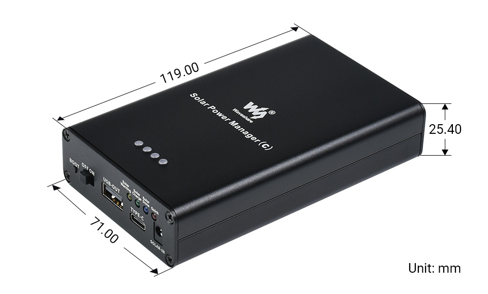
Outline Dimensions
What's in the box?
1 x solar manager
Need batteries? You will find our battery selection here
Resources

Note: the CM4 is NOT included. Please buy it separately if necessary.
The Nano Base Board (B) For Raspberry Pi Compute Module 4, is the Same Size As The CM4 and is suitable For Evaluating The Raspberry Pi CM4 Or Being Integrated Into End Products.
This module is Compact, Yet Complete, featuring: Standard CM4 Socket, 40PIN GPIO, Gigabit Ethernet, USB2.0, DSI, CSI, 3.5mm Audio Jack...
Specifications
CM4 SOCKET - suitable for all variants of Compute Module 4
NETWORKING - Gigabit Ethernet RJ45 connector
CONNECTOR - Raspberry Pi 40PIN GPIO header × 1
USB - USB 2.0 Type A connector × 1
DISPLAY - MIPI DSI port × 1 (15pin 1.0mm FPC connector)
CAMERA - MIPI CSI-2 port × 1 (15pin 1.0mm FPC connector)
VIDEO - Mini HDMI port × 1, supports 4K 30fps output
AUDIO - 3.5mm jack
STORAGE - Micro SD card socket for Compute Module 4 Lite (without eMMC) variants
POWER INPUT - 5V
DIMENSIONS - 56 × 41mm
What's On Board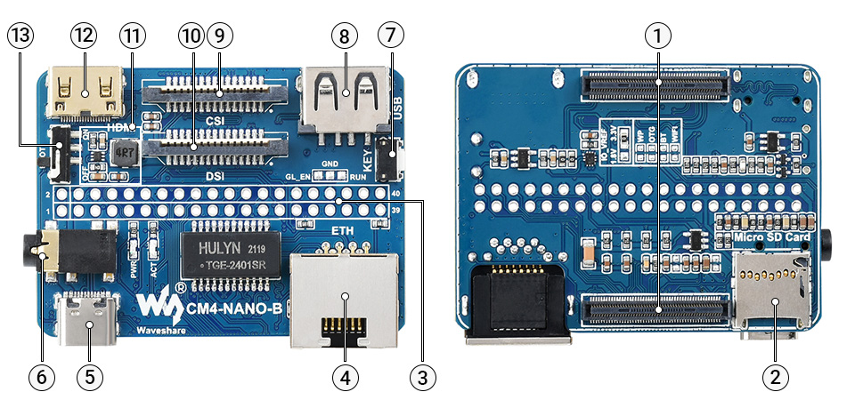
- CM4 socket
suitable for all variants of Compute Module 4 - Micro SD card slot
for connecting a Micro SD card with pre-burnt image (Lite variant ONLY) - 40PIN GPIO header
for connecting sorts of HATs - Gigabit Ethernet RJ45 connector
- Power supply / Programming
5V power supply, or used for eMMC burning - 3.5mm audio jack
- User button
- USB2.0 connector
for connecting sorts of USB devices
- CSI connector
MIPI CSI camera interface - DSI connector
MIPI DSI display interface - MP1658
- Mini HDMI connector
supports 4K 30fps output - BOOT switch
ON: Switch USB to Type C interface, will enter download mode when powered on (configured as a large-capacity disk through RPI boot)
OFF: Switch USB to Type A interface, will not enter download mode when powered on (booted from eMMC or Micro SD card)
Outline Dimensions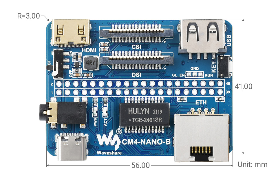
What's in the box?
1 x CM4-NANO-B

1 x 2*20PIN color-coded straight pin header

Resources
WIKI: CM4-NANO-B

- It usually takes about 0.3s for partial refresh
- Pi Header: standard Raspberry Pi 40PIN GPIO extension header, supports Raspberry Pi series boards
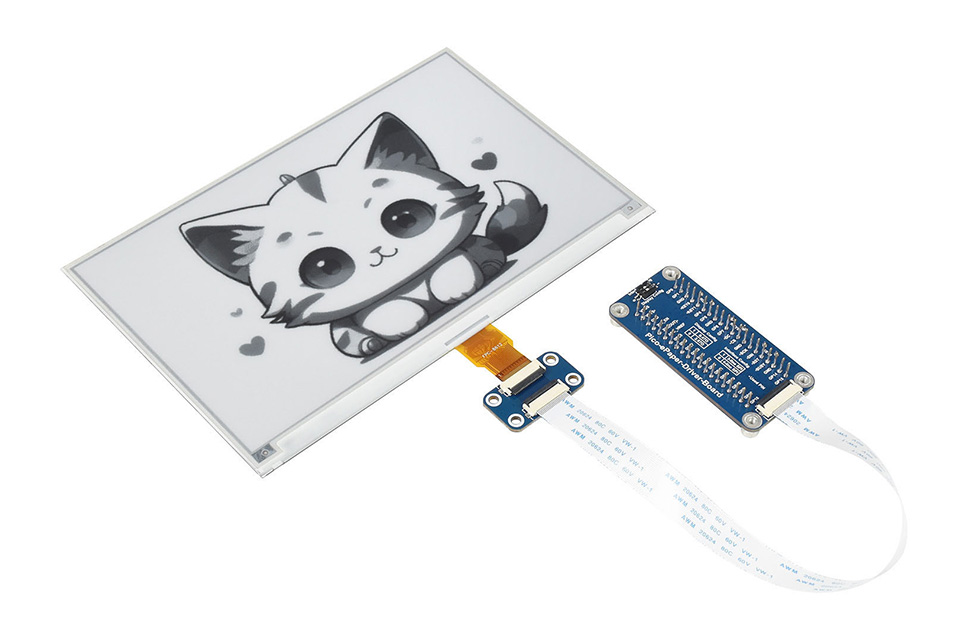
This is an E-Ink display HAT for Raspberry Pi, 7.5inch, 800×480 resolution, with embedded controller, communicating via SPI interface.
Due to the advantages like ultra low power consumption, wide viewing angle, clear display without electricity, it is an ideal choice for applications such as shelf label, industrial instrument, and so on.
Features- No backlight, keeps displaying last content for a long time even when power down
- Ultra low power consumption, basically power is only required for refreshing
- Standard Raspberry Pi 40PIN GPIO extension header, supports Raspberry Pi series boards, Jetson Nano
- SPI interface, for connecting with other controller boards like Raspberry/Arduino/Nucleo, etc.
- Onboard voltage translator, compatible with 3.3V/5V MCUs
- Comes with development resources and manual (examples for Raspberry Pi/Jetson Nano/Arduino/STM32)
Specifications
- Operating voltage: 3.3V~5V
- Interface: SPI
- Outline dimension: 170.2mm × 111.2mm
- Display size: 163.2mm × 97.92mm
- Dot pitch: 0.205 × 0.204
- Resolution: 800×480
- Display color: black, white
- Grey scale: 2
- Full refresh time: 5s
- Refresh power: 38mW(typ.)
- Standby power: <0.017mW
- Viewing angle: >170°
Revision History
Revision V2 has been released on 2019.11, the resolution is upgraded to 800×480, from 640×384 of V1. The hardware and interface of V2 are compatible with V1, however, the related software should be updated.
| SYMBOL | DESCRIPTION |
|---|---|
| VCC | 3.3V~5V |
| GND | Ground |
| DIN | SPI MOSI pin |
| CLK | SPI SCK pin |
| CS | SPI chip selection, low active |
| DC | Data/Command selection (high for data, low for command) |
| RST | External reset, low active |
| BUSY | Busy status output, low active |
Dimensions
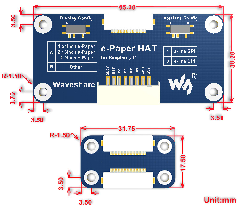
What's in the box?
- 7.5inch e-Paper x1
- e-Paper Driver HAT x1
- RPi screws pack (2pcs) x1
- PH2.0 20cm 8Pin x1
 2
2 3
3 4
4
Resources

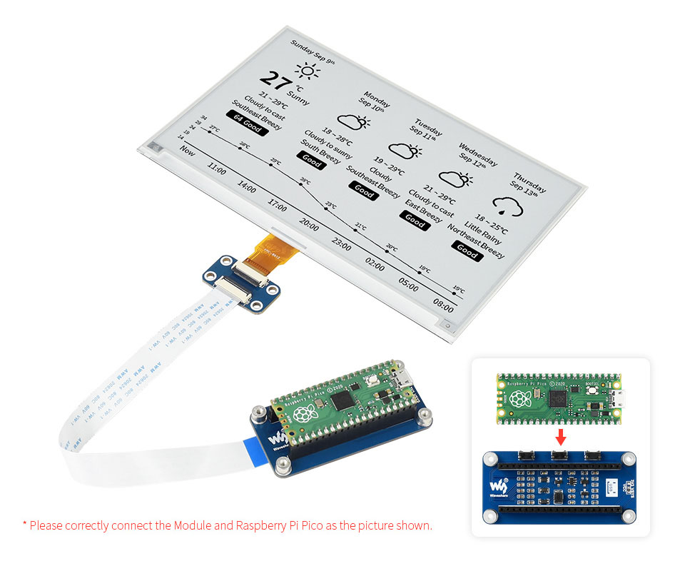
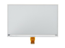
7.5inch E-Paper E-Ink Display Module For Raspberry Pi Pico, 800×480 Pixels, Black / White, SPI Interface. Low Power, Wide Viewing Angle, Paper-Like Effect Without Electricity. Ideal for price tags, shelf labels, industrial instruments...
- No backlight, keeps displaying last content for a long time even when power down
- Ultra low power consumption, basically power is only required for refreshing
- SPI interface, requires minimal IO pins
- 2x user buttons and 1x reset button for easy interacting
- Comes with development resources and manual (Raspberry Pi Pico C/C and MicroPython examples)
| OPERATING VOLTAGE | 3.3V | DISPLAY COLOR | black, white |
|---|---|---|---|
| RESOLUTION | 800×480 pixels | GREY SCALE | 2 |
| INTERFACE | 3-wire SPI, 4-wire SPI | VIEWING ANGLE | >170° |
| PARTIAL REFRESH TIME | N/A | FULL REFRESH TIME | 5s |
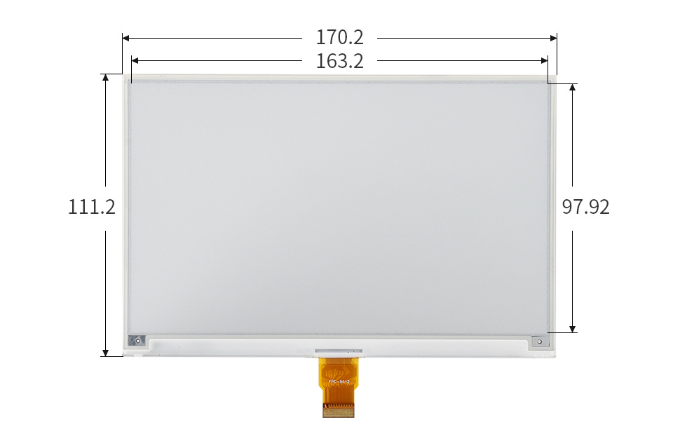
| OUTLINE DIMENSIONS | 170.2 × 111.2mm | DISPLAY SIZE | 163.2 × 97.92mm |
| REFRESH POWER | 26.4mW (typ.) | STANDBY CURRENT | <0.01uA (almost none) |
| DOT PITCH | 0.204 × 0.204mm |
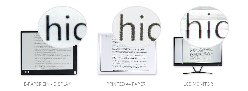
Advantages Of EINK
E-paper display utilizes microcapsule electrophoretic technology for displaying, the principle is: charged particles suspended in clear fluid will move to sides of microcapsule when electric field is applied, making the microcapsule become visible by reflecting ambient light, just as traditional printed paper.
E-paper display will clearly display images/texts under lamplight or natural light, requires no backlight, and features nearly up to 180° viewing angle. It is usually used as e-reader due to its paper-like effect.
Raspberry Pi Pico Header Compatibility
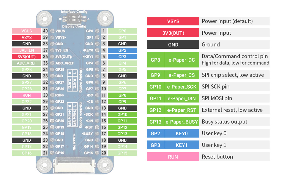
Onboard Female Pin Header For Direct Attaching To Raspberry Pi Pico
2x User Buttons And 1x Reset Button For Easy Interacting
Extended Pico Header, Allows Attaching More Modules For Pico
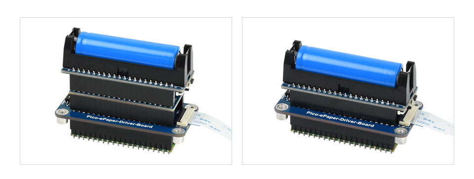
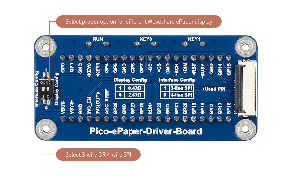
Onboard Switch For Using With Multi E-Paper Displays, Or Selecting SPI Bus
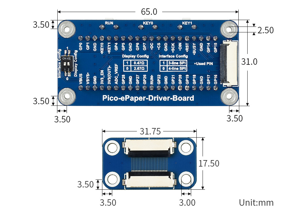
Outline Dimensions
What's in the box?
- 7.5inch e-Paper x1
- Pico-ePaper-Driver-Board x1
- Standoff pack x1
 2
2 3
3
Resources & Services

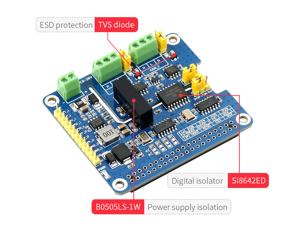
Thanks to multi onboard protection circuits, including 500W lightningsurge, ESD protection, short circuit protection, and electrical isolation, it make the communication more safe and more reliable.
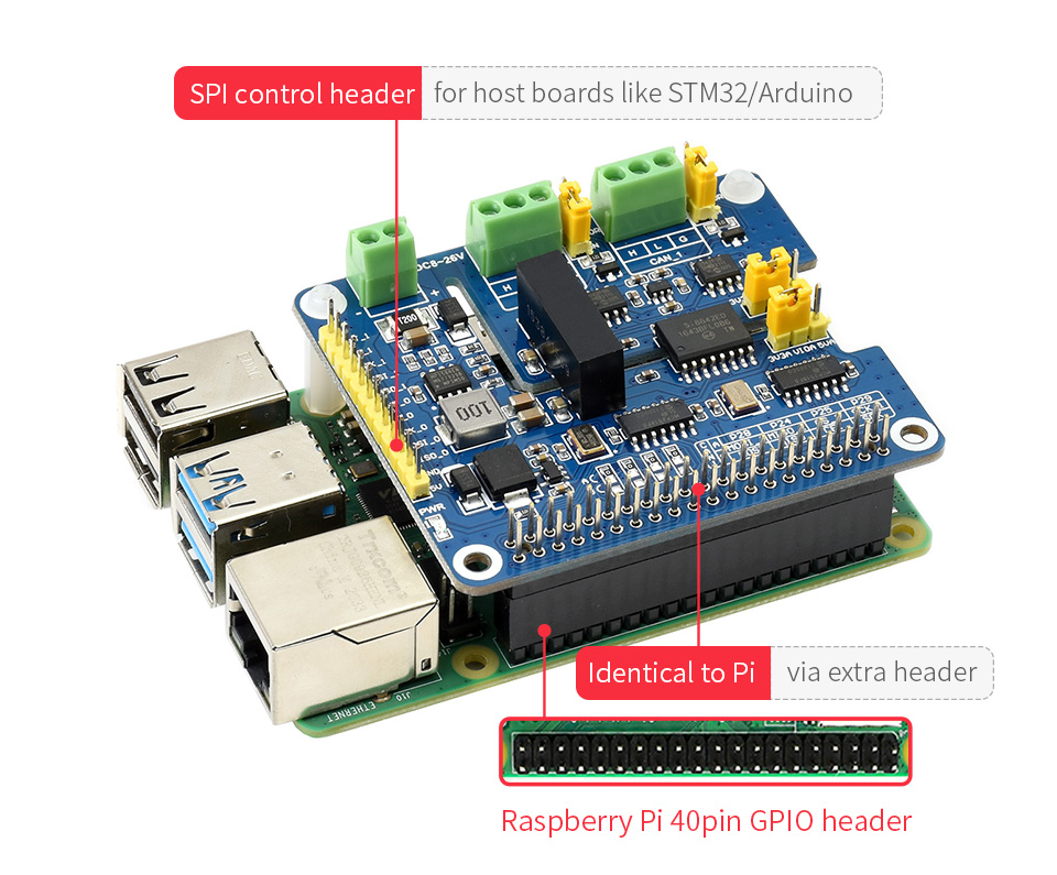
- Standard Raspberry Pi 40PIN GPIO extension header, supports Raspberry Pi series boards, Jetson Nano
- Supports both traditional CAN2.0 and CAN FD protocols
- Breakout SPI control pins, for connecting with host control boards like STM32/Arduino
- Onboard electrical isolation, up to 5KV isolated voltage, stable operation, higher anti-interference capability
- Onboard lightningproof, ESD protection, short circuit protection, more safe communication
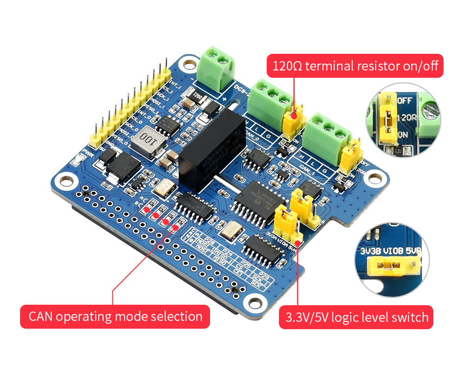
- Onboard voltage translator, select 3.3V/5V operating voltage by jumper
- Onboard 120Ω terminal resistor, configured by jumper
- Comes with development resources and manual (examples for Raspberry Pi/Arduino)
Specifications
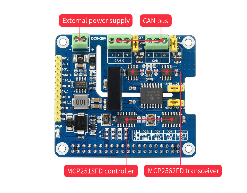
- CAN CONTROLLER: MCP2518FD
- CAN TRANSCEIVER: MCP2562FD
- CONTROL BUS: SPI
- POWER SUPPLY: External power supply terminal OR Raspberry Pi
- SCREW TERMINALINPUT VOLTAGE: DC 8~26V
- OPERATING VOLTAGE: 5V
- LOGIC LEVEL: 3.3V/5V
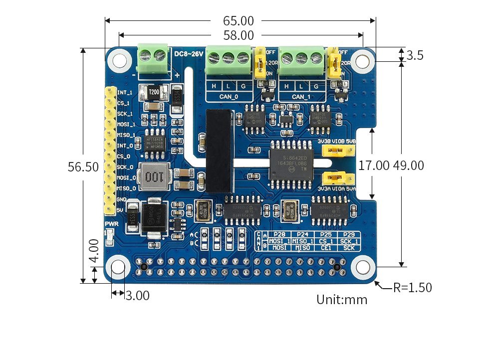
- DIMENSIONS: 65.0 × 56.5mm
What Can It Do?
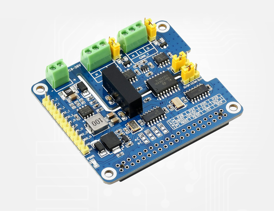
Enable Isolated And Stable CAN FD Capability For Your Raspberry Pi
Designed For Raspberry Pi Series
Standard Raspberry Pi 40PIN GPIO Header, Customized For Raspberry Pi Series Boards
2-Channel CAN Support
MCP2518FD CAN Controller MCP2562FD CAN Transceiver
Electrical Isolation Circuitry Safe & Stable
SM24CANB TVS Diode, ESD Protection, Transient Peak Voltage Protection
Flexible With Handy Jumpers
Easily Select 3.3V / 5V Operating Voltage, Or Enable/Disable 120Ω Terminal Resistor, Via Onboard Jumpers
What's On Board?
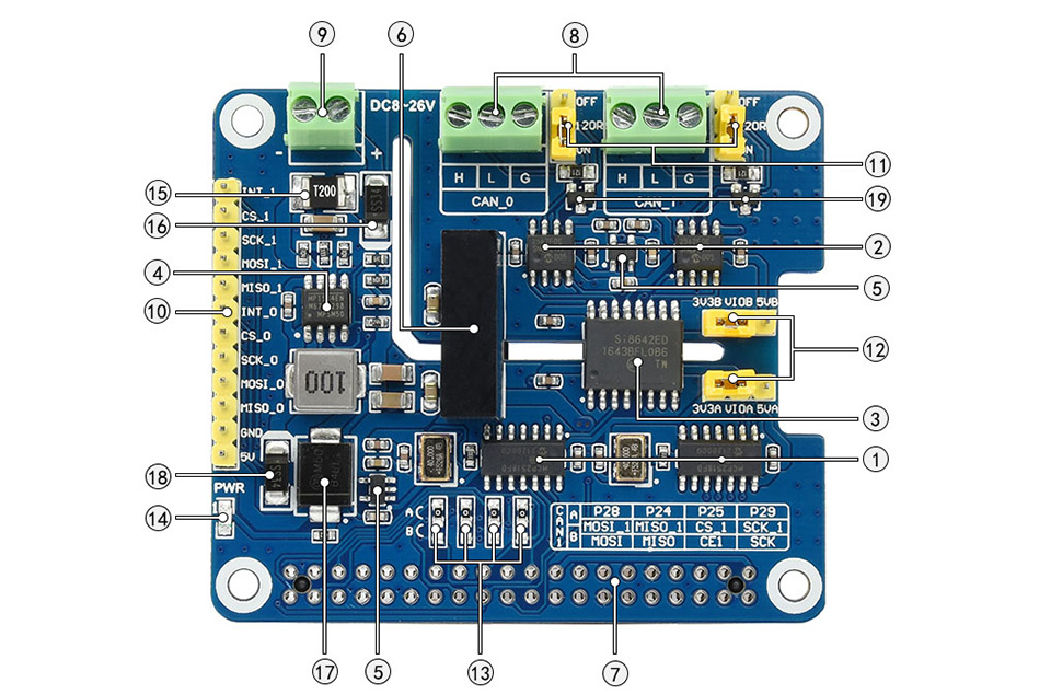
- MCP2518FD controller
- MCP2562FD transceiver
- SI8642ED digital isolator
- MP1584EN power chip
- RT9193-33 power chip
- B0505LS-1W power supply isolation module
- Standard Raspberry Pi 40PIN GPIO header
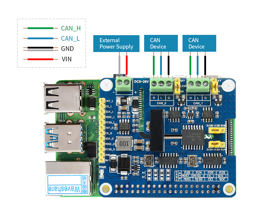
- CAN bus screw terminal
- External power supply terminal
8~26V DC input - MCU control pins
for use with host boards like Arduino
- 120Ω terminal resistor switch
- 3.3V/5V logic level switch
- CAN operating mode selection
A: CAN_0 and CAN_1 use two separated SPI (default)
B: CAN_0 and CAN_1 share a single SPI - Power indicator
- 2A fast resettable fuse
- Power supply reverse-proof diode
- Power supply flow backward proof diode
- Freewheeling diode
- SM24CANB TVS diode
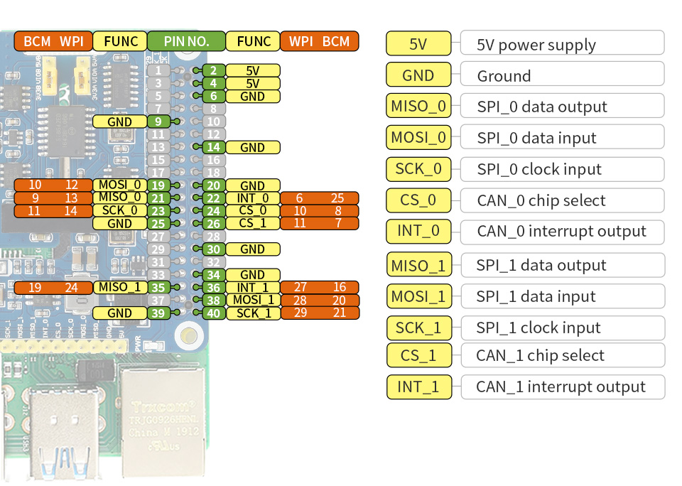
Pinout Definition
Outline Dimensions
What's in the box?
1 x CAN FD Expansion HAT for Raspberry P
Resources

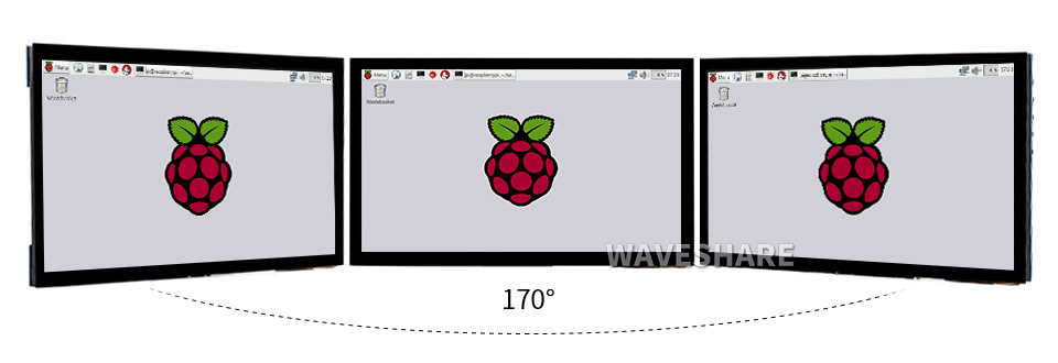
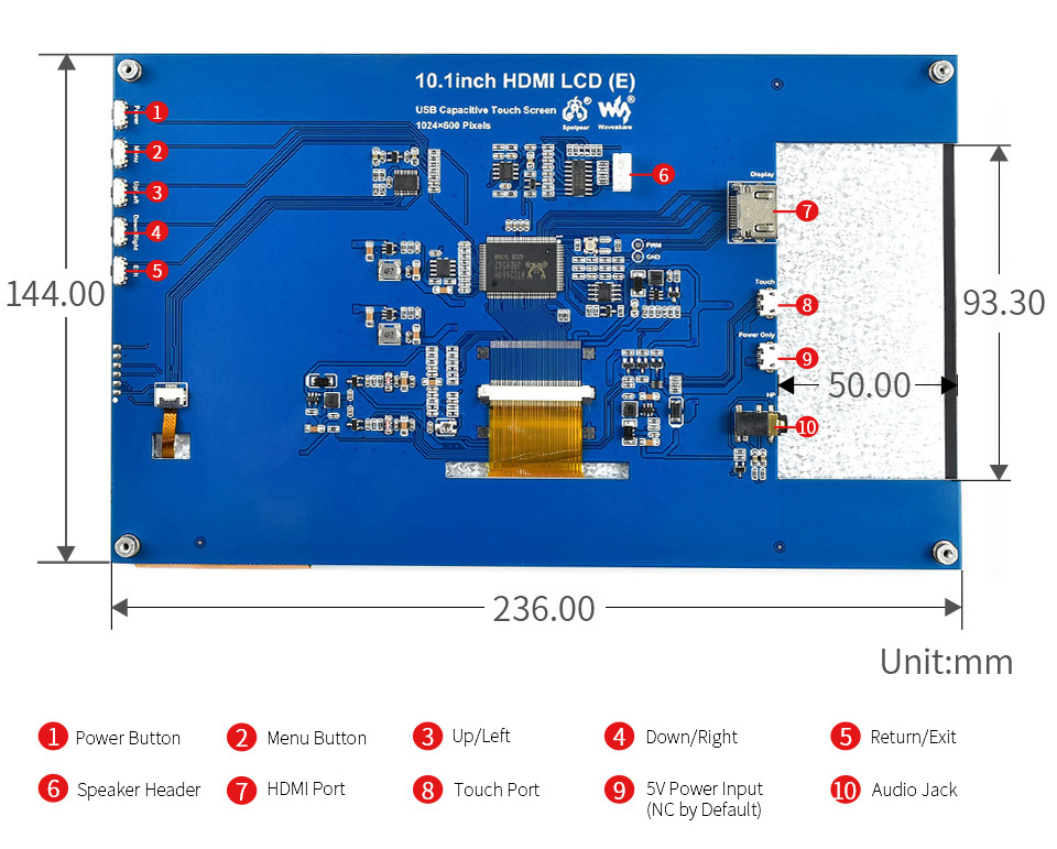
Size 10.1" | Resolution 1024×600 1024×600 | Display Port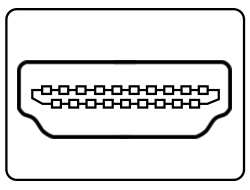 HDMI HDMI | Display Panel IPS IPS | Viewing Angle 170° 170° |
Touch Type Capacitive Capacitive | Touch Points 10-Points 10-Points | Touch Port USB USB | Touch Panel Toughened Glass Toughened Glass | Touch Panel Tech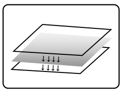 Fully Laminated Fully Laminated |
OSD Menu Brightness/Contrast Brightness/Contrast | Audio Output1 3.5mm Jack 3.5mm Jack | Audio Output2 4PIN Header 4PIN Header | Gaming Xbox360/PS4/Switch Xbox360/PS4/Switch |
Supports Raspbian, 10-points touch, driver free
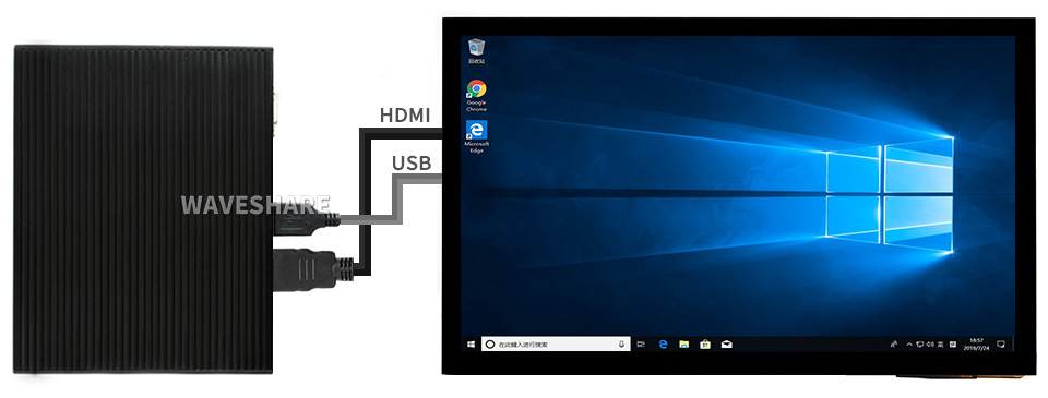
Supports Ubuntu / Kali / WIN10 IoT, single point touch, driver free
Supports Retropie, driver free
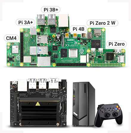
Supports all versions of Raspberry Pi
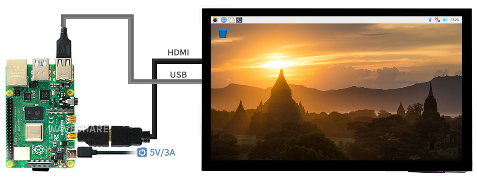
Working With Raspberry Pi 4
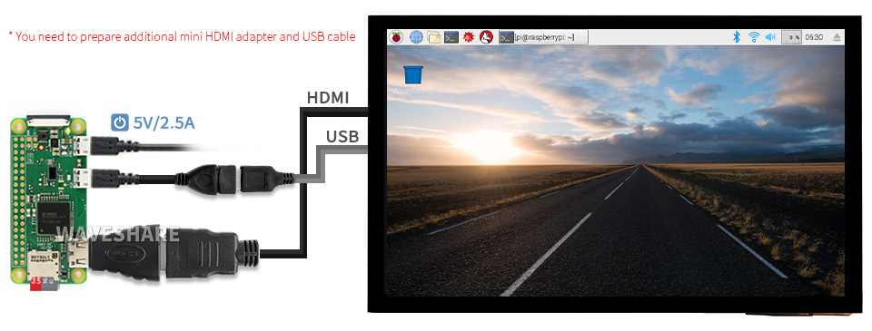
Working With Raspberry Pi Zero W
Working With AI Computer Jetson Nano
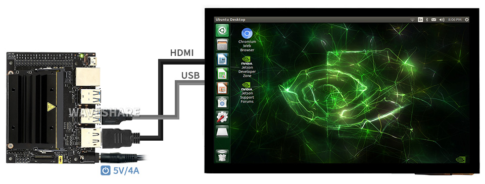
Working With Mini PC
IPS Panel

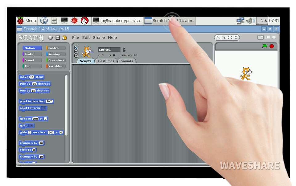
1) up to 10-points touch, depending on the operating system. 2) up to 6H hardness toughened glass panel. 3) fully laminated screen, better display experience, dust-proof.


* audio output from earphone jack and speaker header.
1 x HDMI cable
1 x HDMI to Micro HDMI Adapter
1 x USB-A to Micro-B cable
Resources

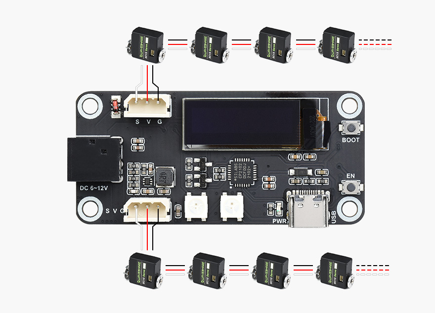
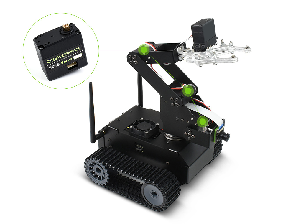
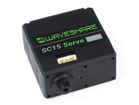
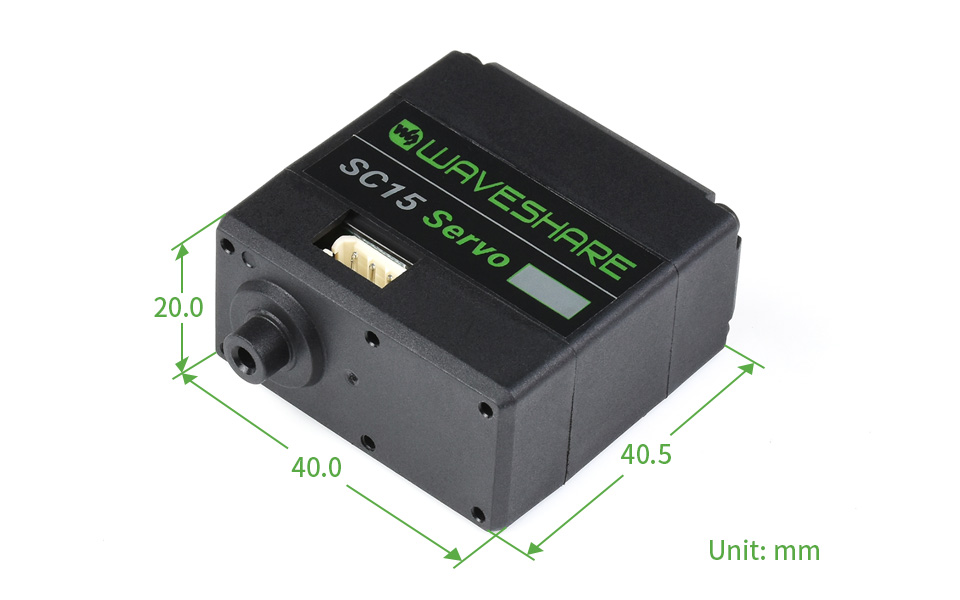
| PRODUCT TYPE | SC15 serial bus servo |
|---|---|
| TORQUE | [email protected]; 15kg.cm@6V; [email protected] |
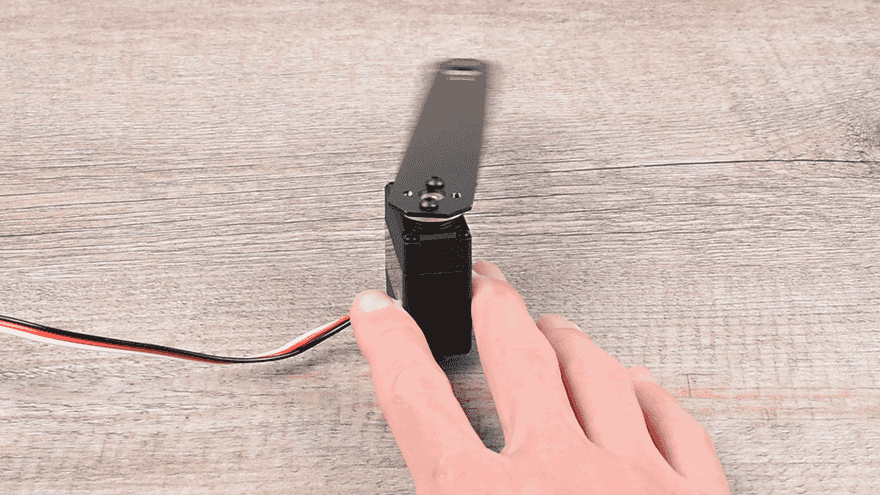
| ROTATION ANGLE | 180° (servo mode angle control) / 360° (motor mode continuous rotation) |
| POS SENSOR RESOLUTION | 180° / 1024 |
| MECHANICAL LIMITED ANGLE | No Limit |
| OPERATING VOLTAGE | 4.8-8.4V |
| GEAR | high precision metal gear |
| IDLING SPEED | 0.18sec / 60°@4.8V 0.16sec / 60°@6V |
| ID RANGE | 0-253 |
| BAUDRATE | 38400bps ~ 1Mbps |
| FEEDBACK | Position, Load, Speed, Input Voltage |
| IDLING CURRENT | 200 mA |
| STALLING CURRENT | 1700 mA |
Application Examples
- Servos will provide various feedback like position, speed, torque lock, operating mode (servo mode, servo motor mode, etc.) for advanced projects requiring closed-loop automatic control
- Ideal choice for building quadruped robots, hexapod walkers, robotic arms and other robotic projects requiring multiple servos
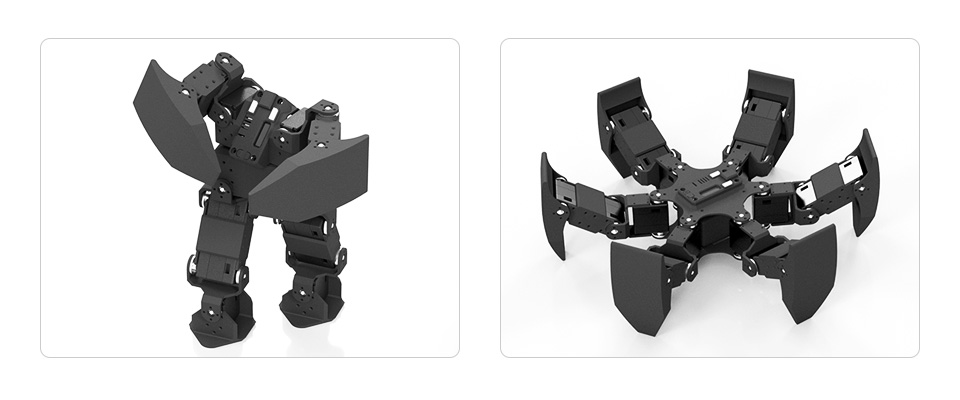
* images here are for reference ONLY
Up To 253 Servos Can Be Connected In Series At The Same Time
Up To 17kg.Cm Torque On 8.4V Voltage, Suitable For Building Quadruped Robots, Hexapod Walkers, Robotic Arms And Other Robotic Projects Requiring Multiple Servos
Two-Way Feedback
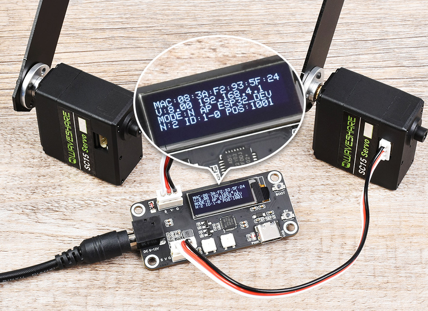
The Servos Will Provide Various Feedback Like Position, Load, Speed, And Input Voltage,
In Real Time
precise rotation angle control, on servo mode

continuous rotation, on motor mode
Nylon and fiberglass case
Improved heat-resistance, size stability, rigidity, and mechanical performance
High strength aluminum servo wheels
Using T6061 aluminum alloy, good corrosion-resistance

High precision copper and steel gears
Ingenious combination of the two, lower operating noise, better stability and mechanical performance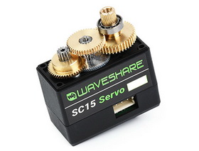
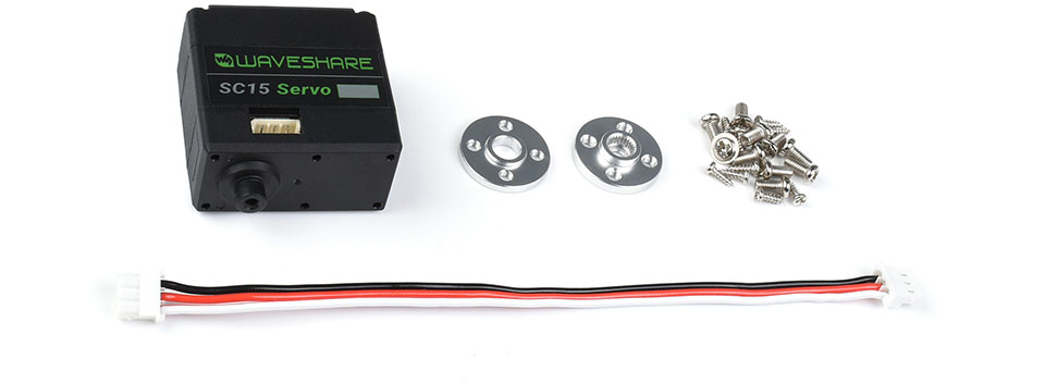
- What's in the box?

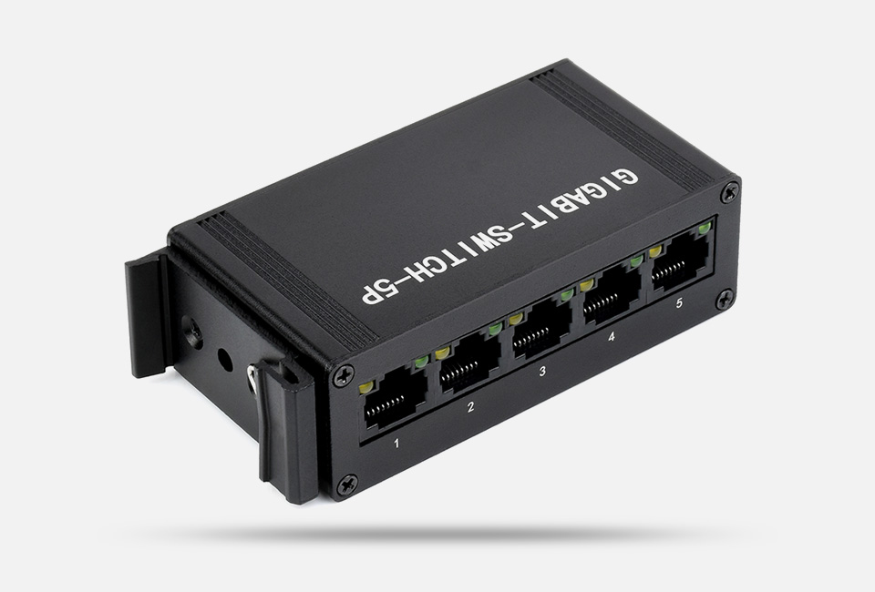
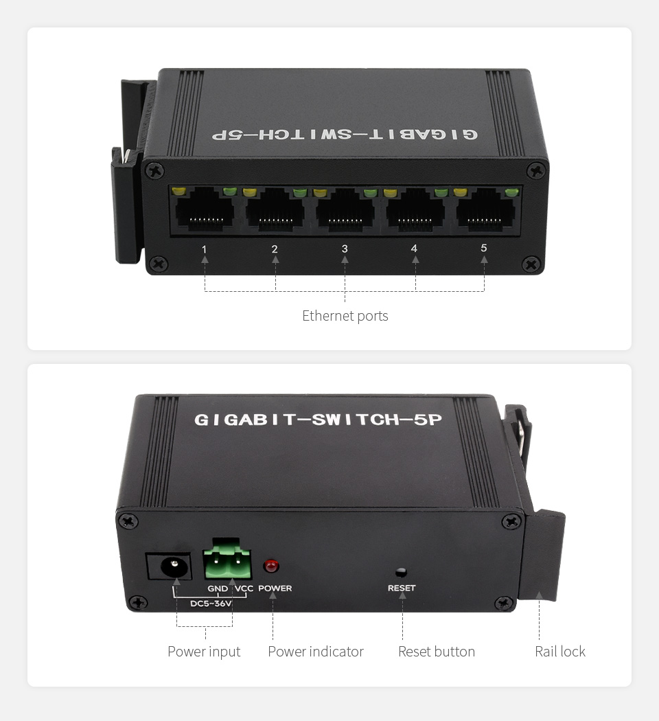
Industrial Grade 5P Gigabit Ethernet Switch, IEEE 802.3x-Compliant Full-Duplex 10/100/1000M Connection, DIN Rail Mount
Full-duplex 10/100/1000M connection
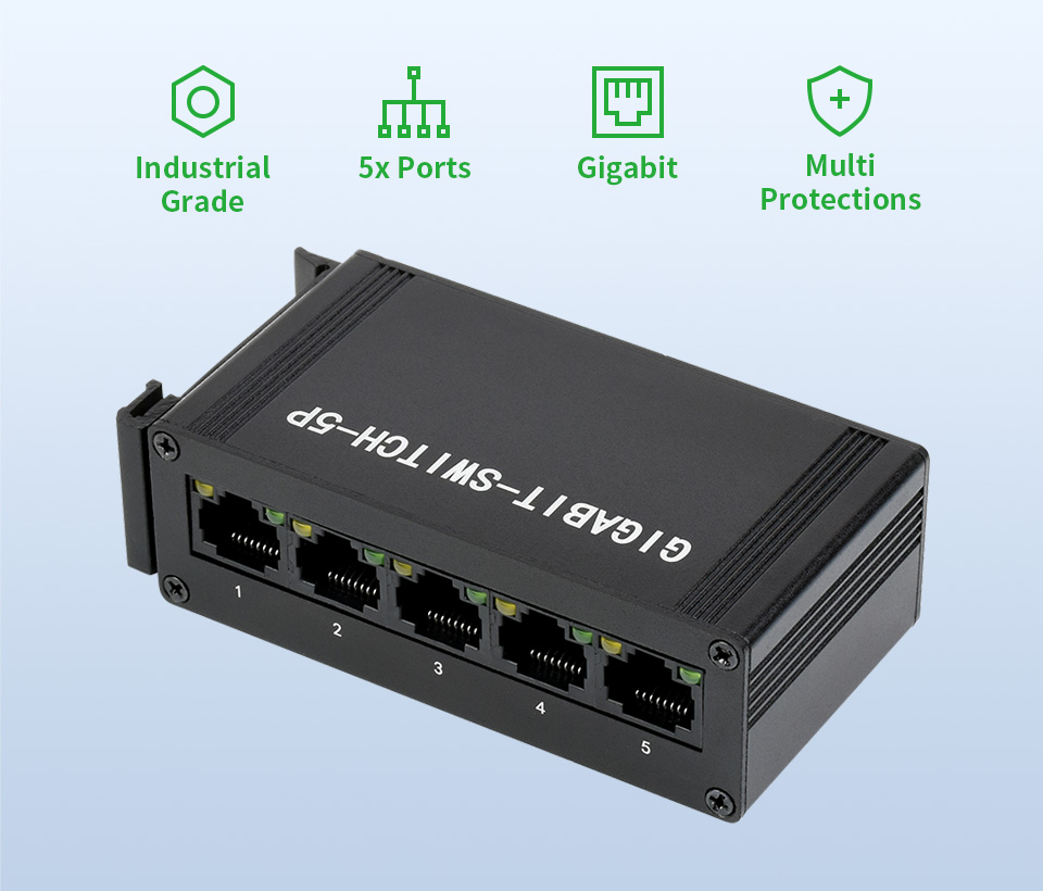
Features At A Glance
- Onboard switch chip, 5x ports 10/100/1000M non-blocking switch architecture
- Full-duplex 10/100/1000M support for each port (the half-duplex 100M connection is only supported on 10/100M mode)
- Full/Half-duplex operations with IEEE 802.3x flow control and back pressure support
- Allow forwarding 9216 bytes huge data packet on linear speed
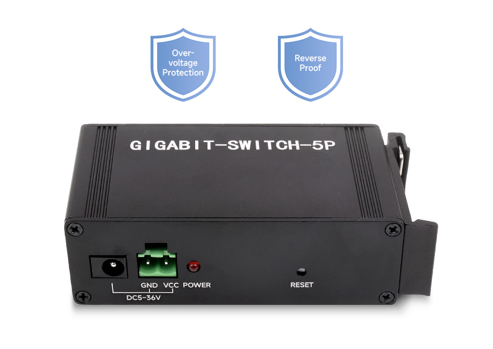
- Over-voltage protection, effectively preventing damages caused by other high voltage power supply
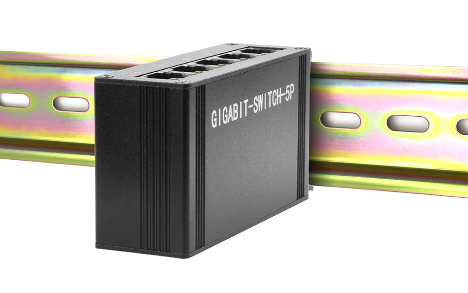
- Industrial grade alloy case, solid and durable, with DIN rail mount support for easy installing
Robust Alloy Body
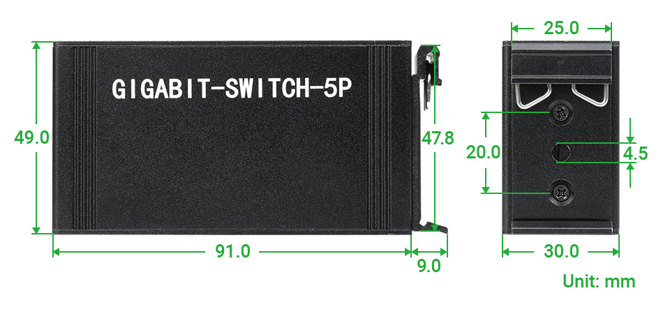
DIN Rail Mount Support
Compatible With 25mm Standard Rail
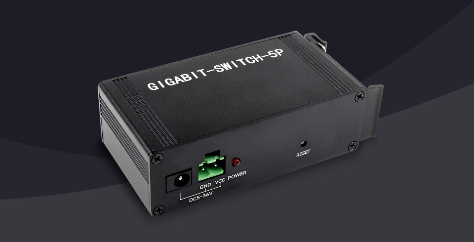
Wide Range Supply, Multiple Protections
5~36V Wide Voltage Range Power Supply, Dual Power Inputs (DC Jack And Screw Terminal)
Onboard Over-Voltage Protection And Reverse-Proof Protection
Plug & Play
5x 10/100/1000M Ethernet Ports With Auto MDI/MDI-X Support,
No Extra Configuration Required, Plug And Play
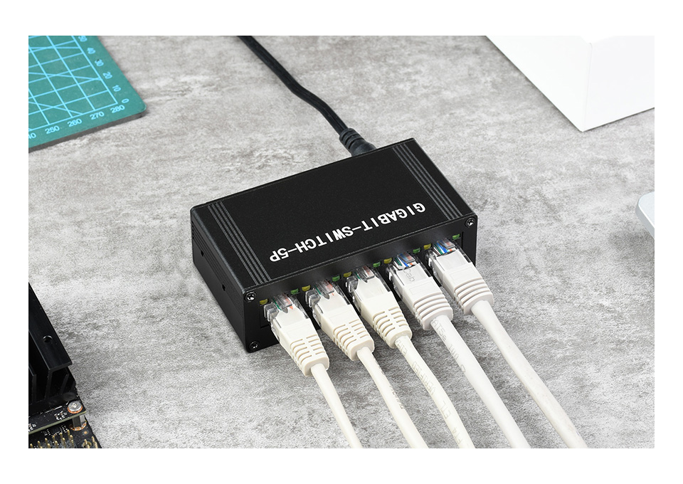
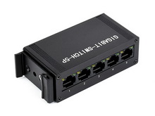
Application Examples

Interface Introduction
Outline Dimensions
- PACKAGE CONTENT
Weight: 0.211 kg
- Gigabit-Switch-5P x1
- Power supply screw terminal x1
- 12V 1A power adapter x1
 2
2 3
3Resources & Services

Features at a glance
Using pogo pin connection, the Zero 2W can be easily attached
Easily compatible with the interfaces of Raspberry Pi 3B / 3B+ boards
Onboard headphone jack(extended from USB) and an additional speaker header
Onboard 4-ch USB ports, compatible with USB 2.0 / 1.1 transmission
Onboard RTL8152B Ethernet chip, support 1-ch RJ45 Ethernet port, 10 / 100 M adaptive
Not compatible with the first generation Zero
Based on Raspberry Pi Zero 2W
Use Pi Zero 2W to reproduce the original appearance of the 3B series as much as possible
More Cost-effective Choice
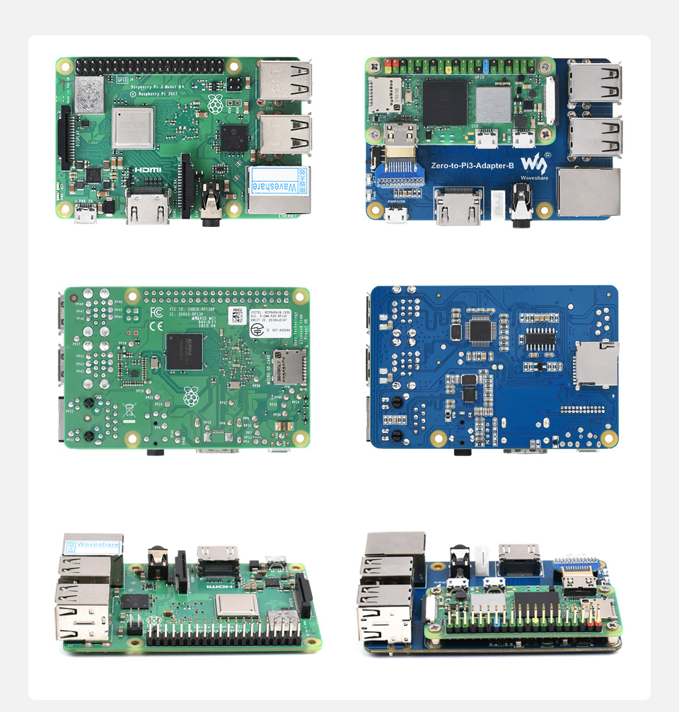
for reference only, Pi Zero 2W is NOT included
Using pogo pin connection, the Zero 2W can be easily attached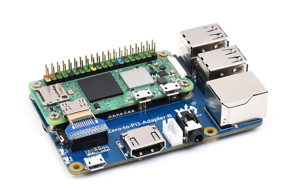
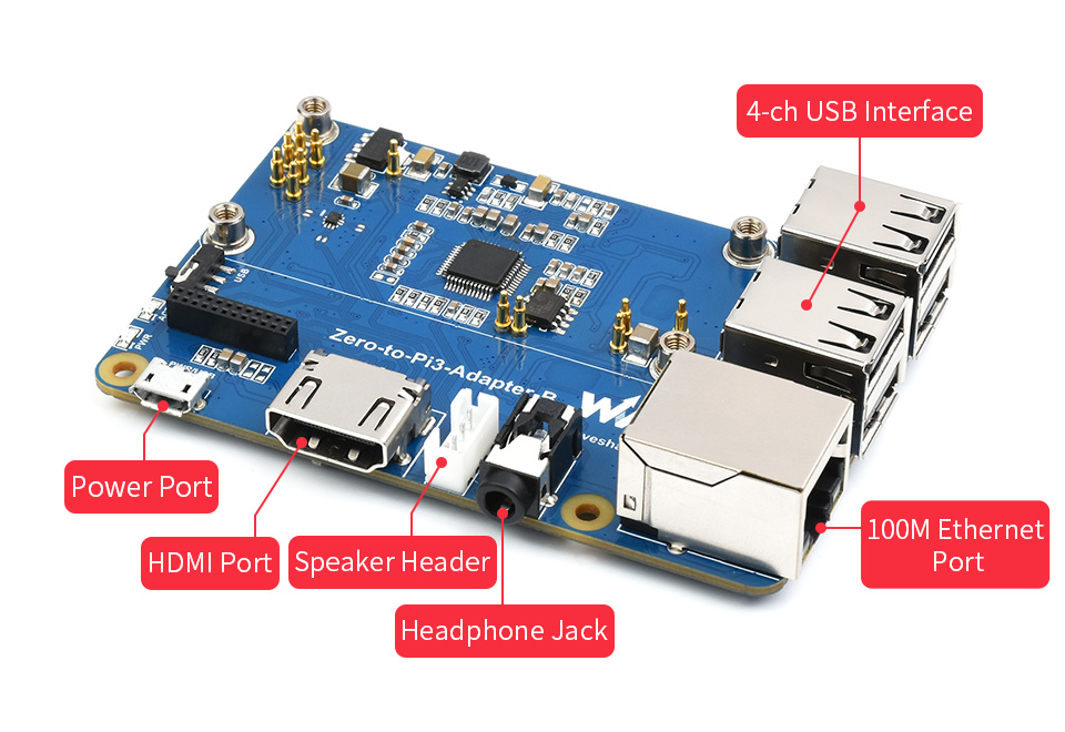
Onboard 4-ch USB Interface, 100M Ethernet Port and HDMI Port
Note: The Ethernet port does not support PoE function
Easy access to Pi 3B series HATs or other development projects
Note: the height of the GPIO is higher than the Pi 3B / 3B+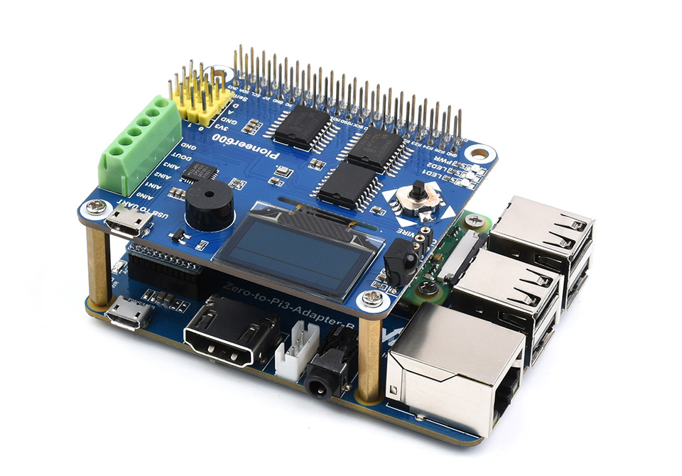
Support 3.5mm headphone jack and 4PIN speaker header
When headphone is plugged in, the speaker will be automatically disabled.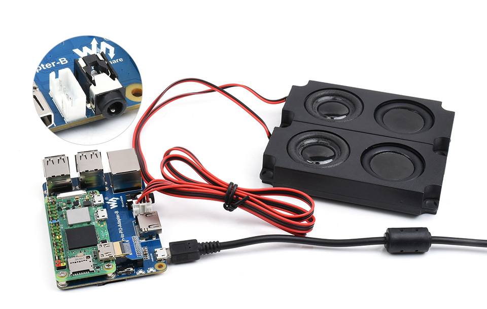
Outline dimensions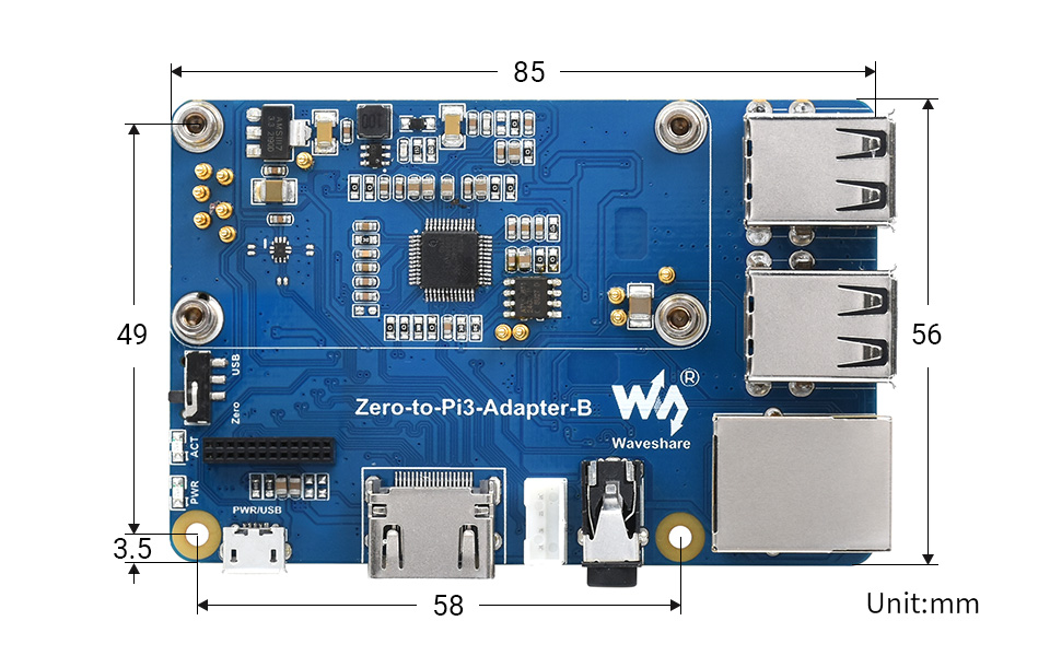
What's in the box?
1 x Zero 2W adapter board
4 x mounting screws
You will also need....
a Raspberry Pi Zero 2 W
Resources

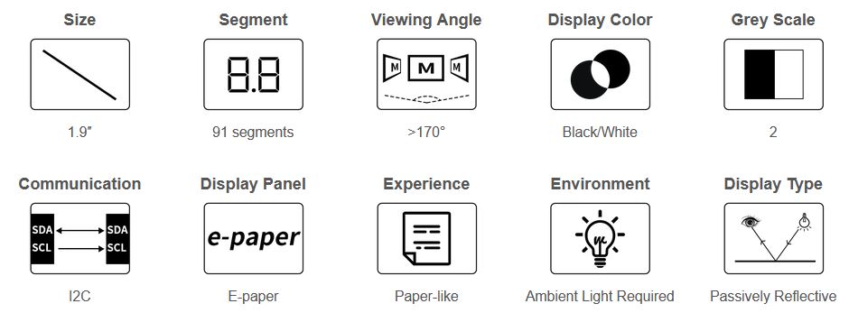
Ideal for Temperature and Humidity meter, Humidifier, Digital Meter...
- No backlight, keeps displaying last content for a long time even when power down
- Ultra low power consumption, basically power is only required for refreshing
- I2C interface, for connecting with controller boards like Raspberry Pi/Arduino/STM32, etc.
- Onboard MOS voltage translating circuit, compatible with 3.3V/5V MCUs
- Comes with development resources and manual(driver board schematic, examples for Raspberry Pi/Arduino/STM32)
| operating voltage | 3.3V/5V | grey scale | 2 |
|---|---|---|---|
| interface | I2C | Partial Refresh Time | 0.3s |
| outline dimensions | 51 × 34 mm | full refresh time | 2s |
| display size | 41.35 × 28.11 mm | refresh power | <5mW (typ.) |
| Segments | 91 | standby current | <0.01uA (almost none) |
| display color | Black/White | viewing angle | >170° |
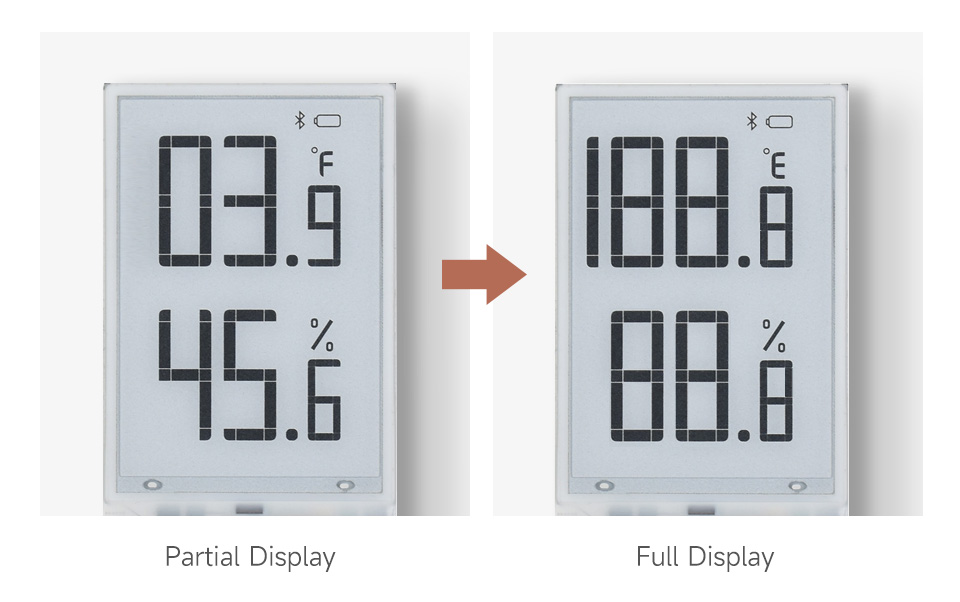
E-paper display utilizes microcapsule electrophoretic technology for displaying, the principle is: charged particles suspended in clear fluid will move to sides of microcapsule when electric field is applied, making the microcapsule become visible by reflecting ambient light, just as traditional printed paper.
E-paper display will clearly display images/texts under lamplight or natural light, requires no backlight, and features nearly up to 180° viewing angle. It is usually used as e-reader due to its paper-like effect.
For Use With Controller Boards Like Raspberry Pi/STM32/Arduino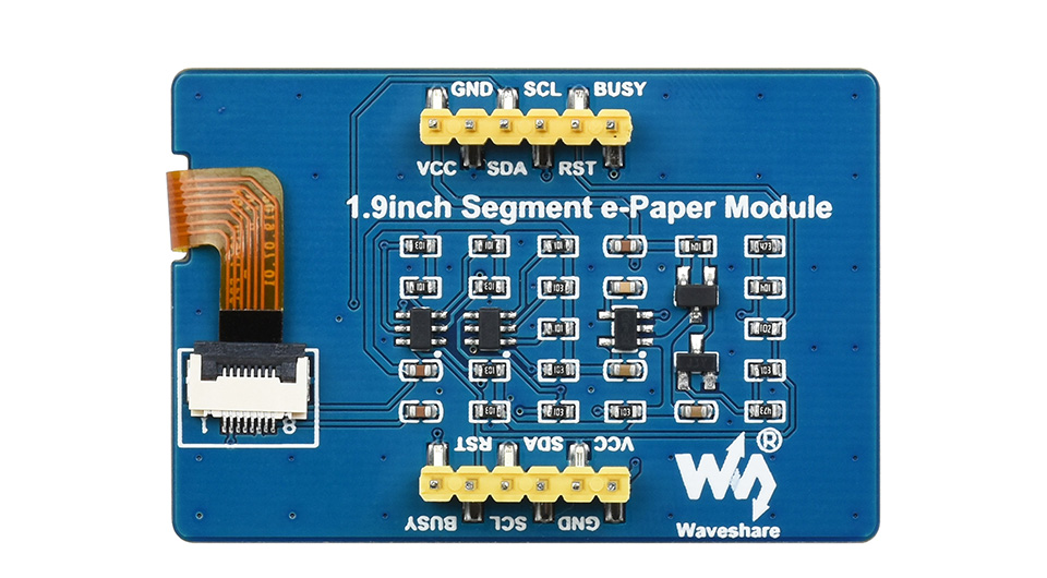
| VCC | Power (3.3V / 5V input) |
|---|---|
| GND | Ground |
| SDA | I2C data input |
| SCL | I2CI clock input |
| RST | External reset, low active |
| BUSY | Busy status output pin (high level means busy) |
Application Examples
Suitable For Temperature and Humidity meter, Humidifier, Digital Meter...
Outline dimensions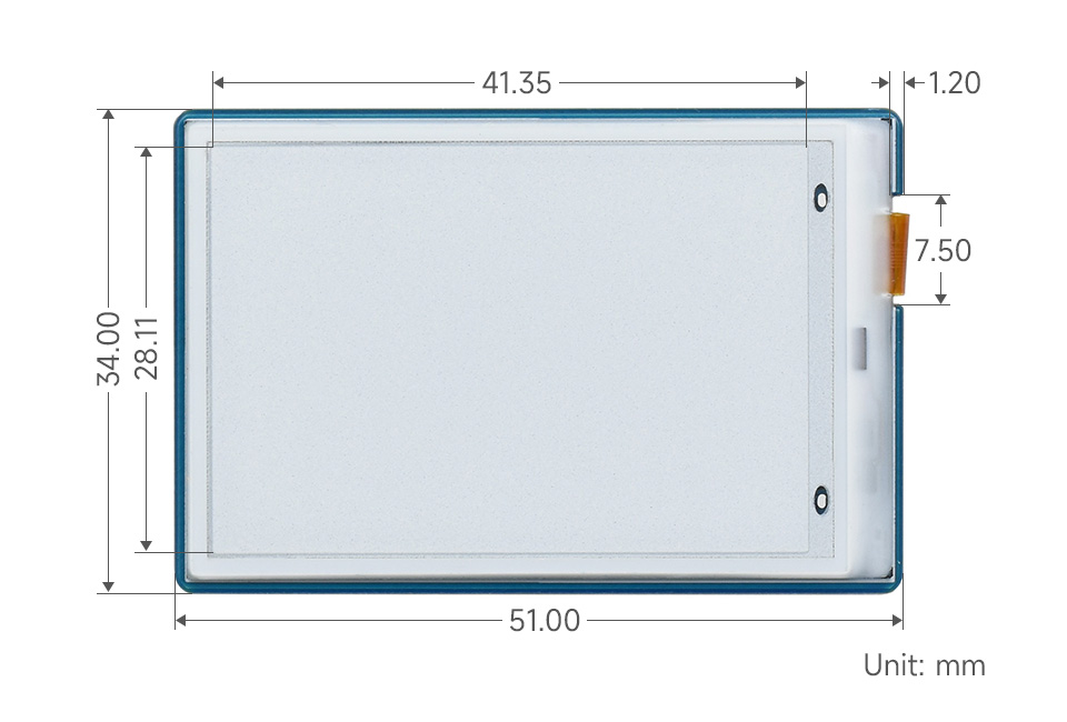
What's in the box?
1 x 1.9inch Segment e-Paper Module
1 x 6Pin Cable
Resources