Learn how to pixel paint mini works of art on your Unicorn HAT using your Pi and a web browser
Beginner / Unicorn HATDisplays
This is a great blue backlight LCD display. As the pin resources of the Arduino controller are limited, your project may not be able to use a normal LCD shield after being connected with a certain quantity of sensors or SD cards. However, with this I2C interface LCD module, you can realize data display via only 2 wires. If you already have I2C devices in your project, you can still program this LCD with the correct I2C address. It is fantastic for Arduino-based projects.
Note: If the display is not clear (or blank), try to adjust the contrast level by tuning the onboard potentiometer.
Features
- I2C Address: 0x27
- Backlight (White character on Blue background)
- Supply voltage: 5V
- Size: 82x35x18 mm
- Come with I2C interface
What's in the box?
1 x I2C 1602 Serial LCD for Arduino & RPI
Resources
- Getting Started with I2C Serial LCD and Arduino, a tutorial by Cytron Technologies
- How to Connect I2C Lcd Display to Arduino Uno, a tutorial by JunezRiyaz in Instructables
It has four digits and a decimal point on each digit, designed for numeric output, so you can use it to add a clock, timer or counter into your next project.
These displays are multiplexed, common-cathode. What that means it that you can use a 74HC595 or just 8 microcontroller pins if you can spare them to control the 8 anodes (7-seg decimal) at about ~15mA each, and then connect NPN transistors or a TPIC6B595 to the cathodes to sink the 8*20mA = ~120mA maximum per digit.
This is an ultra bright RED colour.
Specifications
- 100mcd
- 14.2mm (0.56") digit height
- Color: red (630nm)
- Common cathode display
- Maximum power dissipation per segment: 66mW
- Maximum pulse peak forward current per segment (1/10th duty cycle, 0.1ms pulse width): 100mA
- Maximum forward current per segment: 20mA
- Maximum reverse voltage: 5V
- Maximum reverse current: 20µA
- Typical forward voltage: 2.1V at 20mA
- Maximum forward voltage: 2.5V at 20mA
- Operating temperature range: -30°C - 70°C
- Typical luminous intensity: 20mcd
What's in the box?
1 x Four Digit Seven Segment Display Red
Resources
Specifications
- A single module can drive a 8x8 dot matrix common cathode
- Working voltage: 5V
- Module size: 12.8 x 3.2 x 1.3 cm (L*W*H)
- With 64 fixing screw holes, hole diameter: 3mm
- Module with input and output interfaces, support for cascading multiple modules
What's in the box?
1 x MAX7219 Dot Matrix Module
1 x 5pin jumper Cable
Resources
Wiring
1. The left side of the module is the input port, and the right is the output port.
2. Control of a single module, the input port only need to receive CPU.
3. The more a module cascade and input end of the first module is connected with the CPU and input end of the input end of the output end is connected to the second module, output terminal of the second module connected with the three modules, and so on.
For example: 51 SCM
VCC→5V
GND→GND
DIN→P2.2
CS →P2.1
CLK→P2.0


https://max7219.readthedocs.io/en/0.2.3/
Clock example
Python Library
Basic 1 digit seven segment display can show numbers from 0-9 and a few characters. Consisting of seven LEDs (hence its name) arranged in a rectangular fashion. Each of the seven LEDs is called a segment because when illuminated the segment forms part of a numerical digit to be displayed.
Features:
Model: 5611BH Common Anode
Size: 0.56 inch
Color: red
Package includes:
1 x Red 7 Segment 0.56 Inch 1 Bit Common Anode LED Digital Tube
Some code examples
https://circuitdigest.com/microcontroller-projects/raspberry-pi-7-segment-display-tutorial
https://raspi.tv/2015/how-to-drive-a-7-segment-display-directly-on-raspberry-pi-in-python
What's going to protect your beloved Raspberry Pi from an onslaught of rainbow-coloured fusion? That's right, it's Unicorn HAT.
Sporting a matrix of 64 (8 x 8) RGB LEDs and powered directly from the Pi, this is the most compact pocket aurora available.
Unicorn HAT provides a wash of controllable colour that is ideal for mood-lighting, 8x8 pixel art, persistence of vision effects, status indications, or just blasting colour into your surroundings.
The MagPi said that Unicorn HAT was "one of the coolest HATs around"
Features
- 64 RGB LEDs (WS2812B)
- LED data driven via DMA over PWM
- Unicorn HAT pinout
- Compatible with Raspberry Pi 3, 2, B , A , Zero, and Zero W
- Python library
- Comes fully assembled
Software
We've put together a Unicorn HAT Python library to make it a breeze to use, including lots of beautiful examples of what it can do.
Notes
- Warning: WS2812 LEDs are bright enough to cause eye pain, do not look at them directly when brightly lit. We recommend the use of a diffuser.
- Photo-sensitivity warning: flashing, strobing, and patterns of lights may cause epileptic seizures. Always take care and immediately stop using if you feel unwell (dizziness, nausea, affected vision, eye twitching, disorientation).
- Power: Unicorn HAT requires a >2A microUSB power supply for your Pi. We recommend the official Raspberry Pi power supply.
- Compatibility (audio): as Unicorn HAT uses PWM and GPIO18, it will interfere with analogue audio playback (random colour patterns and flickering). HDMI should work just fine!
Short video on the Unicorn HAT
Getting Started with Unicorn Paint Make rainbows with Unicorn HAT Learn how to use Unicorn HAT and HSV colour to make awesome rainbows
Intermediate / Unicorn HATGetting Started with Unicorn HAT Learn how to use Unicorn HAT, the vibrant 8x8 pixel colour display for your Pi
Beginner / Unicorn HATUsing Unicorn HAT in IDLE Learn how to use Unicorn HAT in IDLE, the Python IDE
Beginner / Unicorn HAT
This RGB LED HAT can be easily attached on top of the Raspberry Pi to display colorful effect, and controlled by only one signal pin.
Features- Supports any revision of Raspberry Pi (directly plugable)
- Onboard 4 × 8 RGB LED (WS2812B)
- Control pin is configurable via jumpers (0Ω resistor)
- Break out control pins, easy for working with other MCUs
- Comes with development resources and manual (examples in Python and Web control)
- Operating voltage: 5V
- Brightness: adjustable 256 levels
- Color depth: 24-bit true color (8-bit for R/G/B respectively, totally 256x256x256=16777216 colors)
- Data rate: 800Kbps(typ)
- Dimension: 65mm × 30.2mm
- Mounting hole size: 3.0mm
How to Use
In the case of working with a MCU:
- 5V ↔ 5V power
- GND ↔ GND
- DIN ↔ Signal input
- DOUT ↔ Signal output (optional)
Development Resources
Specifications
- A single module can drive a 8x8 dot matrix common cathode
- Working voltage: 5V
- Module size: 12.8 x 3.2 x 1.3 cm (L*W*H)
- With 64 fixing screw holes, hole diameter: 3mm
- Module with input and output interfaces, support for cascading multiple modules
What's in the box?
1 x MAX7219 Dot Matrix Module
1 x 5pin jumper Cable
Resources
Wiring
1. The left side of the module is the input port, and the right is the output port.
2. Control of a single module, the input port only need to receive CPU.
3. The more a module cascade and input end of the first module is connected with the CPU and input end of the input end of the output end is connected to the second module, output terminal of the second module connected with the three modules, and so on.
For example: 51 SCM
VCC→5V
GND→GND
DIN→P2.2
CS →P2.1
CLK→P2.0


https://max7219.readthedocs.io/en/0.2.3/
Clock example
Python Library
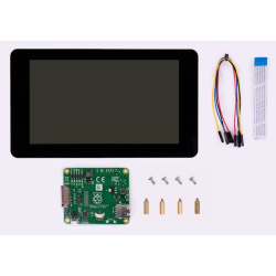
- 1024×600 high resolution
- Resistive touch control
- Compatible and Direct-connect with any revision of Raspberry Pi (except the Pi 1 model B or Pi Zero, which requires an HDMI cable)
- Drivers provided (works with your own Raspbian/Ubuntu directly)
- Also works as a computer monitor, in this case, touch panel is unavailable and HDMI cable is required
- HDMI interface for displaying, no I/Os required (however, the touch panel still needs I/Os)
- Backlight can be turned off to lower power consumption
Interface
PIN NO. | SYMBOL | DESCRIPTION |
---|---|---|
1, 17 | 3.3V | Power positive (3.3V power input) |
2, 4 | 5V | Power positive (5V power input) |
3, 5, 7, 8, 10, 11, 12, 13, 15, 16, 18, 24 | NC | NC |
6, 9, 14, 20, 25 | GND | Ground |
19 | TP_SI | SPI data input of Touch Panel |
21 | TP_SO | SPI data output of Touch Panel |
22 | TP_IRQ | Touch Panel interrupt, low level while the Touch Panel detects touching |
23 | TP_SCK | SPI clock of Touch Panel |
26 | TP_CS | Touch Panel chip selection, low active |
External Dimensions

What's in the box?
1 x 10.1inch Resistive Touch Screen
Resources
Features
- 13.3inch IPS screen,1920x1080 high resolution
- Toughened glass capacitive touch panel, 6H hardness
- Supports popular mini PCs such as Raspberry Pi, BB Black, as well as general desktop computers
- When works with Raspberry Pi, supports Raspbian, Ubuntu, WIN10 IOT, single touch, and driver free
- When work as a computer monitor, supports Windows 10/8.1/8/7, ten-points touch, and driver free
- Multi languages OSD menu, for power management, brightness/contrast adjustment, etc.
- 3.5mm audio jack, supports HDMI audio output
- Embedded ferrite Hi-Fi speaker
- Also supports VGA input (specific cable is required and should be purchased separately)
- 75x75mm spacing mounting holes (M4 screw hole) for general wall mount
- Comes with 75° tilt angle stand
External Dimension

What's in the box?
1 x 13.3inch Capacitive Touch HDMI LCD
Resources
Wiki : www.waveshare.com/wiki/13.3inch_HDMI_LCD_(H)_(with_case)
The HT16K33 is a memory mapping and multi-function LED controller driver. The max. Display segment numbers in the device is 128 patterns (16 segments and 8 commons) with a 13*3 (MAX.) matrix key scan circuit. The software configuration features of the HT16K33 makes it suitable for multiple LED applications including LED modules and display subsystems. The HT16K33 is compatible with most microcontrollers and communicates via a two-line bidirectional I2C-bus.
Features:
Operating voltage: 4.5V~5.5V.
Integrated RC oscillator.
I2C-bus interface.
16*8 bits RAM for display data storage.
Max. 16 x 8 patterns, 16 segments and 8 commons.
R/W address auto increment.
Max. 13 x 3 matrix key scanning.
16-step dimming circuit.
Selection of 20/24/28-pin SOP package types.
Applications:
Industrial control indicators.
Digital clocks, thermometers, counters, multi meters.
Combo sets.
VCR sets.
Instrumentation readouts.
Other consumer applications.
LED Displays.
Package included:
1 x Module
Getting Started
Use Four Letter pHAT to display... four letter words. Not that sort!
Pi ZERO and case not included!
Four Letter pHAT has four 14-segment displays that you can use to display text, numbers, and a host of other characters. Its LEDs are a beautiful retro green, just like you old digital alarm clock. They're driven by the HT16K33 chip over I2C.
It's perfect as a readout for your projects, displaying temperatures, times, etc. and becomes really useful when combined with some of our other boards like Enviro pHAT or Explorer pHAT to display their sensor values.
Features
- Four 14-segment displays with green LEDs
- HT16K33 driver chip
- Compatible with Raspberry Pi 3, 2, B , A , Zero, Zero W
- Python library
- Female header and display pins require soldering
Software
Our handy one-line installer will install the Four Letter pHAT Python library for you. We've included a bunch of examples too, to show off what you can do with Four Letter pHAT; things like a clock, a countdown timer, or CPU activity monitor.
LCD module 3.5 inch TFT LCD screen 3.5 " for Arduino UNO R3 Board and support mega 2560 R3

Watch a video on this item at https://www.youtube.com/watch?v=PAPW97X6IRM

What's in the box?
Resources:
We have found the best Libary to use to run this display is: MCUFRIEND_kbv Library for Uno 2.4, 2.8, 3.5, 3.6, 3.95 inch mcufriend Shields
You can find out more: https://github.com/prenticedavid/MCUFRIEND_kbv
Open Arduino IDE
Click on Sketch -> Include library -> Manage Libraries -> and search for MCUFRIEND
Once installed, you can test your display using the provided examples
Is this not the cutest little display for the Raspberry Pi? It features a 2.8" display with 320x240 16-bit color pixels and a capacitive touch overlay. That's right, instead of a resistive touchscreen, which requires a fingernail or stylus, you can now use a fingerpad.
The screen looks much nicer, with a black bezel and glass overlay.
This updated design fits perfectly onto the Pi Zero, Pi 3, Pi 2 or Model A , B ! (Any Pi with a 2x20 connector) Not for use with an old Pi 1 with 2x13 connector. This version also has all 40 pins GPIO pins brought out so you can connect a 40-pin GPIO cable underneath.
The display and touchscreen uses the hardware I2C Pins (SDA & SCL), SPI pins (SCK, MOSI, MISO, CE0) as well as GPIO #25 and #24. All other GPIO are unused and you can still share the I2C pins with sensors, LED drivers, etc. Since we had a tiny bit of space, there's 4 slim tactile switches wired to four GPIOs, that you can use if you want to make a basic user interface. For example, you can use one as a power on/off button.
Use it for console access or easily pop up X11 onto the PiTFT for a mini monitor, although its rather small at 320x240. Instead, we recommend using PyGame or other SDL-drawing programs to write onto the frame buffer.
Raspberry Pi computer and enclosure not included! As of July 22nd, 2015 this display comes fully assembled with tactile switches too
TECHNICAL DETAILS
- Screen Dimensions: 50mm x 69mm x 4mm / 2" x 2.7" x 0.16"
- PCB Dimensions: 56mm x 85mm x 11mm / 2.2" x 3.3" x 0.4"
- Weight: 47g
Datasheets, EagleCAD PCB files, Fritzing object and more in the tutorial!
This is a colorful display module designed for the BBC micro:bit, 1.8inch diagonal, 160x128 pixels, capable of displaying 65K colors.
Tired of the 5x5 LED matrix? Time to get a tiny monitor for your micro:bit, this one would be the ideal choice.
- micro:bit edge connector, directly pluggable
- Embedded driver ST7735S, supports 65K colors
- Onboard SRAM 23LC1024, used as display cache, no more out of memory
- SPI interface, takes up only a few IO pins
- Backlight adjustment via PWM
- Reserved solder pads for control interface, make it easy to connect with Arduino/Nucleo boards
- Comes with development resources (micro:bit graphical demo/user manual, etc.)
Specifications
- Driver: ST7735S
- Resolution: 160x128
- Display color: RGB, 65K colors
- Operating voltage: 3.3V
- Dimension: 61mm x 51.5mm
Pinouts
PIN | micro:bit PIN | DESCRIPTION |
---|---|---|
3V3 | 3V3 | Power |
GND | GND | Ground |
MISO | P14 | SPI data master input/slave output |
MOSI | P15 | SPI data master output/slave input |
SCK | P13 | SPI clock input |
LCD_CS | P16 | LCD chip selection |
RAM_CS | P2 | SRAM chip selection |
DC | P12 | LCD data/command |
RST | P8 | LCD reset |
BL | P1 | LCD backlight |
Dimensions

What's in the box?
1 x 1.8inch LCD for micro:bit
Resources
- This is a basic 16 character by 2 line display.
- Utilizes the extremely common HD44780 parallel interface chipset.
- Interface code is freely available.
- Blue Backlight with white words.
- uses 4 Bit Arduino LCD Library.
- Size:8cm x 5.9cm - 3.15inch x 2.32inch
What's in the box?
1 X Keypad Shield 1602 LCD
Resources
DFRobot WIKI

Specifications
- 2004 204 20X4 Character LCD Display Module Blue Backlight.
- Blue backlight
- Fully assembled and tested Serial LCD 20x4 Module
- Display Format: 20 Characters x 4 lines
- Supply voltage: 5V
- The module can be easily interfaced with a MCU
- The module is a low-power consumption character LCD Module with a built-in controller
- Size: approx. 98mm x 60mm x 12mm

What's in the box?
1 x 2004 LCD Display Module
Resources
Interfacing with a 2004 and 1602 LCD

5 inch Resistive Touch Screen LCD, HDMI interface, Designed for Raspberry Pi. Mid-sized Raspberry Pi or SBC 5 Inch Touch LCD with HDMI interface! Especially useful for those smaller embedded projects, such as adding LCD control to CNCs or 3D printers.
Specifications
The LCD
- 800×480 high resolution, touch control
- Compatible and Direct-connect with any revision of Raspberry Pi (except the Pi 1 model B or Pi Zero, which requires an HDMI cable)
- Drivers provided (works with your own Raspbian/Ubuntu directly)
- HDMI interface for displaying, no I/Os required (however, the touch panel still needs I/Os)
- Backlight can be turned off to lower power consumption
- High quality immersion gold surface plating
The Case
- Material : high quality bicolor Acrylic, black and white
- Comes with bottom holder, optional tilt angle, 45° or 60°
- Features mounting holes for Raspberry Pi A /B /2B/3B
What's in the box?
1 x HDMI connector
1 x Touch pen
1 x RPi screws pack (4pcs)
1 x Bicolor Case for 5inch LCD
1 x Screws Pack
Resources
How to install: instructions
Wiki : www.waveshare.com/wiki/5inch_HDMI_LCD

- 480x320 hardware resolution
- Resistive touch control
- Supports any revision of Raspberry Pi (directly-pluggable)
- 125MHz High-Speed SPI signal transmission, clear & stable display effect
- Drivers provided (works with your own Raspbian/Ubuntu/Kali/Retropie)
- Supports FBCP software driver as well, allows to config software resolution and set up dual-display
- Size perfectly fits the Pi (Raspberry Pi B /2B/3B/3B )
- High quality immersion gold surface plating
- Combined with the Raspberry Pi (refresh rate up to 50Hz), allows you to:
- Watch videos (multi formats like MP4)
- Play video games (RetroPie, take a bite)
- Take photos by touching (up to 17 camera modes)
- Use software keyboard (system interaction without keyboard/mouse)
Key Parameters
LCD Type | TFT |
---|---|
LCD Interface | SPI |
Touch Screen Type | Resistive |
Touch Screen Controller | XPT2046 |
Colors | 65536 |
Backlight | LED |
Resolution | 480x320 (Pixel) |
Aspect Ratio | 8:5 |
Power Consumption | TBD |
Backlight Current | TBD |
Operating Temp. (℃) | TBD |
PIN NO. | SYMBOL | DESCRIPTION |
---|---|---|
1, 17 | 3.3V | Power positive (3.3V power input) |
2, 4 | 5V | Power positive (5V power input) |
3, 5, 7, 8, 10, 12, 13, 15, 16 | NC | NC |
6, 9, 14, 20, 25 | GND | Ground |
11 | TP_IRQ | Touch Panel interrupt, low level while the Touch Panel detects touching |
18 | LCD_RS | Instruction/Data Register selection |
19 | LCD_SI / TP_SI | SPI data input of LCD/Touch Panel |
21 | TP_SO | SPI data output of Touch Panel |
22 | RST | Reset |
23 | LCD_SCK / TP_SCK | SPI clock of LCD/Touch Panel |
24 | LCD_CS | LCD chip selection, low active |
26 | TP_CS | Touch Panel chip selection, low active |
External Dimensions

What's in the box?
1 x 3.5inch RPi LCD
Resources
LCD control panel for 3D printers. LCD control panel through which you can achieve spooling as the 3D model Gcode files are copied to the SD card and then print the file via the LCD control panel. This version is an upgraded version of the reprap smart controller.

Features:
Using a large screen 12864LCD
With a SD card base on back, put your sliced file onto the SD card and select the file on the LCD. It can then can be printed
Product comes encoder to select the desired file
Plug and play on the RAMPS, but may need to modify the firmware to support
Specifications:
Screen size: 128x64
Cable Length (cm): 30
Input Supply Voltage: (VDC) 5
Length (mm): 93
Width (mm): 87


Package Includes:
1x LCD 12864 Smart Controller
1x Smart Adapter
2x 30cm FC Cable