Robotics
Build a BalanceBot with the Raspberry Pi!
The BalanceBot extension kit takes your GoPiGo3 and turns it into an upright balancing robot! Kit includes an IMU sensor, IR receiver, IR remote control and a set of 3 sensor mounts. Program examples provided in Raspbian for Robots in Python.
Please Note. The GoPiGo3, Raspberry Pi and other associated hardware are NOT included in this purchase.
What’s included:
- BalanceBot Power Cable (longer than the original one that comes with the GoPiGo3 base kit)
- IMU Sensor
- Infrared Reciever Sensor
- Infrared Remote Control
- Sensor Mounts (s/3)
What else do I need:
- Raspberry Pi (B or 3 recommended)
- GoPiGo3 Base Kit (Does not work with GoPiGo2 or GoPiGo1)
- 8 x AA Batteries
- Raspbian for Robots SD card (will not work with DexterOS)
NOTE: This expansion kit will not work with the GoPiGo2.
Features
- 2 wheels + motors mobile robot chasis
- Comes with all accessories to make a mobile robot
- Include 4xAA batteries holder
- Chassis size: ~215mm x ~150mm
- Wheel Diameter: 67mm
- Castor Height: 34mm
Motor parameters
- Comes presoldered with Red and Black wire, length ~ 15cm
- Bidirectional
- Gear Ratio = 48:1
- Speed with 66mm diameter wheel = 0.65 m/s at 7.2VDC
- Recommended operating voltage: 5 - 10VDC
- Noise level < 65dB
Current Consumption
- 100mA each motor at 3V
- 100mA each motor at 5V
- 120mA each motor at 6V
What's in the box?
2 x DC gear motor(TT motor) + Mini Wheel
1 x Castor wheel
1 x 4 X AA battery holder
1 x Rocker switch
2 x Black slotted disc
1 x Mounting screws and accessories
Specifications
Quantity | 1 Piece(s)/pack |
Colour | Yellow black |
Material | ABS iron |
Compatible Models | Robot, gun toy, four wheel drive toy, aircraft toy, vibration products |
Other Features | Motor speed: 100 per minutes; Torque: 4.5kg. cm1; Voltage: 3~6V; Non-loaded revolving speed: 100RPM; Non-loaded current: 60mA; Torque (6V): 4500mg cm |
What's in the box?
1 x motor
1 x wheel
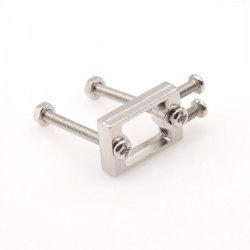
Now, we are happy to say that the pain is over, this is the bracket designed for that DC geared motor, and it is super strong and rigid as it is aluminum.
- Material: Rigid Aluminum Alloy
- Length: 22mm
- Width: 12mm
- Thickness: 5mm
- Dimension:
What's in the box?
1 x mounting bracket
4 x screws
2 x nuts
You will also need...
TT DC Gear motor
Specifications
- Product: SG90 Servo
- Torque: 2.0kg/cm(4.8V), 2.2kg/cm(6V)
- Speed: 0.09s/60°(4.8V), 0.08s/60°(6V)
- Rotate angle: 180°
- Operating voltage: 4.8 ~ 6V
- Gear: plastic
- Dead band: 7us
- Weight: 10.5g
- Dimension: 22.8mm × 12.2mm × 28.5mm
What's in the box?
1 x servo motor
Resources
ExplainingComputers has a great video on using this servo https://www.youtube.com/watch?v=xHDT4CwjUQE&t=389s
The 28BYJ-48 motor runs in full step mode, each step corresponds to a rotation of 11.25°. That means there are 32 steps per revolution (360°/11.25° = 32). In addition, the motor has a 1/64 reduction gear set.
The power consumption of the motor is around 240mA.
The ULN2003 is one of the most common motor driver ICs, consisting of an array of 7 Darlington transistor pairs, each pair is capable of driving loads of up to 500mA and 50V. Four out of seven pairs are used on this board.
The board has four LEDs that show activity on the four control input lines (to indicate stepping state). They provide a nice visual when stepping.
The board also comes with an ON/OFF jumper to isolate power to the stepper Motor.
Specifications
- High quality stepper motor with ULN2003 driver
- Suitable for microcontroller development
- Voltage: DC 5V
- Diameter: 28mm
- Step Angle: 5.625 x 1/64
- Reduction Ratio: 1/64
- Dimensions: 1.38 in x 1.18 in x 0.39 in (3.5 cm x 3.0 cm x 1.0 cm)
- Weight: 1.45 oz (41 g)
What's in the box?
1 x stepper motor
1 x ULN2003 driver
Resources
How to control a ULN2003 stepper motor with Raspberry Pi

LM393 comparing two photosensitive resistance, when the imbalance (eg side pressure runway black) immediately control side of the motor stops rotating, the other side of the motor rotation acceleration, so that the car modification direction, return to the right direction, the whole process is a closed loop therefore rapid and sensitive control.
With the aim of simplifying the complex principle, we first have a by digital circuit to the intelligent tracking car, in the assembly process, we could not only familiar with the mechanical principle gradually can learn to: photocell, a voltage comparator, a motor drive circuit, and other related electronic knowledge.
Photosensitive resistance device:
This is light-sensitive resistance, it can detect the external light intensity, the stronger the outside light photosensitive resistance resistance is small, the outside light weaker resistance is greater when the red LED light projected on a white and black runway because reflection rate is different, the resistance value of the light-sensitive resistance will occur obvious difference for subsequent circuit control.
LM393 comparator integrated circuit:
LM393 is a dual voltage comparator integrated circuit, which consists of two independent precision voltage comparator. its role compare the two input voltage, based on the level of two input voltage change the level of output voltage. The output has two states: close to open or close to the low level, LM393 using open collector output, so it is necessary to add the pull resistance to output high level.
DC motor with gear reduction:
DC motor drive the car needs to slow down, otherwise to speed up the car, then ran too fast not control, and the deceleration torque is too small and could not run up. We specialize in custom of this type of motor is integrated with the reduction gear and greatly reducing the manufacture difficulty is very suitable for our use.
LM393 comparing two photosensitive resistance, when the imbalance (eg side pressure runway black) immediately control side of the motor stops rotating, the other side of the motor rotation acceleration, so that the car modification direction, return to the right direction, the whole process is a closed loop therefore rapid and sensitive control.
Assembly steps:
The first step: circuit part of the basic welding
The welding circuit part is relatively simple, the welding sequence according to the element height from low to high, the first 8 resistance welding, welding must use a multimeter to confirm whether the proper welding resistance, polar components such as transistors, green lights, definitely clear electrolytic capacitor polarity as reference element we are photo welding, welding capacitor short is the negative side of the insertion pin PCB screen printing shadow, green welding LED note long pin is positive, and the welding is not too long or easy bad welding, D4 D5 R13 R14 can temporarily do not weld, the integrated circuit chip can be inserted, preliminary after completion of welding check carefully prevent, be negligent.
Second step: mechanical assembly
The universal wheel screw is inserted into the PCB hole, and screwed into the universal wheel nut and a universal wheel. the battery box is stuck on the PCB by the double adhesive tape, the lead wire passes the PCB reserved Kong Han received PCB, the red line is connected with the 3 V positive power supply, and the yellow line is connected to the ground.
Mechanical part and assembly can be mounted first wheels, wheel consists of three pieces of black acrylic round tablets, assembly prior to exposing protective film, the inside of the wheel center hole grows circular hole, middle of the round plate diameter is relatively small, lateral wheel piece center hole Shiyuan, with two screw nuts fixed set good three round tablets, and black self-tapping screws fixed on the rotating shaft of the engine. Finally the silicone rubber tire sleeve on the wheel. Lead connection lead wire of the motor and the wheel assembly is the use of the glue on the PCB making position, attention wheels and the PCB edge retaining sufficient clearance, the motor leads are soldered to the PCB. Note that adequately longer lead, to avoid the motor rotation direction error is convenient for changing the lead wire of the order.
The third step: the installation of opto-electronic circuits
Photosensitive resistance and light-emitting diode (attention polarity) is the reverse installed on the PCB, and the ground distance of about 5mm, the distance between the light-sensitive resistance and light-emitting diode is also about 5mm. Finally can pass electrical test.
The fourth step: Vehicle debugging
In the battery box in 2 AA batteries, switches to dial in the "on", the car driving right reverse is traveling along the direction of the universal wheel, if hold the left side of the photosensitive resistance, the car to the right of the wheel rotation, Keep to the right of photosensitive resistance, the left side of the car wheel must turn, if car travel back can exchange connection of two motors at the same time. as one of the normal back on the other side as long as the exchange of the rear of the motor can be wiring.
Note: We don't supply any manuals, please note this before you buy this DIY kit.
What's in the box?
1 x Electronic DIY Kit (batteries are not included)


This module can simultaneously drive two DC motors or a 4-wire 2-phase stepper motor
Features
- Work under low static current
- Power supply voltage: DC 2.5V - 12V
- Each channel has 800mA continuous current output
- Low saturation pressure drop
- TTL / CMOS output level compatible, can be connected directly to the CPU
- Output built-in clamping diode, apply to the perceptual load
- Control and drive integrate in IC
- Pin high pressure protection function
- Working temperature: 0°C - 80°C
- Size: 29 x 21mm(L x W)
What's in the box?
1x L9110S stepper motor driver
Resources
Robot control with Python
Circuit diagram
.jpg)
Specifications
- Double H bridge drive
- Chip: L298N (ST NEW)
- Logical voltage: 5V
- Drive voltage: 5V-12V
- Logical current: 0mA-36mA
- Drive current: 2A (MAX single bridge)
- Storage temperature: -20 to 135
- Max power: 25W
- Weight: 30g
- Size: 43 x 43 x 27mm
Note
- This module has a built-in 5v power supply, when the driving voltage is 7v-12v, this supply is suitable as a power supply.
- DO NOT connect input voltage to 5v on controller interface.
- When ENA is enabled IN1 IN2 control OUT1 OUT2
- When ENB is enabled IN3 IN4 control OUT3 OUT4
What's in the box?
1 x L298N Module
Resources
- Robotic control with python
- L298 Datasheet
- Check out tutorial from instructables
- IC ULN2803
- Hi-Voltage/ Hi-Current Darlington Array
What's in the box?
1 x 8 Channel Darlington IC
Resources
How to Control a Stepper Motor using your Raspberry Pi & the ULN2803 Driver Chip
- Dual H-Bridges - run four solenoids, two DC motors, or one uni-polar or bi-polar stepper motor
- Output Current: 600mA per channel (1.2A Max)
- No of Channels: 4
- Input: 5V Logic
- Supply Voltage Range: 4.5V to 36V
- No. of Pins: 16
- Operating Temperature Range: 0°C to 70°C
1 x L293D Dual H-Bridge IC
Downloads
Tutorials
Controlling a Stepper Motor with the L293D
Please note: Raspberry Pi not included
The Explorer HAT and Explorer HAT Pro are the perfect prototyping side-kicks for your Raspberry Pi!
We've added a heap of useful input and output options that will take your projects to the next level. Great for driving motors, using analog sensors, interfacing with 5V systems, and touch (even fruit based!) interfaces.
It's compatible with Raspberry Pi 2, Pi 3, B , and A and comes fully assembled.
Features:
- Four buffered 5V tolerant inputs
- Four powered 5V outputs (up to 500mA!)
- Four capacitive touch pads
- Four capacitive crocodile clip pads
- Four coloured LEDs
- PRO ONLY Four analog inputs
- PRO ONLY Two H-bridge motor drivers
- PRO ONLY A heap of useful (unprotected) 3v3 goodies from the GPIO
- A mini breadboard on top!
5V tolerant inputs - Hook up your Pi to accept input from 5V systems (like Arduino Uno/Leonardo or 5V Trinkets). We've used a 5-channel buffer that will accept anything from 2V-5V as logic high.
5V powered ouputs - The onboard darlington array can supply up to 500mA per channel (but you'll be limited to driving around 1A total from the board). Ideal for stepper motors, solenoids, and relays.
Eight capacitive inputs - Four along the front edge for touch input (labelled 1, 2, 3, 4) and four up the side for attaching crocodile clips to objects (such as fruit, or tin foil) for experimentation!
Four coloured LEDs - Independently controllable LEDs (red, green, blue, and yellow) that make great status indicators.
Four analog inputs (pro only) - A tidy way to integrate analog signals into your project.
Two H-Bridge motor drivers (pro only) - Drive two 5V motors bidirectionally with up to 200mA per channel. Ideal with our micro-metal gear-motors to create the perfect little buggy! You can even soft-PWM for full speed control.
Full Python library, documentation and examples - Head on over to our GitHub to find a Python library, examples, documentation and a brief introduction to Explorer HAT: https://github.com/pimoroni/explorer-hat
This battery box is designed for use as a nice switchable, portable power pack, and fits any four alkaline or rechargeable AA batteries in series. The body is moulded in black ABS Resin and has a slide on detachable lid which can be locked for extra security through use of a small provided screw. It even includes a very useful miniature on-off slide switch which is very handy for wiring to projects that don't have a switch! Connection is via two flexible stranded red (positive) & black (negative) 26AWG wire leads, which are approximately 150mm in length.
- Battery Cell Size AA
- Number of Cells 4
- Body Material ABS Resin
- Height 19.0 mm, Length 69.0 mm, Width 64.5 mm
- Terminal Type Wire Lead
- Type Battery Box
- Weight 0.03300 kg
What's in the box?
1 x switched battery box
Need batteries? You will find our battery selection here
Note: Raspberry Pi is NOT included. Batteries are not included
AlphaBot2-Pi (EN) can be used with Raspberry Pi4 ,you will need to buy a USB Micro-B to USB-C Adapter
This AlphaBot2 robot kit is designed to use with Raspberry Pi 3/4 Model B (not included). It features rich common robot functions including line tracking, obstacle avoiding, Bluetooth/infrared/WiFi remote control, video monitoring, etc.
Thanks to the highly integrated modular design, it is fairly easy to assemble by a snap, no soldering, no wiring. After a few minutes spent on hardware assembling, you're almost there, our open source demo codes is ready to help you get started fast.
AlphaBot2 FeaturesAlphaBot2 employs a 2-layer structure to provide excellent stability and compatibility.
AlphaBot2-Base, the lower base chassis:
- 5-ch infrared sensor, analog output, combined with PID algorithm, stable line tracking
- Onboard modules like line tracking, obstacle avoiding, needs no messy wiring
- TB6612FNG dual H-bridge motor driver, compared with L298P, it's more efficient, more compact, and less heating
- N20 micro gear motor, with metal gears, low noise, high accuracy
- Onboard RGB LEDs, true color lighting, pretty cool
AlphaBot2-Pi, the upper adapter board for controller:
- LM2596 voltage regulator, provides the Pi with stable 5V power
- TLC1543 AD acquisition chip, allows the Pi to use analog sensors
- PCA9685 servo controller, make it more smoothly to rotate the pan head
- CP2102 UART converter, easy for controlling the Pi via UART

- AlphaBot2 control interface: for connecting sorts of controller adapter board
- Ultrasonic module interface
- Obstacle avoiding indicators
- Omni-direction wheel
- ST188: reflective infrared photoelectric sensor, for obstacle avoiding
- ITR20001/T: reflective infrared photoelectric sensor, for line tracking
- Potentiometer for adjusting obstacle avoiding range
- TB6612FNG dual H-bridge motor driver
- LM393 voltage comparator
- N20 micro gear motor reduction rate 1:30, 6V/600RPM
- Rubber wheels diameter 42mm, width 19mm
- Power switch
- Battery holder: supports 14500 batteries
- WS2812B: true color RGB LEDs
- Power indicator

- AlphaBot2 control interface: for connecting AlphaBot2-Base
- Raspberry Pi interface: for connecting Raspberry Pi 3 Model B
- Servo interface
- USB TO UART: easy for controlling the Pi via UART
- LM2596: 5V voltage regulator
- TLC1543: 10-bit AD acquisition chip, allows the Pi to use analog sensors
- PCA9685: servo controller, make it more smoothly to rotate the pan head
- CP2102: USB TO UART converter
- Joystick
- IR receiver
- Buzzer
Examples
AlphaBot2 multi robots line following


What's in the box?
Note: this product requires two 14500 batteries to work, which are NOT included and should be purchased separately. Even though the battery holder fits the normal AA batteries DO NOT USE THEM! A 14500 lithium cell is identical in shape and size to a standard AA battery. But that is where the similarities end. AA supplies 1.5V each where 14500 supply 3.7V each.
1 x AlphaBot2-Base (base chassis)
1 x RPi Camera (B)
1 x Micro SD Card 16GB
1 x Power adapter US standard 5V/2.5A USB output
2 x SG90 servo
1 x 2 DOF pan and tilt kit
1 x IR remote controller
1 x FC-20P cable 8cm
1 x USB type A plug to micro B plug cable
1 x 15PIN FFC 25cm
1 x AlphaBot2-Pi screws
1 x Micro SD Card Reader
1 x Screwdriver
Resources
Wiki : www.waveshare.com/wiki/AlphaBot2-Pi
The ProtoShield is a prototype expansion board with 2 LEDs and 2 buttons, which can be used directly with more convenience. All the pins and power have been lead out. It is very suitable for building prototype circuits with Arduino.
Features:
ProtoShield for Arduino Duemilanove
To build prototype circuits
Directly soldering components on board
Connecting through the mini breadboard
Package includes:
1x Arduino compatible 328 protoshield prototype expansion board
Specifications
Wheel diameter: 24mm
Wheel height: 13mm
Screw holes x 4: M4
Mounting Height: 35mm
Mount type: Swivel plate
What's in the box?
1 x castor wheel
This AlphaBot2 robot kit is designed to use with the BBC micro:bit (not included). It features rich common robot functions including line tracking, obstacle avoiding, ultrasonic ranging, Bluetooth/2.4G remote control, etc.
Thanks to the highly integrated modular design, it is fairly easy to assemble by a snap, no soldering, no wiring. After a few minutes spent on hardware assembling, you're almost there, our open source demo codes is ready to help you get started fast.
AlphaBot2 FeaturesAlphaBot2 employs a 2-layer structure to provide excellent stability and compatibility.
AlphaBot2-Base, the lower base chassis:
- 5-ch infrared sensor, analog output, combined with PID algorithm, stable line tracking
- Onboard modules like line tracking, obstacle avoiding, needs no messy wiring
- TB6612FNG dual H-bridge motor driver, compared with L298P, it's more efficient, more compact, and less heating
- N20 micro gear motor, with metal gears, low noise, high accuracy
- Onboard RGB LEDs, true color lighting, pretty cool
AlphaBot2 for micro:bit, the upper adapter board for controller:
- micro:bit dedicated connector, for easily connecting with the micro:bit
- MP1584 voltage regulator, provides stable 5V output
- RT9193-33 voltage regulator, provides stable 3.3V voltage to the micro:bit
- TLC1543 AD acquisition chip, allows the micro:bit to use analog sensors
- PCA9685 PWM control chip, I/O expander
- Onboard buzzer to play music
What's on the AlphaBot2-Base

- AlphaBot2 control interface: for connecting sorts of controller adapter board
- Ultrasonic module interface
- Obstacle avoiding indicators
- Omni-direction wheel
- ST188: reflective infrared photoelectric sensor, for obstacle avoiding
- ITR20001/T: reflective infrared photoelectric sensor, for line tracking
- Potentiometer for adjusting obstacle avoiding range
- TB6612FNG dual H-bridge motor driver
- LM393 voltage comparator
- N20 micro gear motor reduction rate 1:30, 6V/600RPM
- Rubber wheels diameter 42mm, width 19mm
- Power switch
- Battery holder: supports 14500 batteries
- WS2812B: true color RGB LEDs
- Power indicator

- micro:bit connector
- AlphaBot2-Base header: for connecting with the base board
- RT9193-33: 3.3V voltage regulator, stable power supply for the micro:bit
- PCA9685: PWM control chip, I/O expander, I2C interface
- TLC1543: 10-bit AD acquisition chip, allows the micro:bit to use analog line tracking sensor
- Buzzer
- MP1584 5V voltage regulator

Wiki : www.waveshare.com/wiki/AlphaBot2_for_micro:bit
Note: this product requires two 14500 batteries to work, which are NOT included and should be purchased separately.
Note: the controller micro:bit is NOT included.
AlphaBot2 for micro:bit Acce Pack- AlphaBot2 for micro:bit (adapter board) x1
- AlphaBot2-Base (base chassis) x1
- Ultrasonic sensor x1
- FC-20P cable 8cm x1
- USB type A plug to micro B plug cable x1
- AlphaBot2 for micro:bit screws x1
- Screwdriver x1
This complete robot car kit includes the arduino as well. Just add batteries and code. Great for beginners to learn how to code using sensors and motion on the Arduino boards
What's in the box?
1 x Car chassis
2 x Car Wheels
2 x DC Gear Motor
2 x 20 line gun code disk
4 x Fasteners (high intensity black acrylic)
1 x Caster wheel
1 x Four battery box
1 x Quality Rocker Switch
1 x Assembly drawing
1 x V5 shield
1 x UNO R3
1 x SG90
1 x FPV
1 x L298N
Several screws and nuts
Resources
Pdf manual available at http://www.cs.columbia.edu/~sedwards/presentations/robot-car-instructions.pdf
Get more details at https://create.arduino.cc/projecthub/hda-robotics/project-1-2wd-obstacle-avoiding-robot-390ef8
This neat little board plugs directly into the Raspberry Pi GPIO header and provides 2 or 4 connectors for small stepper motors
- Fully Assembled - No Soldering Required
- Raspberry Pi Zero Form Factor - works with all versions of Raspberry Pi with 40pin GPIO connector
- Stepper motors and Raspberry Pi not included
Various Power Options:
- Powered from the Raspberry Pi 5V
- From the 2-pin Terminal (whatever voltage is required for the motors)
- Micro-USB - 5V only
Pinout is simple:
- Physical pins 11, 12, 13, 15 for Motor A (GPIO 17, 18, 27, 22)
- Physical pins 16, 18, 22, 7 for Motor B (GPIO 23, 24, 25, 04)
- Physical pins 33, 32, 31, 29 for Motor C (GPIO 13,12,6,5)
- Physical Pins 38, 37, 36, 35 for Motor D (GPIO 20,26,16,19)
Each pin has an associated white LED so you can see the stepper signals going through
Power Supply Alternatives
- Jumper VCC-VSTP (default). Power from the motors is taken from the Raspberry Pi 5V line
- Micro-USB into Raspberry Pi. 5V for the Pi and the stepper motors goes through a poly-fuse which can trip if 2 motors are used simultaneously
- Micro-USB into the PiStep board. 5V for both the Pi and the stepper motors is provided directly from the 5V USB input so no problems with 2 motors at once
- Jumper VSTP-VIN. Power for the motors is provided from the 2-pin screw terminal, so can be any voltage that the steppers can handle. Ensure you use the correct polarity! We recommend to keep it below 12V. You will find that the stepper motors can go up to 9V and will be able to step faster, the higher the voltage that is applied, but there will be some deterioration of the life of the stepper motor at a higher voltage.
Python Programming
Please see the excellent example here for some pointers. You will need to change the pin numbers as above and also change the speed so it steps at a visible rate. You may also want to remove the print statements to speed it up. The lines in Red below are changed from the original to operate Motor A.
# Use BCM GPIO references
# instead of physical pin numbers
GPIO.setmode(GPIO.BCM)
# Define GPIO signals to use
# Pins 18,22,24,26
# GPIO24,GPIO25,GPIO8,GPIO7
StepPins = [17,18,27,22]
# Set all pins as output
for pin in StepPins:
print "Setup pins"
GPIO.setup(pin,GPIO.OUT)
GPIO.output(pin, False)
# Define some settings
StepCounter = 0
WaitTime = 0.01
ScratchGPIO Programming
These pins are identical to those required by ScratchGPIO and therefore can easily be driven using simple Scratch commands:
Set motor type for Scratch to be Stepper motor
Set the position of the stepper motor A
Set the speed of the stepper motor A
All you need to do is to add your own chassis, Raspberry Pi (any model) & batteries! Then, follow the worksheets to make your own motorized buggy. Add the included sensors and you will soon be detecting objects in front of your robot and following line courses.
What's in the box?
A custom-designed, pre-soldered motor controller board (with screw terminals)
2 x DC motors (with wires pre-soldered)
2 x custom red wheels (which go extra fast… because they’re red!)
1 x ball castor (used as the ‘third wheel’ to your robot)
1 x small breadboard (to create your circuits)
2 x pieces of strong 3M padded double-sided tape
1 x battery box for 4 AA batteries (batteries not included)
1 x ultrasonic distance sensor (for detecting objects in front of your robot)
1 x line follower sensor (for detecting and following black lines)
Resistors and jumper cables with which to complete your circuits
A strong cardboard box to keep it all in… or to cut into to make your chassis!
Resources
All the worksheets are freely available to download from http://camjam.me/edukit
Got a 3D printer? Daniel Bull has very kindly designed an awesome chassis, available from Thingiverse ..
Alex Eames over at Raspi.TV got his hands on a prototype, here's what he did!
https://youtu.be/LJDEV7rGwaM
And here's a fantastic unboxing video from Average Man vs Raspberry Pi!
https://youtu.be/KPYWNXiItwo
And another review! This time from TheRaspberryPiGuy! Thanks Matt!
https://youtu.be/TMjd0UrH2PY