
Generic1


Specifications
- Shrinkage Ratio: 2:1 (will maximum shrink to 1/2 its supplied diameter)
- Cutting method: Scissors or sharp knife
What's in the box?
1 x 1m heat shrink tube

These electrical connectors are designed for ribbon cables and telecommunications applications. They are also referred to as insulation-piercing contacts (IPCs).
Specifications
- 40 Pins Male Standard 0.1" 2.54mm Row spacing
- Low Profile with mounting ears
- 0.1" Pin spacing 0.1" Row spacing, Mates with IDC & PCB male Receptacles
- Insulation Displacement Connector terminates to 0.050" (1.27mm) flat ribbon cable
What's in the box?
1 x 40-PIN IDC SOCKET CABLE MOUNT

Specifications
- Primary input voltage: 19V
- Input Voltage Min: 14V
- Maximum input voltage: 35V
- Fixed output voltage: 12V
- Pressure drop: 2V
- Output channel number: 1
- Number of pins: 3
- Output current: 1.5A
- Package Type: TO-220 Tube
- Operating temperature range: 0℃ to 150℃
- SVHC (Highly Concerned Substances): No SVHC (20-Jun-2011)
- Device number: 7812
- Tolerance, operating voltage : 4%
- Voltage Rectifier Type: Positive Fixed
- Maximum supply voltage: 27V
- Power supply voltage minimum: 14.5V
- Surface Mount Devices: Through Hole Installation
What's in the box?
1 x TO-220 Voltage Regulator IC
You might also need a heatsink for your regulator
Resources
Understanding How a Voltage Regulator Works

Specifications
| Color | Size | Wavelength(nm) | Voltage(V) | MCD | Lens color |
| Red | 5mm | 620-630 | 1.8-2.3 | 800-1000 | Red diffused |
| Yellow | 5mm | 580-590 | 1.8-2.3 | 800-1000 | Yellow diffused |
| Green | 5mm | 520-530 | 2.8-3.6 | 800-1000 | Green diffused |
| White | 5mm | 6000-6500k | 2.8-3.6 | 14000-16000 | Clear |
| Blue | 5mm | 460-470 | 2.8-3.6 | 800-1000 | Blue diffused |
What's in the box?
10 x Yellow LED 5mm
Resources

Specifications
- Size: (Approx.)12x12x7.3mm
- Life: 100000 times
- Quantity: 10pcs
- Current: 50mA
- Voltage: 12V
What's in the box?
10 x Push Button Switch
Resources

Specifications
- Colour: Black
- Buzzer Type: Piezoelectric
- Sound Pressure Level 85 dB
- Rate Voltage: 12V DC
- Operating Voltage: 3 - 24V
- Max Current Rating 11mA
- Frequency 3900±500Hz
- Drive Method: Drive Circuit Built in
- Mounting Holes
What's in the box?
1 x Piezoelectric Buzzer
Resources
- Python library
- Using a Buzzer With a Raspberry Pi

This is a Mini Real-Time Clock module, it's design for the Raspberry Pi, but it can also be used with an Arduino.
Simply plug this tiny module into the GPIO header on the Raspberry Pi and away you go!
Specifications
- DS3231 RTC IC
- Self-adjust 3.3V and 5V
- Size: 14mm x 14mm x 12 mm
Features
- Smaller
- Work in 3.3V and 5V
- Supported Raspberry Pi and Arduino
What's in the box?
1 x RTC Module
1 x Battery
Resources

IR (Infrared) sensor tuned to 38KHz, perfect for receiving commands from a TV remote control. Runs at 3V to 5V so it's great for use on the Raspberry Pi!
To use, connect pin 3 (all the way to the right) to 5V power, pin 2 (middle) to ground and listen on pin 1. It doesn't do any decoding of the signal, just passes the 'raw data' along.
Specifications
- Carrier Frequency: 38kHz
- Transmission Range: 45m
- Directivity: 45°
- Supply Voltage Min: 2.5V
- Supply Voltage Max: 5.5V
- Supply Current: 350µA
- Opto Case Style: Through Hole
- Operating Temperature Min: -25°C
- Operating Temperature Max: 85°C
- Packaging: Each
- Operating Temperature Range: -25°C to 85°C
- SVHC: No SVHC (16-Dec-2013)
- Supply Voltage Range: 2.5V to 5.5V
- Manufacturer: VISHAY MINICAST AGC2
What's in the box?
1x Infrared Receiver
Resources

IR sensor with filter at 38KHz, perfect for receiving commands from a TV remote control. Runs from 2.7V to 5.5VDC so it's great for any microcontroller, which include Arduino running at 3.3V or 5.0V, and of course include Raspberry Pi which run at 3.3V.
To use, connect pin 3 (all the way to the right) to 5V power, pin 2 (middle) to ground and listen on pin 1. It doesn't do any decoding of the signal, just passes the 'raw data' along. Check the VS1838B datasheet for more details.
- IR Remote Control Receiver
- Built-in Filter at 38KHz
- Wide operating voltage range: 2.7V to 5.5VDC
- Compatible with Arduino, Raspberry Pi
- Simple interface to use it
What's in the box?
1 x infrared receiver

- Has the ability to control eight separate appliances or pieces of equipment
- Eight on-board optoisolators enable direct interfacing to microcontrollers
- Eight red LED status lights on-board show relay activity
- Widely used in PLC control or smart home control
- 4 x M3 mounting holes for easy fixing via standoffs
- 15-20mA drive current needed per channel
- Relay coil maximum operating voltage: 5V
- Relay coil maximum current: 89.3mA
- Relay contact maximum: AC250V at 10A or DC30V at 10A
- No. of relays/channels: 8
- Item size: 134 x 55 x 20mm
- Item weight: 116g
- 1 x 8 Channel Relay Module
![]() Warning
Warning
Exercise proper caution when connecting mains driven equipment or appliances to relay module as lethal current will be present.

This flexible 4x4 matrix keypad is connected to an 8 pin DuPont Female connector. It can be attached to a surface via the adhesive back by removing the white protective paper backing.
- Contact Resistance: 10Ω-500Ω
- Insulation Resistance: 100MΩ 100V
- Key Operating Force: 150-200N
- Circuit Rating: 35V DC, 100mA, 1W
- Dielectric Strength: 250V RMS (50-60HZ/Min)
- Electric Shock Jitter: ï¼ÂÂÂ5ms
- Operating Temperature: -40 deg. C ~ 80 deg. C
- Storage Temperature: -40 deg. C ~ 80 deg. C
- Vibration: 20G, max
- Size: 68mm x 76mm
What's in the box?
1 x 4x 4 Matrix Array Membrane Keypad
Resources

Specifications
- Each Relay has LED indication when ON
- SPDT Relays with terminal block outputs.
- Relay Coil voltage: 5 VDC
- Power Requirement: 5 VDC
- 10A 250V AC / 10A 30V DC
What's in the box?
1 x Four channel 5V DC Relay Module
Resources
Interfacing with a relay : https://tutorials-raspberrypi.com/raspberry-pi-control-relay-switch-via-gpio/

Specifications
| Colour | Size | Wavelength(nm) | Voltage(V) | MCD | Lens colour |
| Red | 5mm | 620-630 | 1.8-2.3 | 800-1000 | Red diffused |
| Yellow | 5mm | 580-590 | 1.8-2.3 | 800-1000 | Yellow diffused |
| Green | 5mm | 520-530 | 2.8-3.6 | 800-1000 | Green diffused |
| White | 5mm | 6000-6500k | 2.8-3.6 | 14000-16000 | Clear |
| Blue | 5mm | 460-470 | 2.8-3.6 | 800-1000 | Blue diffused |
What's in the box?
10 x Blue LEDs
Resources

Please note: Pic is for illustration purposes only
The 1N4007 is used as a general-purpose diode. It is normally constructed to be used as a rectifier in the power supply section of electronic devices to convert AC voltage to DC voltage with other filter capacitors.
Specifications
- 1N4007 Diode
- rectifying
- standard 1A 1000V
- DO-41
What's in the box?
5 x diodes
Resources
Intoduction
Basics, Types, Characteristics, Applications & Packages

Looking for a neat way to connect data transmission devices? This 40-way flat ribbon cable is commonly used with computers and audio and digital equipment. It provides a simple solution to mass termination.
Features:
28 AWG
Extended temperature rating: -20oC to 85oC
Insulation: Polyvinyl chloride (PVC)
Stranded copper wire
Sold Per 2 Meter length
What's in the box?:
2m x Flat Ribbon Cable
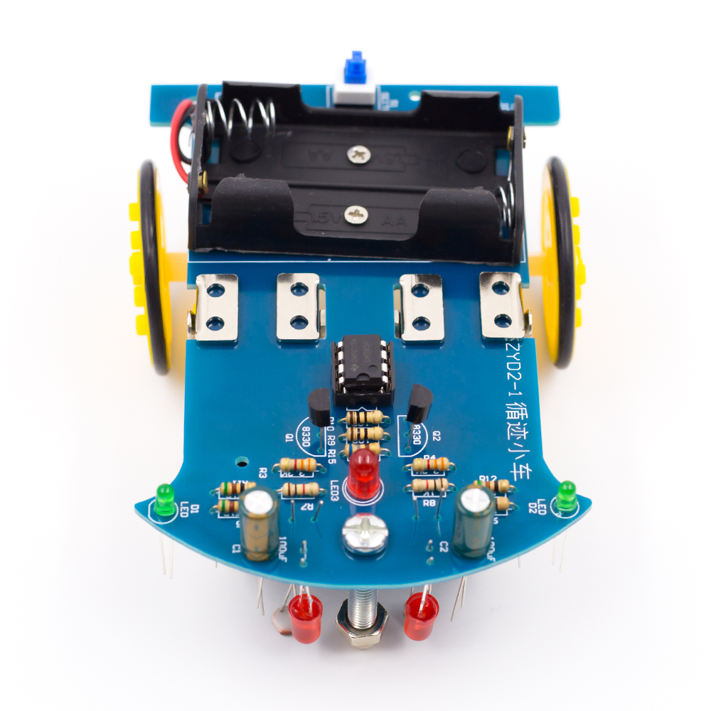
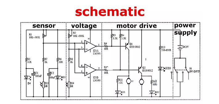
LM393 comparing two photosensitive resistance, when the imbalance (eg side pressure runway black) immediately control side of the motor stops rotating, the other side of the motor rotation acceleration, so that the car modification direction, return to the right direction, the whole process is a closed loop therefore rapid and sensitive control.
With the aim of simplifying the complex principle, we first have a by digital circuit to the intelligent tracking car, in the assembly process, we could not only familiar with the mechanical principle gradually can learn to: photocell, a voltage comparator, a motor drive circuit, and other related electronic knowledge.
Photosensitive resistance device:
This is light-sensitive resistance, it can detect the external light intensity, the stronger the outside light photosensitive resistance resistance is small, the outside light weaker resistance is greater when the red LED light projected on a white and black runway because reflection rate is different, the resistance value of the light-sensitive resistance will occur obvious difference for subsequent circuit control.
LM393 comparator integrated circuit:
LM393 is a dual voltage comparator integrated circuit, which consists of two independent precision voltage comparator. its role compare the two input voltage, based on the level of two input voltage change the level of output voltage. The output has two states: close to open or close to the low level, LM393 using open collector output, so it is necessary to add the pull resistance to output high level.
DC motor with gear reduction:
DC motor drive the car needs to slow down, otherwise to speed up the car, then ran too fast not control, and the deceleration torque is too small and could not run up. We specialize in custom of this type of motor is integrated with the reduction gear and greatly reducing the manufacture difficulty is very suitable for our use.
LM393 comparing two photosensitive resistance, when the imbalance (eg side pressure runway black) immediately control side of the motor stops rotating, the other side of the motor rotation acceleration, so that the car modification direction, return to the right direction, the whole process is a closed loop therefore rapid and sensitive control.
What's in the box?
1 x Electronic DIY Kit (batteries are not included)
Resources
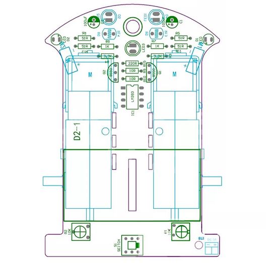
Assembly steps:
The first step: circuit part of the basic welding
The welding circuit part is relatively simple, the welding sequence according to the element height from low to high, the first 8 resistance welding, welding must use a multimeter to confirm whether the proper welding resistance, polar components such as transistors, green lights, definitely clear electrolytic capacitor polarity as reference element we are photo welding, welding capacitor short is the negative side of the insertion pin PCB screen printing shadow, green welding LED note long pin is positive, and the welding is not too long or easy bad welding, D4 D5 R13 R14 can temporarily do not weld, the integrated circuit chip can be inserted, preliminary after completion of welding check carefully prevent, be negligent.
Second step: mechanical assembly
The universal wheel screw is inserted into the PCB hole, and screwed into the universal wheel nut and a universal wheel. the battery box is stuck on the PCB by the double adhesive tape, the lead wire passes the PCB reserved Kong Han received PCB, the red line is connected with the 3 V positive power supply, and the yellow line is connected to the ground.
Mechanical part and assembly can be mounted first wheels, wheel consists of three pieces of black acrylic round tablets, assembly prior to exposing protective film, the inside of the wheel center hole grows circular hole, middle of the round plate diameter is relatively small, lateral wheel piece center hole Shiyuan, with two screw nuts fixed set good three round tablets, and black self-tapping screws fixed on the rotating shaft of the engine. Finally the silicone rubber tire sleeve on the wheel. Lead connection lead wire of the motor and the wheel assembly is the use of the glue on the PCB making position, attention wheels and the PCB edge retaining sufficient clearance, the motor leads are soldered to the PCB. Note that adequately longer lead, to avoid the motor rotation direction error is convenient for changing the lead wire of the order.
The third step: the installation of opto-electronic circuits
Photosensitive resistance and light-emitting diode (attention polarity) is the reverse installed on the PCB, and the ground distance of about 5mm, the distance between the light-sensitive resistance and light-emitting diode is also about 5mm. Finally can pass electrical test.
The fourth step: Vehicle debugging
In the battery box in 2 AA batteries, switches to dial in the "on", the car driving right reverse is traveling along the direction of the universal wheel, if hold the left side of the photosensitive resistance, the car to the right of the wheel rotation, Keep to the right of photosensitive resistance, the left side of the car wheel must turn, if car travel back can exchange connection of two motors at the same time. as one of the normal back on the other side as long as the exchange of the rear of the motor can be wiring.
Note: We don't supply any manuals, please note this before you buy this DIY kit.
A voltage regulator generates a fixed output voltage of a preset magnitude that remains constant regardless of changes to its input voltage or load conditions.
Specifications
- Integrated circuit
- Voltage regulator
- 5V
- Non insulated
What's in the box?
1 x TO-220 Voltage Regulator IC
You might also need a heatsink for your regulator
Resources
Understanding How a Voltage Regulator Works

Specifications
- DC Voltage 50V
- Value 1uF
- Size 11mm x 5mm
- Pitch 2mm
- pack of 10
What's in the box?
1 x Electrolytic Radial Capacitor 1uF 50V
Resources:
Theory
Introduction
Types

Arduino Mega is an ATmega2560 core microcontroller development board. Itself has 54 digital input/output terminals (14 PWM outputs), 16 simulation inputs, 4 UARTs (hardware serial ports), using the 16 MHz crystal oscillator. With the bootloader, download the program directly via USB without having to go through other external writers. Supply part of the optional USB power, or external power using a AC-to-DC adapter and battery.
Rapid growth due to open original code, as well as the concept of using Java (cross-platform) C language development environment for Arduino module. The Arduino can easily use the Arduino language with Flash or Processing ... software communication, to make multimedia interactive works. Arduino development IDE interface is based on open-source principles, allows you to download for use in projects.
Power supply design
There are two options for the power supply system of the Arduino Mega. USB direct power supply or external power supply. The power supply will be switched automatically. External supply AC-to-DC adapter or the battery can be selected on this control panel. Limit the voltage range of 6V ~~ 12V, but if the voltage supplied is less than 6V, I / O port may not be supplied to a voltage of 5V, and therefore not stable; If the voltage is greater than 12V, the regulator device may possibly overheat and damage the Arduino MEGA. It is therefore recommended that for the operating supply of 6.5 ~ 12V, the recommended power supply is 7.5V or 9V.
The development board have been rigorously tested at the factory.
Specifications
- Microcontroller: ATmega2560
- Operating voltage: 5V
- Input voltage (recommended): 7-12V
- Digital I/O pins: 54 (of which 14 provide PWM output)
- Analog input pins: 16
- DC current per I/O pin: 40 mA
- DC current for 3.3V Pin: 50 mA
- Flash Memory: 256 KB of which 4 KB is used by the bootloader
- SRAM: 8 KB
- EEPROM: 4 KB
- Clock Speed: 16MHz
What's in the box?
1 x Control board
1 x USB cable
Resources
Getting started with Arduino products
Please Note: These are 11mm standoffs. Different HATs can sometimes require different size standoffs - always measure before buying.
If you need different sizes have a look at the rest of our range of standoffs
The 11mm spacers in the kit fit between the Pi PCB and the HAT, and can be secured using the included M2.5 bolts and nuts.
What's in the box?
4 x M2.5 x 11mm Male to Female Standoffs
4 x M2.5 Bolts
4 x M2.5 Nuts