
Generic1


Features
- The IC conduction heatsink pad is 100% brand new and high quality.
- The pad has stickiness, good conduction, you can easily put it on IC and heatsink, you can fit it on LED IC SMD DIP or others.
Specific
- Material:conduction silicone
- Thickness: 2mm
- Weight:2.8kg
- Continuous Temp: -40 Degrees-260 Degrees
- Thermal Conductivity: 3.2w/m-K
- Breakdown Voltage: 4kv/mm
- Size:15x15x2mm
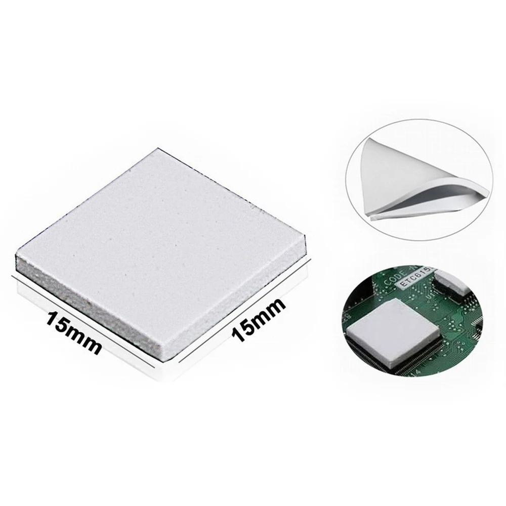
What's in the box?
1 x 36PCS Lot 15X15x2mm White SMD DIP IC Chip Heatsink Thermal Paste Pads

Features
- The IC conduction heatsink pad is 100% brand new and high quality.
- The pad has stickiness,good conduction,you can easily put it on IC and heatsink,
Specific:
- Material:conduction silicone
- Thickness: 2mm
- Weight:245g
- Continuous Temp: -40 Degrees-260 Degrees
- Thermal Conductivity: 3.2w/m-K
- Breakdown Voltage: 4kv/mm
- Size:25x25x2mm
- Package include:80x 25x25x2mm
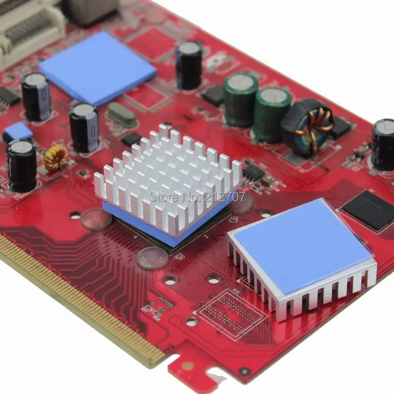
What's in the box?
1 x 80PCS Blue Thermal Heatsink Conductive Silicone Pad

Specifications:
- 5V DC fan for 3D Printers
- 40x40x10mm
What's in the box?
1 x 5V 40mm DC Fan for 3D Printer

The ULN2003 is one of the most common motor driver ICs, consisting of an array of 7 Darlington transistor pairs, each pair is capable of driving loads of up to 500mA and 50V. Four out of seven pairs are used on this board.
The board has four LEDs that show activity on the four control input lines (to indicate stepping state). They provide a nice visual when stepping.
The board also comes with an ON/OFF jumper to isolate power to the stepper Motor.
Specifications
- ULN2003 driver
- Suitable for microcontroller development
- Voltage: DC 5V
What's in the box?
1 x ULN2003 driver
Resources
How to control a ULN2003 stepper motor with Raspberry Pi
These are suitable for DIY projects and the Raspberry Pi pcb as the outside diameter is only 2.5mm that fits in the Pi mounting holes.
Brass standoffs are essential components in electronic projects, particularly in applications where circuit boards need to be securely mounted within an enclosure or chassis.
Here's how they are typically used:
Board Mounting: Brass standoffs are used to elevate and secure printed circuit boards (PCBs) within an electronic enclosure or chassis. They provide a stable platform for the PCB, preventing it from coming into contact with conductive surfaces that could cause short circuits.
Mechanical Support: Standoffs act as spacers between the PCB and the mounting surface, ensuring proper ventilation and preventing heat buildup. This is crucial for maintaining the integrity of sensitive electronic components.
Isolation: Brass standoffs help to electrically isolate the PCB from the chassis or enclosure. This isolation is essential for preventing electrical interference, reducing the risk of noise and signal degradation, and enhancing overall circuit performance.
Easy Access: Standoffs facilitate easy access to the PCB for maintenance, repairs, or upgrades. By raising the board above the mounting surface, technicians can easily reach components and make necessary adjustments without disassembling the entire system.
Vibration Dampening: In applications where vibration is a concern, brass standoffs can help dampen vibrations transmitted to the PCB, thereby reducing the risk of component failure or solder joint fatigue over time.
Grounding: Depending on the design, brass standoffs can also be used as grounding points for the PCB. By connecting the standoffs to the ground plane on the PCB, they provide a convenient and reliable grounding solution.
Overall, brass standoffs play a crucial role in ensuring the structural integrity, electrical isolation, and proper functioning of electronic systems. Their versatility and reliability make them indispensable components in a wide range of electronic projects.
What's in the box?
1 x Female Female Standoffs M2.5 x 16mm

Solder wire is a fusible metal alloy with a low temperature melting point used to permanently join two metals that have a higher melting point. Designed for use in electrical and electronic applications and to be environmentally friendly.
Specifications
- Roll Soldering Wire
- CONTAINS LEAD
- Diameter: 1.25 mm
- Net weight: 500g (approx.)
- Great For Electronics and Electrical Wiring
What's in the box?
1 x roll solder wire
Resources
Introduction to soldering
Video: How to solder properly
The secrets to good soldering

Solder wire is a fusible metal alloy with a low temperature melting point used to permanently join two metals that have a higher melting point. Designed for use in electrical and electronic applications and to be environmentally friendly.
Specifications
- Roll Soldering Wire
- CONTAINS LEAD
- 40% Tin
- Diameter: 2.0 mm
- Net weight: 15g (approx.)
- Great For Electronics and Electrical Wiring
What's in the box?
1 x 15g solder wire
Resources
Introduction to soldering
Video: How to solder properly
The secrets to good soldering
If your project is particularly resource-hungry then the Raspberry Pi may run a little hot. Cool it down with this nifty little oversized heatsink!
Simply remove the backing from the pre-applied thermal tape and stick it on top of the main processor chip.
Specifications
- 20mm x 20mm x 10mm
- Ideal for use with Raspberry Pi 5
- Matte black finish
- Made from anodised aluminium
- Comes with pre-applied thermal tape for easy installation
- Anodised non-conductive coating
What's in the box?
1 x CPU Heatsink
Note: At 10mm tall this heatsink may interfere with some HAT boards.

It cleans better than conventional sponges.
- Colour : Gold
- Size : 70mm x 69mm x 69mm
1 x Iron Tip Cleaner
Resources
Introduction to soldering
Video: How to solder properly
The secrets to good soldering

High quality anti-static wrist strap with grounding lead and clip to prevent ESD damage to sensitive electronic components or equipment. The wrist strap with alligator clip tip is fully adjustable. The inner conducting layer is made of stainless steel filaments. The lead is made from durable polyurethane coated coil cords.
Specifications
- High quality strain relief
- Soft elastic band for comfort
- Current limiting resistor 1M Ohm ± 5%
- Electro-scattering time 0.1sec
- Rinse resistant
- Weight: 25g
- Cable Length: 180cm
What's in the box?
1 x Anti-static wrist band with 180cm grounding lead
Need more I/O's on your microcontroller? You need an MCP23017 port expander chip!
It uses two i2c pins (which can be shared with other devices if required) and in exchange gives your microcontroller another 16 GPIO's! Each I/O pin can be configured as an in input, output or input with a pullup.
The chip can also be configured for interrupts for when an input changes, so you don't need to keep polling the chip!
This one comes in a DIP package, so it's great for breadboarding! You can also set the i2c address for up to 8 unique chips on the same i2c bus, which means you can daisy-chain these IC's to give you up to 128 I/O's!
Don't forget to grab a matching IC DIP socket for your project!
Features
- 16 bit remote bidirectional I/O port
- High-speed I2C interface
- Three hardware address pins to allow up to eight devices on the bus
- Configurable interrupt output pins
- INTA and INTB can be configured to operate independently or together
- Configurable interrupt source
- Polarity Inversion register to configure the polarity of the input port data
- External Reset input
- Low standby current: 1?A max.
Applications
- Automation & Process Control
- Automotive
- Clock & Timing
- Consumer Electronics
- Defence, Military & Aerospace
- Embedded Design & Development
- LED Lighting
- Industrial
- Motor Drive & Control
Specifications
- Bus Frequency: 1.7MHz
- Chip Configuration: 16bit
- IC Interface Type: I2C, Serial
- Interface Case Style: DIP
- No. of I/O's: 16
- No. of Pins: 28
- Supply Voltage Max: 5.5V
- Supply Voltage Min: 1.8V
What's in the box?
1 x MCP23017 Port Expander
Resources
These are suitable for DIY projects and the Raspberry Pi pcb as the outside diameter is only 2.5mm that fits in the Pi mounting holes.
Brass standoffs are essential components in electronic projects, particularly in applications where circuit boards need to be securely mounted within an enclosure or chassis.
Here's how they are typically used:
Board Mounting: Brass standoffs are used to elevate and secure printed circuit boards (PCBs) within an electronic enclosure or chassis. They provide a stable platform for the PCB, preventing it from coming into contact with conductive surfaces that could cause short circuits.
Mechanical Support: Standoffs act as spacers between the PCB and the mounting surface, ensuring proper ventilation and preventing heat buildup. This is crucial for maintaining the integrity of sensitive electronic components.
Isolation: Brass standoffs help to electrically isolate the PCB from the chassis or enclosure. This isolation is essential for preventing electrical interference, reducing the risk of noise and signal degradation, and enhancing overall circuit performance.
Easy Access: Standoffs facilitate easy access to the PCB for maintenance, repairs, or upgrades. By raising the board above the mounting surface, technicians can easily reach components and make necessary adjustments without disassembling the entire system.
Vibration Dampening: In applications where vibration is a concern, brass standoffs can help dampen vibrations transmitted to the PCB, thereby reducing the risk of component failure or solder joint fatigue over time.
Grounding: Depending on the design, brass standoffs can also be used as grounding points for the PCB. By connecting the standoffs to the ground plane on the PCB, they provide a convenient and reliable grounding solution.
Overall, brass standoffs play a crucial role in ensuring the structural integrity, electrical isolation, and proper functioning of electronic systems. Their versatility and reliability make them indispensable components in a wide range of electronic projects.
What's in the box?
1 x Male Female Standoffs M2.5 x 16mm
These are suitable for DIY projects and the Raspberry Pi pcb as the outside diameter is only 2.5mm that fits in the Pi mounting holes.
Brass standoffs are essential components in electronic projects, particularly in applications where circuit boards need to be securely mounted within an enclosure or chassis.
Here's how they are typically used:
Board Mounting: Brass standoffs are used to elevate and secure printed circuit boards (PCBs) within an electronic enclosure or chassis. They provide a stable platform for the PCB, preventing it from coming into contact with conductive surfaces that could cause short circuits.
Mechanical Support: Standoffs act as spacers between the PCB and the mounting surface, ensuring proper ventilation and preventing heat buildup. This is crucial for maintaining the integrity of sensitive electronic components.
Isolation: Brass standoffs help to electrically isolate the PCB from the chassis or enclosure. This isolation is essential for preventing electrical interference, reducing the risk of noise and signal degradation, and enhancing overall circuit performance.
Easy Access: Standoffs facilitate easy access to the PCB for maintenance, repairs, or upgrades. By raising the board above the mounting surface, technicians can easily reach components and make necessary adjustments without disassembling the entire system.
Vibration Dampening: In applications where vibration is a concern, brass standoffs can help dampen vibrations transmitted to the PCB, thereby reducing the risk of component failure or solder joint fatigue over time.
Grounding: Depending on the design, brass standoffs can also be used as grounding points for the PCB. By connecting the standoffs to the ground plane on the PCB, they provide a convenient and reliable grounding solution.
Overall, brass standoffs play a crucial role in ensuring the structural integrity, electrical isolation, and proper functioning of electronic systems. Their versatility and reliability make them indispensable components in a wide range of electronic projects.
What's in the box?
1 x Male Female Standoffs M2.5 x 16mm
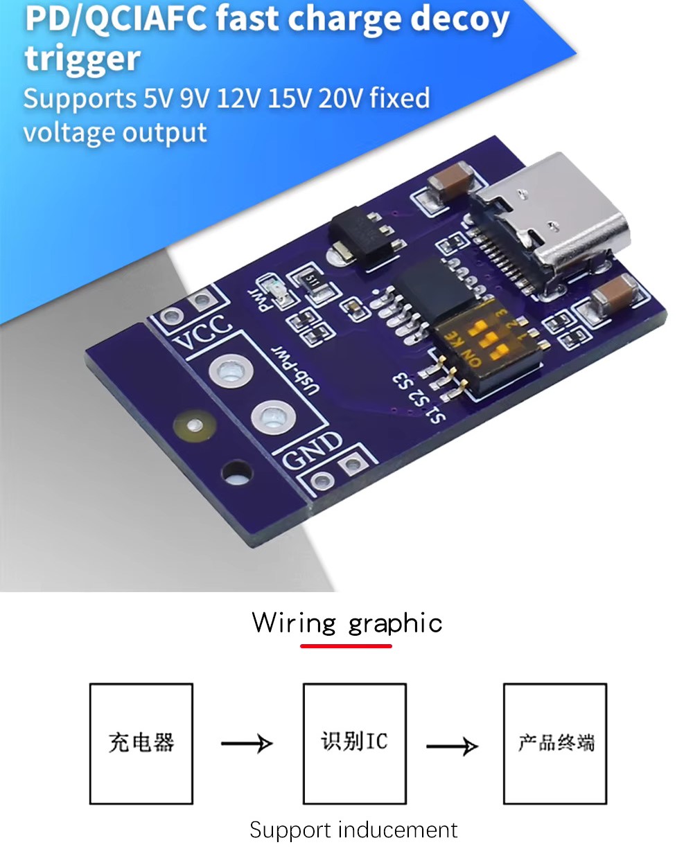
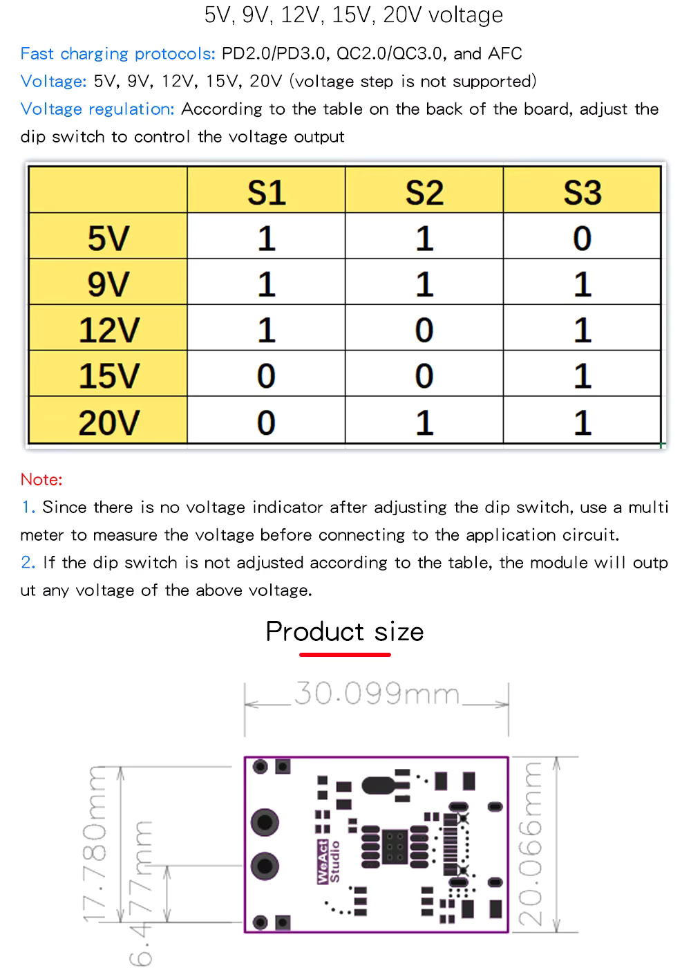
What's in the box?
1 x PD/QCIAFC Fast charge decoy trigger

Features
- Display Colour: Red
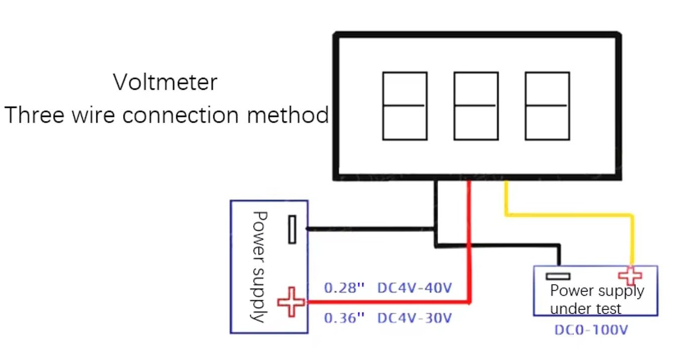
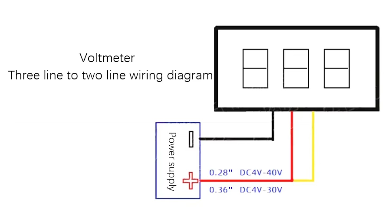
- The black line connects to the negative electrode of both the power supply and tested power supply, red line connects to positive pole of power supply, white line connects to positive pole of tested power supply
- Material: Plastic Shell
- Display Digit: 3
- Power: 5V, 9V, 12V or 24V without voltage regulation(Working voltage: 4.5V-30V)
- Measuring Range: DC 0V - 100V
- Operating current: 20mA
- Installation dimension: Approx 23mm x 10mm

Features
- Display Colour: Yellow
- The black line connects to the negative electrode of both the power supply and tested power supply, red line connects to positive pole of power supply, white line connects to positive pole of tested power supply
- Material: Plastic Shell
- Display Digit: 3
- Power: 5V, 9V, 12V or 24V without voltage regulation(Working voltage: 4.5V-30V)
- Measuring Range: DC 0V - 100V
- Operating current: 20mA
- Installation dimension: Approx 23mm x 10mm

Features
- Display Colour: Blue
- The black line connects to the negative electrode of both the power supply and tested power supply, red line connects to positive pole of power supply, white line connects to positive pole of tested power supply
- Material: Plastic Shell
- Display Digit: 3
- Power: 5V, 9V, 12V or 24V without voltage regulation(Working voltage: 4.5V-30V)
- Measuring Range: DC 0V - 100V
- Operating current: 20mA
- Installation dimension: Approx 23mm x 10mm

Features
- Display Colour: Green
- The black line connects to the negative electrode of both the power supply and tested power supply, red line connects to positive pole of power supply, white line connects to positive pole of tested power supply
- Material: Plastic Shell
- Display Digit: 3
- Power: 5V, 9V, 12V or 24V without voltage regulation(Working voltage: 4.5V-30V)
- Measuring Range: DC 0V - 100V
- Operating current: 20mA
- Installation dimension: Approx 23mm x 10mm

3D printing plastics often have low yield strength and cannot reliably produce threaded features. Embedded metal nuts provide stronger and more precise threading for hidden fasteners. The nut melts and reflows the plastic around it, enhancing its strength. However, there are design constraints - the nut must be on a part face and cannot be reinforced beyond the plastic's properties.
Specifications
- Thread Size: M3
- Height: 4mm
- Outer Diameter: 5mm
- Material: Brass
What's in the box?
1 x Brass Heat Threaded Inserts Embedment Nut

Specifications
- Module Type: Buck converter
- Input: 8V to 90V
- Output: 5V
- Output current: 5A(max)
- Conversion efficiency: up to 96%
- Size: 46mm x 32mm x 18mm
1 x 5V 5A Power Adapter