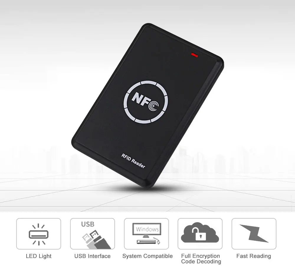
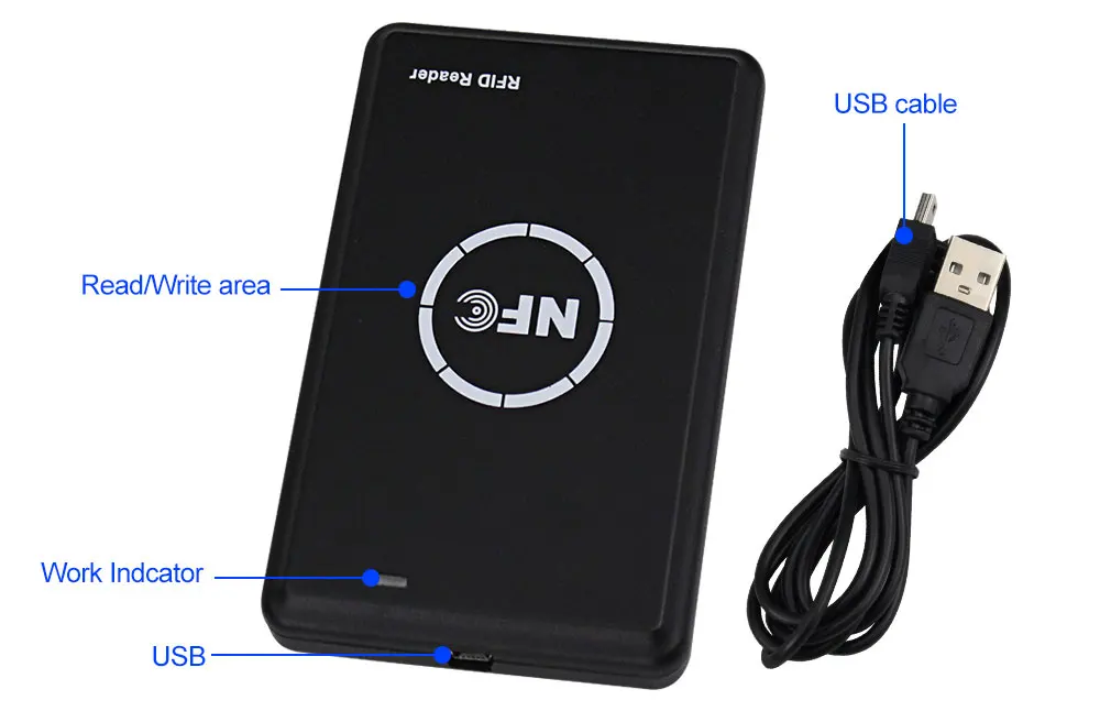
Generic1
Here is a video from CNC Kitchen, he teaches how to install embedment nuts into 3D-printed parts.
3D printing plastics often have low yield strength and cannot reliably produce threaded features. Embedded metal nuts provide stronger and more precise threading for hidden fasteners. The nut melts and reflows the plastic around it, enhancing its strength. However, there are design constraints - the nut must be on a part face and cannot be reinforced beyond the plastic's properties.
Specifications
- Thread Size: M3
- Height: 4mm
- Outer Diameter: 5mm
- Material: Brass
What's in the box?
1 x Brass Heat Threaded Inserts Embedment Nut
Specifications
- USB 4
- PD3.1
- Resolution: 0.1V/0.1W
- 40Gbps transmission
- 8K/60Hz HD
- Display current/voltage/power
- Dimensions 12.6mm x 32.8mm x 7.4mm
- Type-C bidirectional input-output
What's in the box?
1 x USB-C Voltage/Current/Power Meter
Specifications
- Size: 62mm(L)x44mm(W)x23mm(H)
- Input Voltage (Trigger): DC 3-32V
- Output Voltage(Line): AC 24-380V
- Output Current(Line): 60 A
- On Voltage: ≤1.6V
- OnOff Time: ≤10ms
- Control Current: 3-35mA
- Transparent Lid Included: Yes
What's in the box?
1 X 60A SSR-50DA Solid State Relay With Cover
Resources
Datasheet available at https://cdn.sparkfun.com/datasheets/Components/General/SSR40DA.pdf
Depending on how hard your relay works, you might want to add a heat sink to it.
Q:During continuity testing with my multimeter why does my relay on the AC side not switch on?
A: The below info was found at http://www.crydom.com/en/tech/newsletters/solid statements - bench test an ssr.pdf
A multimeter determines impedance by injecting a small amount of voltage through it's probes into the circuit being tested. It then measures the current flowing through the probes and calculates resistance. Easy enough; Resistance = Voltage / Current! However, as we just discussed above, a solid state relay’s output turns on by “stealing” a bit of voltage from the AC mains in order to supply current to the gate of the SCRs. Simply put, if the AC mains is not connected to the relay then the output cannot turn on. Since the voltage and current produced by a multimeter is not sufficient enough to turn on the SCRs, the output of a solid state relay will remain in the off state; even with the input signal applied. As a result, SSRs will sometimes fail an incoming inspection because the engineer expects to see a significant change in the output impedance when they turn on the relay.The most effective way to bench test a solid state relay is to construct a simple test circuit consisting of a DC power supply or battery (a 9Vdc battery will work fine in most cases ) and a 60W or 100W light bulb.
Product Features
1) Compliant with CCID
2) Compliant with PC/SC
3) Support IC/ID dual frequency replication
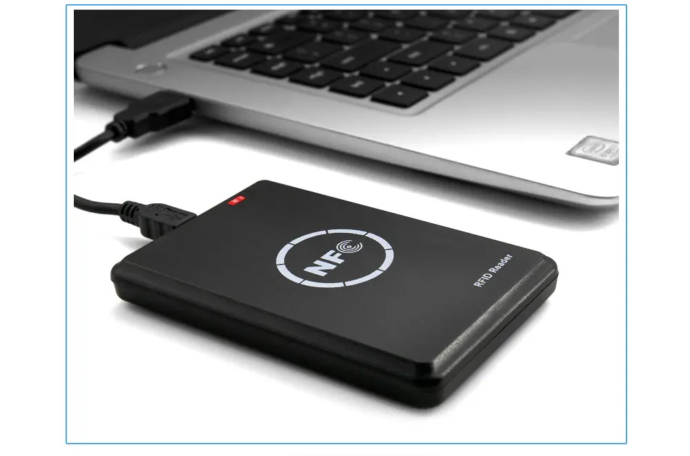
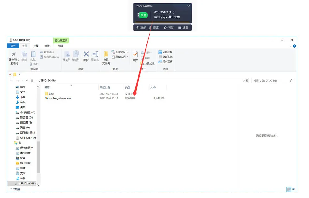
4) Driver-free, no need to download software installation
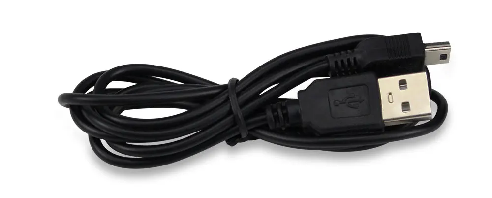
5) When connect the RFID Reader to the computer with the USB cable, then can find the software.
6) Support ID125K, 8800, 5200, 4305, 5577, 8265 card.
7) Support UID FUID CUID UFUID IC semi-encrypted card, IC full encryption card.
8) Has USB full speed interface
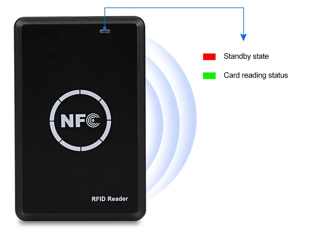
9) Two-color LED light prompt (red light is standby, green is working)
10) Built-in buzzer "beep" sound reminder
How to use the card reader?


Hot Question:
1) Where can i download the software?
Answer: You can download the software via this link:http://www.nsccn.com/download/soft/nfc/nfcPro_wbw.exe
2) Which chip inside in the 5pcs blue keyfobs and 5pcs white cards?
Answer: If you buy the RFID copier + 5pcs UID keyfobs + 5pcs T5577 cards. The 5pcs UID keyfobs is working with 13.56MHz frequency, used to copy the MF 1k card. The 5pcs T5577 cards is working with 125KHz frequency, used to copy the EM4100, TK4100 cards. They are different type card.
3) Why the 5pcs cards in the package read failure?
Answer: Please don't worry, these 5pcs white cards is T5577 (EM4305) type, they haven no data before write. They will can be read successfully after finished written from your TK4100 or EM4100 type card. Thank you.
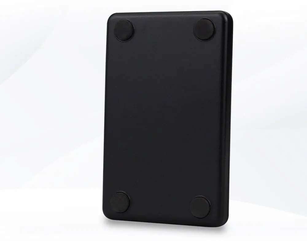
What's in the box?
1 x RFID Copier Duplicator 125KHz Key fob NFC Smart Card Reader Writer 13.56MHz Encrypted Programmer USB UID T5577 EM4305 Cards Tags
Product size: 35.5 * 17 * 8.3 mm
Input voltage range: 6 to 26 v
Output voltage: 5.2 V (consider charging line loss, output is about 5.2 V, the load end is around 5 V)
Limit the output current: 3 a (in the absence of radiator, stable output current limit is 2 a)
Note 1: is the cathode can't meet the, and the input voltage can't more than 26 v, otherwise it will result in the chip damage!
Note 2: in current work, not touch on the circuit board sampling resistor, IC, or may result in output voltage mutation damage equipment!
What's in the box?
1 x 9V 12V 24V to 5V 3A USB step-down voltage regulator module DC-DC Converter
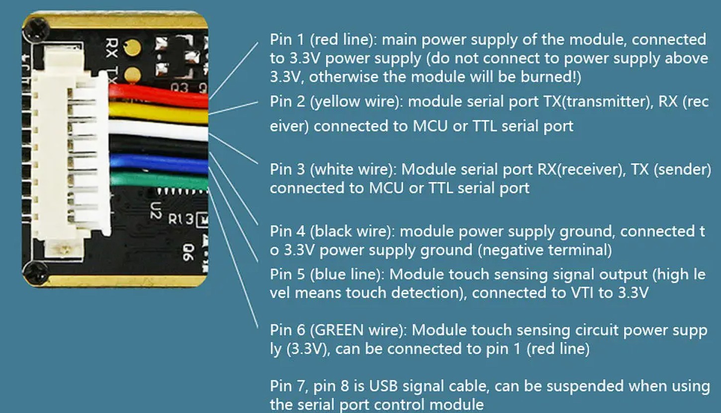
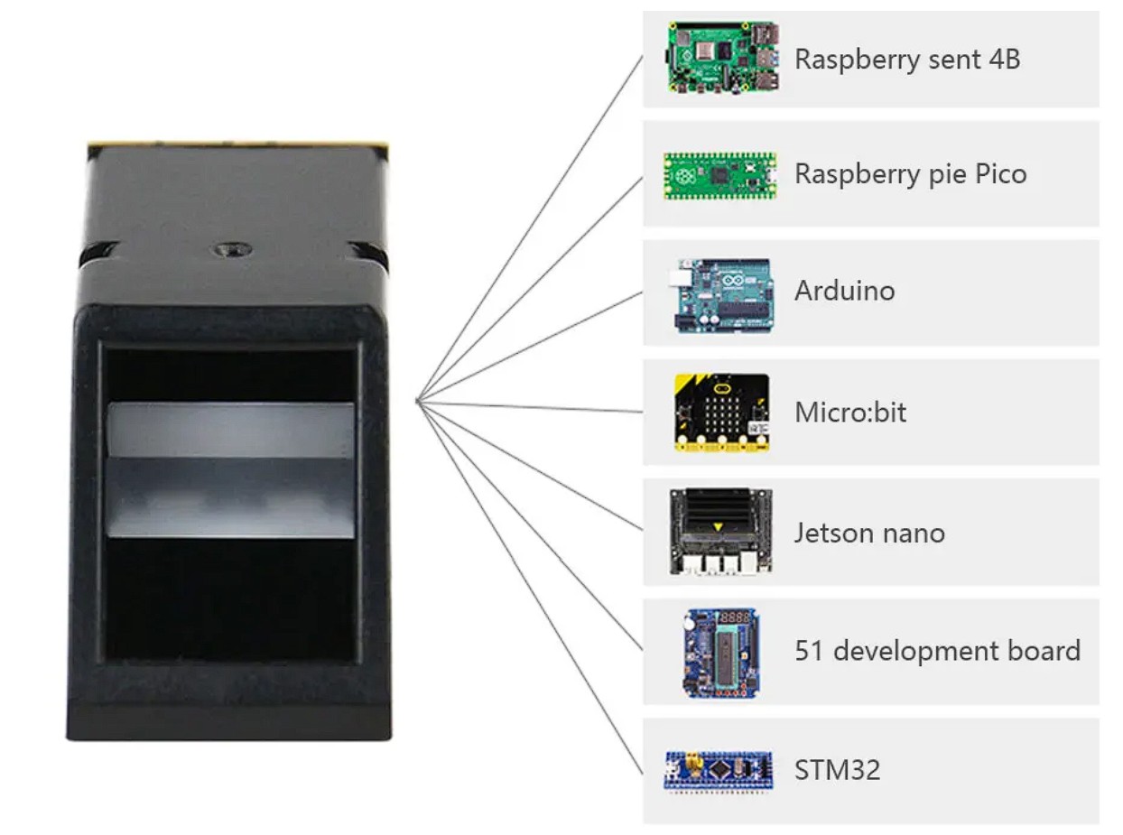
What's in the box?
1 x DC-DC Vehicle Charging Board 8V-35V to 5V 8A Power Supply Depressurization Module 4 port USB Output mobile Charger
The RF Remote is a 433MHz Wireless 4 Buttons Push Cover Remote. This Wireless 4 Buttons 433Mhz remote control can remotely control any Sonoff RF products. It’s suitable for long distance and multiple switch control. The remote controller is compatible with 433MHz products like the light switches, RF Bridge, Basic RF and 4Ch Pro RF R2.
Note: This RF Remote contains a battery (A27)
This product can work with our smart home products: Sonoff RF, Sonoff 4CH Pro, Sonoff RF Bridge 433, Sonoff TX2 and TX 3 light Switches.
What's in the box?
1 x 433Mhz Wireless Remote
Resources
These are suitable for DIY projects and the Raspberry Pi pcb as the screw outside diameter is only 2.5mm that fits in the Pi mounting holes.
Brass standoffs are essential components in electronic projects, particularly in applications where circuit boards need to be securely mounted within an enclosure or chassis.
Here's how they are typically used:
Board Mounting: Brass standoffs are used to elevate and secure printed circuit boards (PCBs) within an electronic enclosure or chassis. They provide a stable platform for the PCB, preventing it from coming into contact with conductive surfaces that could cause short circuits.
Mechanical Support: Standoffs act as spacers between the PCB and the mounting surface, ensuring proper ventilation and preventing heat buildup. This is crucial for maintaining the integrity of sensitive electronic components.
Isolation: Brass standoffs help to electrically isolate the PCB from the chassis or enclosure. This isolation is essential for preventing electrical interference, reducing the risk of noise and signal degradation, and enhancing overall circuit performance.
Easy Access: Standoffs facilitate easy access to the PCB for maintenance, repairs, or upgrades. By raising the board above the mounting surface, technicians can easily reach components and make necessary adjustments without disassembling the entire system.
Vibration Dampening: In applications where vibration is a concern, brass standoffs can help dampen vibrations transmitted to the PCB, thereby reducing the risk of component failure or solder joint fatigue over time.
Grounding: Depending on the design, brass standoffs can also be used as grounding points for the PCB. By connecting the standoffs to the ground plane on the PCB, they provide a convenient and reliable grounding solution.
Overall, brass standoffs play a crucial role in ensuring the structural integrity, electrical isolation, and proper functioning of electronic systems. Their versatility and reliability make them indispensable components in a wide range of electronic projects.
What's in the box?
1 x Male Female Standoff M2.5 x 7mm
Tired of useful gadgets? Meet the Useless Box! Flip the switch, and a tiny mechanism pops out to flip it right back off. It's perfectly pointless, delightfully disruptive, and guaranteed to spark a smile (or a chuckle of confusion). The ideal desk toy for those who appreciate the absurd.
What's in the box?
1 x Mini useless box Black
This is a small board with a load switch that allows a Raspberry Pi to automatically temperature control a fan (not included) via GPIO3.
It's an affordable, compact and light way to add smart temperature control to your own Raspberry Pi enclosure or project, and can be used to toggle power for other devices using up to 1A as well.
Compatible with:
What's in the box?
1 x Fan Controller
Resources
How to use
The Fan controller should be connected to the first 6 pins on the header where it uses 5V, GND and GPIO 3 (see images).
To automatically cool your Raspberry Pi when it starts to warm up, add the following to your /boot/config.txt and restart the Pi. You can change the value to make the fan turn on at different temperatures too:
dtoverlay=gpio-fan,gpiopin=3,temp=80000
Note: Raspberry Pi and Fan not included
Protect and showcase your Raspberry Pi with this durable, precision-cut acrylic case. Designed for optimal ventilation and full access to ports, this sleek enclosure keeps your Pi safe while maintaining a clean, modern look. Easy to assemble with included mini screwdriver.
Features
- Compatible with Raspberry Pi 5 and multifunctional adapter
- Sufficient space to fit the Active Cooler
- Transparent panels for visibility and aesthetics
- Ventilation slots for efficient heat dissipation
- Cutouts for all GPIO, USB, HDMI, and power ports
- Lightweight, stackable, and perfect for DIY projects
- Material: Acrylic
- Colour: Transparent (Remove the protective film)
- Requires Customer Assembly
What's in the box?
6 x acrylic plate parts(peel off the protective film on both sides)
4 x M2.5x5+5 standoffs to fit under the Pi screw part facing upwards
4 x M2.5x7 standoffs to fit under the adapter board screw part facing upwards
4 x FF M2.5 x 18 standoff to fit on top of the Pi
2 x FF M2.5x16 Brass standoffs to fit on the outer side of the adapter
2 x FF M2.5x5 brass standoffs to fit on the inner side of the adapter
14 x M2.5x6 screws - 8 for the bottom and 6 for the top of the case
4 x rubber feet
1 x mini screwdriver
Tip: It helps to tighten all the screws only once they have all been fitted loosely in place
This Reflective IR Sensor is a simple plastic casing with two elements - an IR LED and an IR phototransistor. You can control the IR LED and turn it on to bounce IR off objects to determine their reflectivity. White & light colored stuff will bounce the light, so you can detect it.
Specifications
Colour | Black blue |
Material | Plastic iron |
Specification | Detecting range: 0.591" (15mm); Detecting method: Reflective; Collector Emitter Voltage: 70V; Collector Current: 100mA; Forward Current: 60mA; Output type: Phototransistor; Working temperature: -25~85'C |
Features | Compact construction, sense the presence of an object by using the reflective IR beam from the object |
Application | Perfect for line tracking robot car DIY project |
What's in the box?
5 x TCRT5000L Reflective switch
Resources
How to use TCRT5000 switches
This RTC module is specifically designed for the Raspberry Pi. It communicates with Raspberry Pi through the I2C bus and includes a Maxim DS1307 and CR1220 button cell (not included) on the board to keep a real-time clock for a long time after the Pi has powered down
Simply plug this tiny module into the GPIO header on the Raspberry Pi and away you go!
Specifications
- RTC module: DS1307
- Battery model: CR1220 button cell
- Operating Voltage: 3V to 5V
- I2C address: 0x68
- Clock precision: ±2ppm (0~40°C)
- Unit information: Second, Minute, Date, Week, Month and Year
- Two calendar clock
- Operating temperature: -10°C至+85°C
- Compatible with Raspberry Pi B/A+/B+/2B/3B/4B
- Interface: 2*5p 2.54mm
What's in the box?
1 x RTC Module
You will also need a CR1220 battery
Resources
- Joystick Size: Approx. 95x60x100mm
- Encoder Board Size: Approx. 85x35mm
- USB Cable Length: Approx. 1.8m
- Colour: one set Red and one set Black
We have tested this unit on Raspberry Pi using Retropie and a Windows 7 PC using MAME.
What's in the box?
This kit contains two sets of the following:
1 x Encoder Board
1 x USB Cable
1 x 5 pin Cable for Joystick
1 x 5 Pin Joystick
8 x 30mm Push Buttons
2 x 24mm Push Buttons
10 x Cables for Buttons
Resources
Get Retropie on the Raspberry Pi
ThePiHut setup guide
UNO R3 is a microcontroller board based on the ATmega328P.
The Arduino Uno R3 comes in two models; the normal version and the SMD version. In the SMD version you have the Atmega328 controller IC as an SMD chip soldered into the board, whereas in the normal version the IC is held on the Arduino by an IC Holder.
Features
- 14 digital input/output pins (of which 6 can be used as PWM outputs)
- 6 analog inputs
- a 16 MHz quartz crystal
- a USB connection
- a power jack
- an ICSP header
- a reset button.
It contains everything needed to support the microcontroller. Simply connect it to a computer with a USB cable or power it with a AC-to-DC adapter or battery to get started.
What's in the box?
1 x Arduino Uno SMD
1 x Headers
1 x USB cable (Cable colour might differ prom product pic)
Resources
Getting started with Arduino products
This is a Mini Real-Time Clock module, it's design for the Raspberry Pi, but it can also be used with an Arduino.
Simply plug this tiny module into the GPIO header on the Raspberry Pi and away you go!
Specifications
- DS3231 RTC IC
- Self-adjust 3.3V and 5V
- Size: 14mm x 14mm x 12 mm
Features
- Smaller
- Work in 3.3V and 5V
- Supported Raspberry Pi and Arduino
What's in the box?
1 x RTC Module
1 x Battery
Resources
The only downside is they use the Dallas 1-Wire protocol, which is somewhat complex, and requires a bunch of code to parse out the communication. If you want something really simple, and you have an analog input pin, the TMP36 is trivial to get going.
We toss in a 4.7k resistor, which is required as a pullup from the DATA to VCC line when using the sensor.
Cable specs
- Stainless steel tube 6mm diameter by 30mm long
- Cable is 36" long / 91cm, 4mm diameter
- Contains DS18B20 temperature sensor
- If your sensor has four wires - Red connects to 3-5V, Black connects to ground and White is data. The copper wire is soldered to the wire shielding
- If your sensor has three wires - Red connects to 3-5V, Blue/Black connects to ground and Yellow/White is data
DS18B20 Technical specs
- Usable temperature range: -55 to 125°C (-67°F to 257°F)
- 9 to 12 bit selectable resolution
- Uses 1-Wire interface- requires only one digital pin for communication
- Unique 64 bit ID burned into chip
- Multiple sensors can share one pin
- ±0.5°C Accuracy from -10°C to 85°C
- Temperature-limit alarm system
- Query time is less than 750ms
- Usable with 3.0V to 5.5V power/data
What's in the box?
1 x DS18B20 Digital temperature sensor
1 x 4.7k resistor
Resources
Adafruit's Raspberry Pi Lesson: DS18B20 Temperature Sensing
Thermoelectric coolers (TEC or Peltier) create a temperature differential on each side. One side gets hot and the other side gets cool. Therefore, they can be used to either warm something up or cool something down, depending on which side you use. You can also take advantage of a temperature differential to generate electricity.
This Peltier works very well as long as you remove the heat from the hot side. After turning on the device, the hot side will heat quickly, the cold side will cool quickly. If you do not remove the heat from the hot side (with a heat sink or other device), the Peltier will quickly reach stasis and do nothing. We recommend using an old computer CPU heatsink or other block of metal to pull heat from the hot side. We were able to use a computer power supply and CPU heatsink to make the cold side so uncomfortably cold we could not hold our finger to it.
Note: It is imperative that a heat sink is used on the hot side of the module. Running the module without one can cause damage to this part. If it’s too hot to comfortably touch, you’re in the danger zone!
Specifications
- Model: TEC1-12715
- Colour: white
- Couples: 127
- Voltage: 12V
- Imax: 12A (15A at startup with maximum voltage 15.5V)
- Max power consumption: 231W
- Tmax: 70°C
- Qcmax △T=0(W): 137W
- Size: 40 x 40 x 3.3mm
- Weight: 50g
What's in the box?
1 x cooler plate module(40mm x 40mm)
Resources
- Learn about TECs (Tom’s Wiki)
- Learn about thermoelectric effect (Wikipedia)
Standard Single Head Power Cable-1.8m-Standard computer power cable with 3-prong plug on one end and kettle plug connection on the other., OEM, No Warranty
Standard 3 prong South African Plug 16Amp fuse plug on one end and the IEC (kettle plug) connection on the other. Plugs directly into computers, certain monitors and various power supply units. Also known as Power Cord (Kettle Cord) 3 Pin South African, One IEC Connector, 1.8 Meters
• Connects a PC to a 220 volt AC power outlet
• Single CIEC standard compliant moulded PC power plug
• Can be used on standard domestic 3 pin AC power outlets
• 220 Watt rating for SLI and multi-rail power supply use
• 1.8metre Long
What's in the box?
1 x power cord with plug