
Generic1


Please Note: These are 11mm standoffs. Different HATs can sometimes require different size standoffs - always measure before buying.
If you need different sizes have a look at the rest of our range of standoffs
The 11mm spacers in the kit fit between the Pi PCB and the HAT, and can be secured using the included M2.5 bolts and nuts.
What's in the box?
4 x M2.5 x 11mm Male to Female Standoffs
4 x M2.5 Bolts
4 x M2.5 Nuts

It has four digits and a decimal point on each digit, designed for numeric output, so you can use it to add a clock, timer or counter into your next project.
These displays are multiplexed, common-cathode. What that means it that you can use a 74HC595 or just 8 microcontroller pins if you can spare them to control the 8 anodes (7-seg decimal) at about ~15mA each, and then connect NPN transistors or a TPIC6B595 to the cathodes to sink the 8*20mA = ~120mA maximum per digit.
This is an ultra bright RED colour.
Specifications
- 100mcd
- 14.2mm (0.56") digit height
- Color: red (630nm)
- Common cathode display
- Maximum power dissipation per segment: 66mW
- Maximum pulse peak forward current per segment (1/10th duty cycle, 0.1ms pulse width): 100mA
- Maximum forward current per segment: 20mA
- Maximum reverse voltage: 5V
- Maximum reverse current: 20µA
- Typical forward voltage: 2.1V at 20mA
- Maximum forward voltage: 2.5V at 20mA
- Operating temperature range: -30°C - 70°C
- Typical luminous intensity: 20mcd
What's in the box?
1 x Four Digit Seven Segment Display Red
Resources

- This product is mainly used for water metering
- High amplitude ≥ 4.6V
- Low amplitude ≤ 0.5V
- Electric strength 1250V/min
- Insulation resistance ≥ 100MΩ
- Hydrostatic pressure testing ≤ 2.0Mpa
Specifications
- The lowest rated working voltage: DC4.5 5V-24V
- Maximum operating current: 15 mA (DC 5V)
- Working voltage range: DC 5~18 v
- Load capacity: ≤ 10 mA (DC 5V)
- Use temperature: ≤ 80°C
- Operating humidity range: 35%~90%RH (no frost)
- Allowing pressure: pressure 2.0Mpa
- Temperature: -25~ 80 °C
- External threads: 1/2"
- Outer diameter: 20mm
- Intake diameter: 9mm
- Outlet diameter: 12mm
Application
Water heaters, water vending machines, flow measurement
What's in the box?
1 x Water flow sensor
Resources
Flow sensor Wiki
An instructable on how to use the Flow Sensor with Arduino
Adafruit experiment connecting the Flow Sensor to a Raspberry Pi
https://www.ardumotive.com/water-flow-sensor-en.html
RPi: https://www.youtube.com/watch?v=8JXd-2_zJQ0

Please note: Pic is for illustration purposes only
The 1N400x (or 1N4001 or 1N4000) series is a family of popular one-ampere general-purpose silicon rectifier diodes commonly used in AC adapters for common household appliances. Its blocking voltage varies from 50 volts (1N4001) to 1000 volts (1N4007).
Specifications
- Average forward current is 1A.
- Non-repetitive peak current is 30A.
- Reverse current is 5uA.
- RMS reverse voltage is 35V.
- Peak repetitive Reverse voltage is 50V.
- DO-41 Package.
What's in the box?
10 x diodes
Resources
Intoduction
Basics, Types, Characteristics, Applications & Packages

Thermoelectric coolers (TEC or Peltier) create a temperature differential on each side. One side gets hot and the other side gets cool. Therefore, they can be used to either warm something up or cool something down, depending on which side you use. You can also take advantage of a temperature differential to generate electricity.
This Peltier works very well as long as you remove the heat from the hot side. After turning on the device, the hot side will heat quickly, the cold side will cool quickly. If you do not remove the heat from the hot side (with a heat sink or other device), the Peltier will quickly reach stasis and do nothing. We recommend using an old computer CPU heatsink or other block of metal to pull heat from the hot side. We were able to use a computer power supply and CPU heatsink to make the cold side so uncomfortably cold we could not hold our finger to it.
Note: It is imperative that a heat sink is used on the hot side of the module. Running the module without one can cause damage to this part. If it’s too hot to comfortably touch, you’re in the danger zone!
Specifications
- Model: TEC1-12715
- Colour: white
- Couples: 127
- Voltage: 12V
- Imax: 12A (15A at startup with maximum voltage 15.5V)
- Max power consumption: 231W
- Tmax: 70°C
- Qcmax △T=0(W): 137W
- Size: 40 x 40 x 3.3mm
- Weight: 50g
What's in the box?
1 x cooler plate module(40mm x 40mm)
Resources
- Learn about TECs (Tom’s Wiki)
- Learn about thermoelectric effect (Wikipedia)
UBEC's (Universal Battery Eliminator Circuit's) are simply DC to DC step down voltage regulators! This UBEC is perfect for the Raspberry Pi, as it's able to take high voltages (5.5V up to 26V), and outputs a consistent safe voltage of 5V at up to 3A nominal or 5A max! The Hobbywing 5V 3A UBEC is a switch-mode type, which results in it being much more efficient than linear type UBEC's (so your batteries will last longer!)
UBEC's are perfect for applications where you plan to use the Raspberry Pi in a circuit with high voltages such as robots where you'll be driving motors!
Due to the voltage drop caused by the Raspberry Pi, it is recommended to input a minimum of 6.5V from your Batteries to receive a stable 5V output. Anything lower than 6.5V will result in a low voltage warning on the Pi.
Please Note. The Hobbywing UBEC can be set to output either 5V or 6V using an onboard jumper select! Please DOUBLE CHECK your output voltage is correct before connecting your microcontroller or circuit!
Features
- Designed with an advanced switch mode DC-DC regulator IC.
- Battery polarity reversal protection.
- A metal shield covers almost all the electronic components, and a specially made filter is attached to the output wires to significantly reduce the electromagnetic interference.
- The working status is shown by an indicator (LED), which lights when the output is in normal range.
- Output Voltage: 5V@3A or 6V@3A (Changeable with an output-voltage select jumper)
- Continuous output current: 3 Amps
- Maximum output current: 5 Amps
- Input: 5.5V - 26V (2 - 6 cells lithium battery pack or 5 - 18 cells NiMH /NiCd battery)
- Size: 43mm*17mm*7mm (L*W*H)
- Weight: 11g
What's in the box?
1 x Hobbywing converter
Powering Raspberry Pi tutorial here: https://www.modmypi.com/blog/using-a-ubec-with-a-raspberry-pi

This handy Ethernet extension cable will make it easy for you to enclose a device that has an Ethernet port. It's extra short (15cm), so perfect for mounting your Raspberry Pi, Beagle Bone, Arduino etc. into a box!
The jack half has two mounting 'ears' with M3 screws installed, 8mm apart. The ears are flexible so the holes don't have to be drilled very precisely.
Features
- Length between connectors: 15cm
- Colour: Black
- RJ45 Male to Panel Mount RJ45 Female
- Patch Cable
- M3 Mounting Ears (Two M3 x 6mm Screws Included)
What's in the box?
1 x panel mount ethernet adapter
- Dual H-Bridges - run four solenoids, two DC motors, or one uni-polar or bi-polar stepper motor
- Output Current: 600mA per channel (1.2A Max)
- No of Channels: 4
- Input: 5V Logic
- Supply Voltage Range: 4.5V to 36V
- No. of Pins: 16
- Operating Temperature Range: 0°C to 70°C
What's in the box?
Tutorials
Controlling a Stepper Motor with the L293D

MS wind vane as used in the Raspberry Pi foundation weather station project to measure wind direction.
Hack this component to form part of your weather station.
Specifications:
| Range | 0 to 360° (352° electrical, 8° open) |
| Accuracy | 1% of full scale |
| Operating Voltage | 10-36 VDC |
| Sensitivity | 1 m/s (2.2 mph) |
Resources:
View the project details here
And some more help here
Article specific to the wind vane only

MS rain gauge as used in the Raspberry Pi foundation weather station project to measure rainfall.
Hack this component to form part of your weather station.
Specifications
- Rain gauge measures 0.011" (0.2794 mm) increments per bucket tip
What's in the box?
1 x Rain Gauge
Resources
View a weather project details here

Specifications
- Power: 1W
- Voltage: 5V
- Material:Monocrystalline Silicon
- Size: 60x110mm
What's in the box?
1x 5V Solar panel

Specifications
- Voltage: DC 12V
- Current: 0.08A
- Size: 40mm x 40mm x 10mm
- Colour: Black

The aluminum heat sink can reduce the risk of hardware failure due to overheating.
Better efficiency if used with a fan
Ideal for use with your Nema 17 stepper motor.
Specifications
- Material: Aluminum
- Colour: Black
- Weight: 20g
- Size: 40 x 40 x 11mm
Applications
LED, Power IC, Memory, Transistor, stepper motor etc.
This heatsink comes with Heatsink Adhesive Tape.
What's in the box?
1 x Aluminum heat sink 40 x 40 x 11mm

Keep all kinds of cord-cables well organized and tidy in place, used to tie up speaker cables, guitar cables, TV cables, microphone mic, computer cables, and much more.
Can write directly onto the tag, help you know which cable is headed where and remember which cable is which.
Using a sharpie to Write make a perfect combination to ending cable madness! can use them in the garden, office, garage, workshop, around the house and more.
Specifications
- Material: nylon
- Colour: white
- Cable Size: 100mm x 3mm(L*W)
- Tag Size: 20mm x 13mm(L*W)
- Quantity: 50pcs
Features
- Nylon cable tie label
- Made from high quality nylon 66 material, UL recognized
- Durable,acid-resistance, anti-rust,anti-aging,insulating
- Unique marking tag design, enable you to mark the different cables when connected, easy to recognize.
- Widely used in bundled cables for TV, computer, appliances, lighting, electrical, electronic toys and other products lines
What's in the box?
50 x Nylon Zip Cable Tie Labels

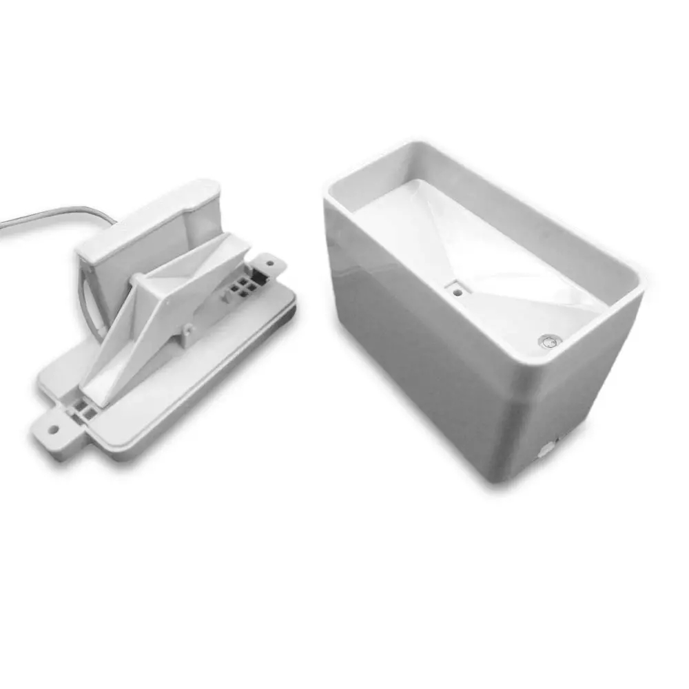
The 1/2" 2 way, 90 Degree, 2 port 12 V DC NPT Normally Closed Electric Solenoid Valve converts electrical signals to pneumatic functions as part of a larger system that allows users to interlock, isolate, and connect individual units of a larger operation.
DC 12V Electric Solenoid Valve 1/2 Inch Hose Magnetic Water Air Inlet Flow Switch
Specification:
| Material | Metal Plastic |
| Color | As per picture |
| Voltage | DC12V |
| Rated Power | 5W |
| Pressure | 0.02- 0.8Mpa |
| Interface Modes | 1/2'' Hose |
| Working Time | 5 hours at once (Max) |
| Insulation Class | E |
| Fluid Temperature | 0-90°C |
| Size | L*W*H/75*60*45mm/2.95*2.36*1.77'' |
| Inner diameter | 14mm/0.55'' |
| External diameter of thread | 20mm/0.78'' |
1 x Electric Solenoid Valve
Please note:
The actual valve size in the unit is smaller than the port size as you will find with most taps.

Basic 1 digit seven segment display can show numbers from 0-9 and a few characters. Consisting of seven LEDs (hence its name) arranged in a rectangular fashion. Each of the seven LEDs is called a segment because when illuminated the segment forms part of a numerical digit to be displayed.
Features
- Model: 5611BH Common Anode
- Size: 0.56 inch
- Colour: red
What's in the box?
1 x Red 7 Segment 0.56 Inch 1 Bit Common Anode LED Digital Tube
Resources
A few code examples
https://circuitdigest.com/microcontroller-projects/raspberry-pi-7-segment-display-tutorial
https://raspi.tv/2015/how-to-drive-a-7-segment-display-directly-on-raspberry-pi-in-python

GT2 timing belts are intended for lower load applications such as the first reduction in a gearbox, or motor to flywheel
GT2 Pulley
- Teeth: 20
- Groove width: 5mm
- Total width: 15mm
- Diameter of bore: 5mm
- Flange: Dual
- Material: Aluminium
GT2 Belt
- Pitch: GT2
- Width: 6mm
- Length: 2m
Idler pulley
- Teeth: 20
- Diameter of bore: 5mm
- Total width: 8mm
- Material: Aluminium
Features
- Durable and practical
- Designed specifically for linear motion
- GT2 Pulley and GT2 Belt are used together
- Round tooth profile guarantees that the belt tooth fits smoothly
- 20 Teeth contact with the belt minimizes the chance of the belt slipping
What's in the box?
1 x GT2 Belt
2 x GT2 Pulley
2 x Idler
4 x Tensioner
1 x Allen key

- Quick and economical.
- Straight through configuration.
- This coupler allows two ethernet cables with RJ45 connectors to be connected together so that the signal will pass straight through.
- It is a cheap and simple way to extend network cables and is ideal for moving networked computers without uprooting existing cables.
- Single Size: Approx.34x21x16mm
What's in the box?
1 x RJ45 Straight Through Ethernet LAN Cable coupler
Cables are not included

Resources
Wikipedia
espressif resources

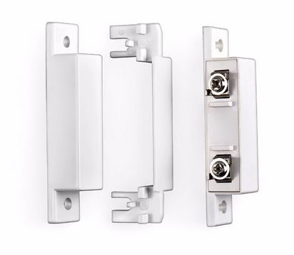
Description :
These door contact sensors are great for residential and hobby card access systems, as well as a security burglar alarm system. The door position switches operate with an internal magnetic reed switch that closes when the opposing magnet comes within range of the door sensor.
Hence when the door opens beyond the range point the door position switch will toggle from a closed signal to an open signal.
When this happens the access control system or alarm system will sense the change in continuity and will know that the door or window has been opened. When the door or window shuts, the door sensor will notify your security system that the opening has been closed.
Material Shield: Anti-fire ABS
Connecting Mode: N.C.
Rated Current: 100mA
Rated Voltage: (VDC)100
Operating Distance: More than 15mm, Less than 25mm
Rated Power: 3W
5 x KERUI Wired Door Switch