
Generic1


Specifications
- 0.8 mm diameter
- Net weight: 50g (appox.) net weight
- Rosin core
- 63% purity
- Great For Electronics and Electrical Wiring
What's in the box?
1 x solder roll
Resources
Introduction to soldering
Video: How to solder properly
The secrets to good soldering

The 10mm RGB LED Module is a compact and versatile lighting solution for a wide range of applications. With its small size and bright illumination, this LED module is perfect for creating eye-catching visual effects in electronics projects.
The module features three diodes in one module for red, green, and blue light, which can be mixed to create a wide range of colours using a microcontroller or other control system.
The module comes with pre-soldered 330 Ohm resistors making it easy to connect directly to your Raspberry Pi or other microcontrollers using 3.3V GPIO pins.
What's in the box?
1 x 10mm RGB LED Module

Also great for insulating the Hotend on your 3D printer.
Application:
- High temperature masking tape
- Frequency conversion power supply in the electronics industry. Also use as perfect heat resistance ribbon on 3d printing, powder coating, etc
- PCB protection during wave soldering
- Insulation on transformers, motors and coils
- Fiber Optic Cables
- Solar panels
Specifications
- 100% new and high quality
- Material: Polyimide
- Color: Brown Metallic
- Width: 5mm
- Length: 22 M
- Long term temperature: 260 ° C degrees
- Short term temperature: 300 ° c.
What's in the box?
1 x 5mm Kapton Tape

- Shape: Block
- Tolerance: ±1mm
- Material: NdFeB permanent Magnets
- Grade: N35
- Max Operating Temperature: 80 Celsius degree / 176 Fahrenheit degree
- Magnetization Direction: Axial
- Plating: Nickel+Copper+Nickel triple layer plated
What's in the box?
2 x Neodymium Magnets
Add an ear to your project with this well-designed electret microphone amplifier. This fully assembled and tested board comes with a 20-20KHz electret microphone soldered on. For the amplification, we use the Maxim MAX4466, an op-amp specifically designed for this delicate task! The amplifier has excellent power supply noise rejection, so this amplifier sounds really good and isn't nearly as noisy or scratchy as other mic amp breakouts we've tried!
This breakout is best used for projects such as voice changers, audio recording and audio-reactive projects that use FFT. On the back, we include a small trimmer pot to adjust the gain. You can set the gain from 25x to 125x. That's down to be about 200mVpp (for normal speaking volume about 6" away) which is good for attaching to something that expects 'line level' input without clipping, or up to about 1Vpp, ideal for reading from a microcontroller ADC. The output is rail-to-rail so if the sounds gets loud, the output can go up to 5Vpp!
What's in the box?
1 x GY-MAX4466 Electret Microphone Amplifier Module
Resources
Using it is simple
Connect GND to ground, VCC to 2.4-5VDC.
For the best performance, use the "quietest" supply available (on an for Arduino, this would be the 3.3V supply). The audio waveform will come out of the OUT pin. The output will have a DC bias of VCC/2 so when its perfectly quiet, the voltage will be a steady VCC/2 volts (it is DC coupled). If the audio equipment you're using requires AC coupled audio, place a 100uF capacitor between the output pin and the input of your device. If you're connecting to an audio amplifier that has differential inputs or includes decoupling capacitors, the 100uF cap is not required. The output pin is not designed to drive speakers or anything but the smallest in-ear headphones- you'll need an audio amplifier (such as 3.7W stereo amp) if you want to connect the amp directly to speakers. If you're connecting to a microcontroller pin, you don't need an amplifier or decoupling capacitor - connect the OUT pin directly to the microcontroller ADC pin. For audio-reactive projects, we suggest using an FFT driver library which can take the audio input and 'translate' it into frequencies.

High quality anti-static wrist strap with grounding lead and clip to prevent ESD damage to sensitive electronic components or equipment. The wrist strap with alligator clip tip is fully adjustable. The inner conducting layer is made of stainless steel filaments. The lead is made from durable polyurethane coated coil cords.
Specifications
- High quality strain relief
- Soft elastic band for comfort
- Current limiting resistor 1M Ohm ± 5%
- Electro-scattering time 0.1sec
- Rinse resistant
- Weight: 25g
- Cable Length: 180cm
What's in the box?
1 x Anti-static wrist band with 180cm grounding lead

3D printing plastics often have low yield strength and cannot reliably produce threaded features. Embedded metal nuts provide stronger and more precise threading for hidden fasteners. The nut melts and reflows the plastic around it, enhancing its strength. However, there are design constraints - the nut must be on a part face and cannot be reinforced beyond the plastic's properties.
Specifications
- Thread Size: M3
- Height: 4mm
- Outer Diameter: 5mm
- Material: Brass
What's in the box?
1 x Brass Heat Threaded Inserts Embedment Nut

Specifications
- Module Type: Buck converter
- Input: 8V to 90V
- Output: 5V
- Output current: 5A(max)
- Conversion efficiency: up to 96%
- Size: 46mm x 32mm x 18mm
1 x 5V 5A Power Adapter

Product size: 35.5 * 17 * 8.3 mm
Input voltage range: 6 to 26 v
Output voltage: 5.2 V (consider charging line loss, output is about 5.2 V, the load end is around 5 V)
Limit the output current: 3 a (in the absence of radiator, stable output current limit is 2 a)
Note 1: is the cathode can't meet the, and the input voltage can't more than 26 v, otherwise it will result in the chip damage!
Note 2: in current work, not touch on the circuit board sampling resistor, IC, or may result in output voltage mutation damage equipment!
What's in the box?
1 x 9V 12V 24V to 5V 3A USB step-down voltage regulator module DC-DC Converter

What's in the box?
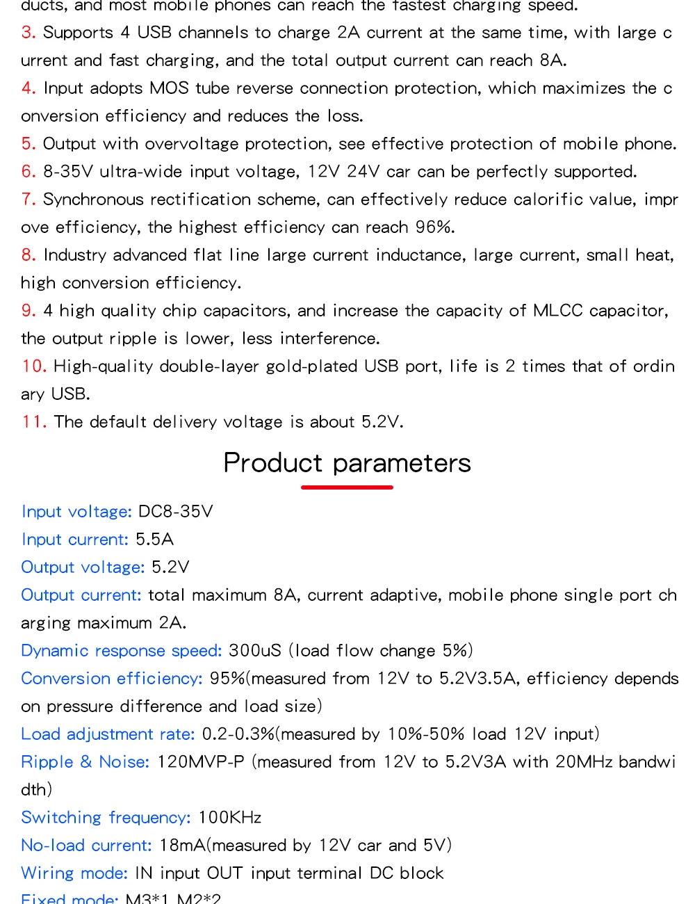
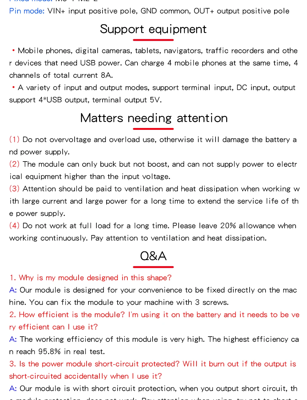
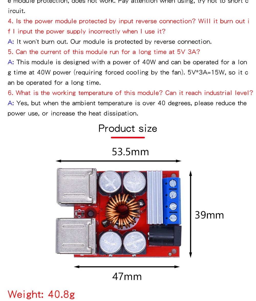
1 x DC-DC Vehicle Charging Board 8V-35V to 5V 8A Power Supply Depressurization Module 4 port USB Output mobile Charger