
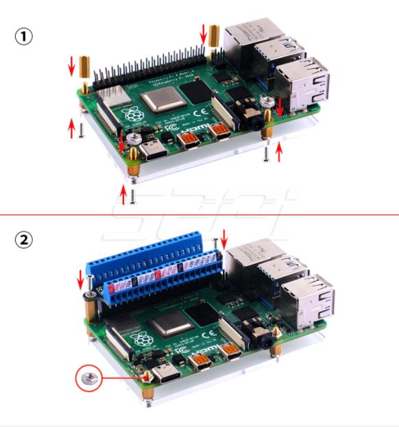
Generic1


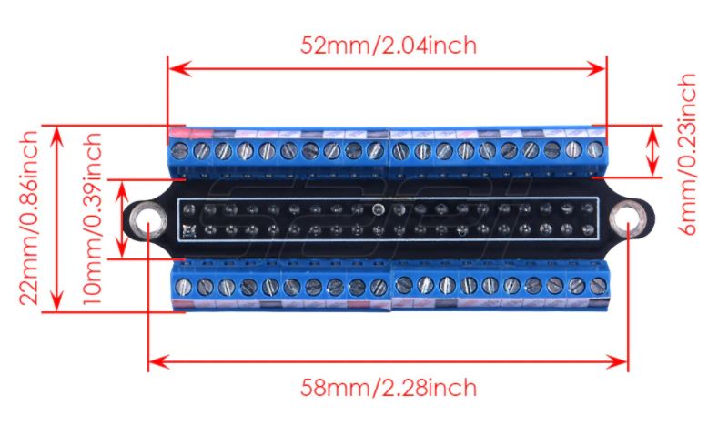
- Tiny size & solidly built
- Well made terminal block
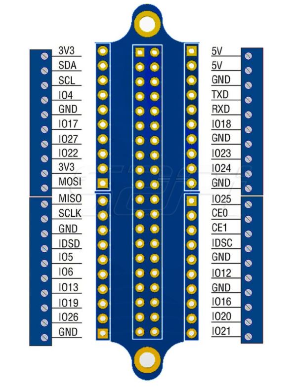
- Legible miniscule printing of the labels of each of the GPIO pin's function
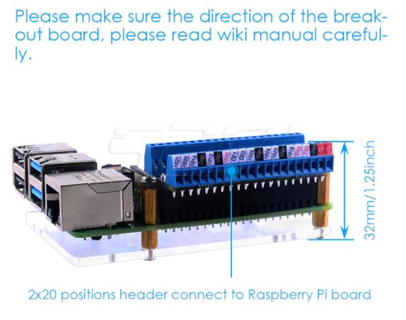
- Secure connection to the Raspberry Pi
What's in the box?
1 x Terminal block
1 x Screwdriver
1 x Acrylic board
2 x Nuts
2 x M2.5x11 brass standoffs
4 x M2.5x5 6 brass standoffs
6 x Screws
Resources
Wiki - Raspberry Pi GPIO Terminal Board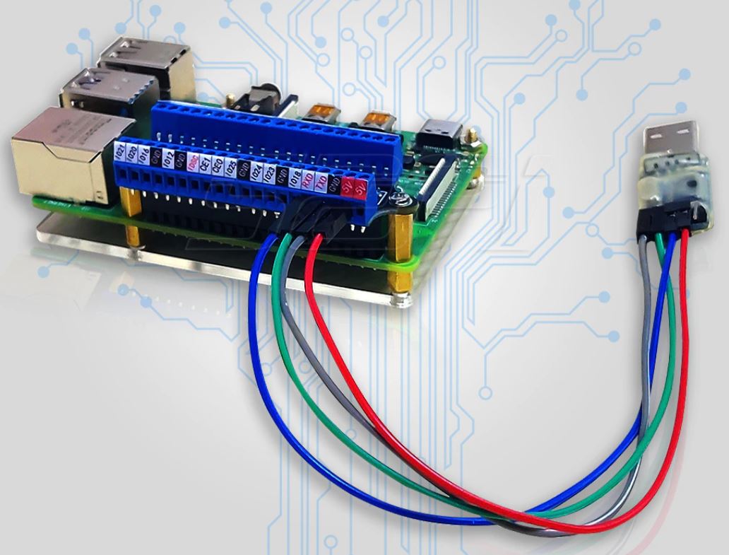
(* Raspberry Pi NOT included - ONLY GPIO screw terminal*)
(* Raspberry Pi NOT included - ONLY GPIO screw terminal*)

Specifications
- HDMI
- 1080p
- female to female
- black
- extension adapter
What's in the box?
1 x hdmi adapter

Heat-shrink tubing is a shrinkable plastic tube used to insulate wires, providing abrasion resistance and environmental protection for stranded and solid wire conductors, connections, joints and terminals in electrical work.
Specifications:
Shrinkage Ratio: 2:1 (will maximum shrink to 1/2 its supplied diameter)
Cutting method: Scissors or sharp knife
What's in the box?
1 x 1m heat shrink tube
Heat-shrink tubing is a shrinkable plastic tube used to insulate wires, providing abrasion resistance and environmental protection for stranded and solid wire conductors, connections, joints and terminals in electrical work.
Specifications
Shrinkage Ratio: 2:1 (will maximum shrink to 1/2 its supplied diameter)
Cutting method: Scissors or sharp knife
What's in the box?
1 x 1m heat shrink tube

Ring terminals connect two or more wires to a single connection point, by fitting the open face of the terminal over a stud. They create a solid connection as the ring that is fitted over the stud cannot come loose or fall off. This removes the possibility of the ring terminal disconnecting. They are widely known for the semi-permanent connections that they create. To make ring terminals even better, they can easily be used with two or more wires depending on the application. Ring terminals are the most secure type of tongue style terminal available and are commonly chosen for their durability, ease of use, and longevity in tough conditions.
Specifications
- Conductor cross section: 0.5-1.5 mm2
- Bolthole: 4mm
What's in the box?
1 x pack of 10 lugs
You will find our lugs selection here

Female Spade lugs provide a quick and reliable solderless electrical connection. These single conductor connectors are made to connect with a predefined connector size or male quick connects.
Specifications
Conductor cross section: 0.5-1.5 mm2
What's in the box?
1 x pack of 10 lugs
You will find our lugs selection here

Ring terminals connect two or more wires to a single connection point, by fitting the open face of the terminal over a stud. They create a solid connection as the ring that is fitted over the stud cannot come loose or fall off. This removes the possibility of the ring terminal disconnecting. They are widely known for the semi-permanent connections that they create. To make ring terminals even better, they can easily be used with two or more wires depending on the application. Ring terminals are the most secure type of tongue style terminal available and are commonly chosen for their durability, ease of use, and longevity in tough conditions.
Specifications
- Conductor cross section: 1.5-2.0mm2
- Bolthole diameter: 4mm
What's in the box?
1 x pack of 10 lugs
You will find our lugs selection here

Fork Terminals are a type of connector used to attach a wire or wires to a stud, bus bar, or another part of an electrical system.
These Lugs are insulated to ensure safe and secure connections to an electrical device.
Specifications
- Conductor cross section: 1.5-2.5 mm2
- Bolthole diameter: 4mm
What's in the box?
1 x pack of 10 lugs
You will find our lugs selection here

Joiner Terminals are a type of connector used to attach a wire or wires to a stud, bus bar, or another part of an electrical system.
These Lugs are insulated to ensure safe and secure connections to an electrical device.
Specifications
Conductor cross section: 1.5-2.5 mm2
What's in the box?
1 x pack of 10 lugs
You will find our lugs selection here

Specifications
- Voltage: DC 5V
- Colour: RGB
- Outer radius of 2 x 28mm
- Inner radius of 2 x 8mm
Please note: Soldering will be required to connect your wires
What's in the box?
1 x 8 Bit WS2812 5050 RGB LED Driver Development Board

Specifications
- Brand: CHANZON
- Lens Size: 5mm Diameter
- Lens: Colour Lens
- Emitting Colour: Green Flash
- Viewing Angle: 20 Degree (Colour Lens)
- Forward Voltage: 3.0-3.2V
- Current: 20mA
- Frequency: 1.5HZ
- Flicker Frequency: 90 Times / Minutes
- Polarity: Anode (Longer Leg) | Cathode (Shorter Leg)
What's in the box?
10 x Flashing LEDs

Specifications
- Brand: CHANZON
- Lens Size: 5mm Diameter
- Lens: Colour Lens
- Emitting Colour: Red Flash
- Viewing Angle: 20 Degree (Colour Lens)
- Forward Voltage: 3.0-3.2V
- Current: 20mA
- Frequency: 1.5HZ
- Flicker Frequency: 90 Times / Minutes
- Polarity: Anode (Longer Leg) | Cathode (Shorter Leg)
What's in the box?
10 x Flashing LEDs

The LM35-series devices are precision integrated-circuit temperature sensors, with an output voltage linearly proportional to the Centigrade temperature. The LM35 device has an advantage over linear temperature sensors calibrated in Kelvin, as the user is not required to subtract a large constant voltage from the output to obtain convenient Centigrade scaling. The LM35 device does not require any external calibration or trimming to provide typical accuracies of ± ¼ °C at room temperature and ± ¾ °C over a full −55°C to 150°C temperature range. Lower cost is assured by trimming and calibration at the wafer level. The low output impedance, linear output, and precise inherent calibration of the LM35 device makes interfacing to readout or control circuitry especially easy. The device is used with single power supplies, or with plus and minus supplies. As the LM35 device draws only 60 μA from the supply, it has very low self-heating of less than 0.1°C in still air. The LM35 device is rated to operate over a −55°C to 150°C temperature range
Features
• Calibrated Directly in Celsius (Centigrade)
• Linear 10-mV/°C Scale Factor
• 0.5°C Ensured Accuracy (at 25°C)
• Rated for Full −55°C to 150°C Range
• Suitable for Remote Applications
• Low-Cost Due to Wafer-Level Trimming
• Operates From 4 V to 30 V
• Less Than 60-μA Current Drain
• Low Self-Heating, 0.08°C in Still Air
• Non-Linearity Only ±¼°C Typical
• Low-Impedance Output, 0.1 Ω for 1-mA Load
Applications
• Power Supplies
• Battery Management
• HVAC
• Appliances
What's in the box?
1 x LM35DZ temperature sensor

This module is the perfect starting point if you are looking to build your own power bank.
This module is ideal for 18650 batteries, 65mm long with the flat top. In the event that you use:
- old batteries
- different capacities
- differnet brands
Please ensure that they are at least above 3.5V each
Not ideal to be used on batteries that have been too far depleted.
After the battery is installed, plug in the charger to activate the battery before use.
The real world conversion rate of a new "real capacity" battery is about 80%. Because there is a line loss of the connection line. Estimation of mixed batteries or "budget" batteries are near impossible to estimate.
For peak use, first allow the battery to fully discharge before charging it.
Note: Reversing the polarity of the battery will burn the module.
Specifications
- Switch Charging
- Internal 2A charging current
- Charging efficiency up to 90% @ 2A
- Charging swtch frwquency 1MHz
- Trickle/constant current/constant voltage three-stage charging
- Charging current Adaptive adapter function
- Charging current Temperature adjustment function, charging current automatically decreases with the increase of temperature
- C/10 charging terminates
- Intergrated charge overvoltage protection and battery overtemperature protection
- Synchronous boost output 5.1V
- Discharge switch frequency 50OKHz
- Discharge efficiency up to 94%
- Automatic identifiation of load, load automatically shut off
- Original boost output heat regulation function
- Protection of over current, short circuit, over voltage and over tepmperature of discharge module
- Long press the switch, wake up the motherboard, charge the charging time of the phone, press the switch, the output can be turned off, the motherboards stops working.
- MaIn board size: Thickness 9 * Width 25 * length 67 mm
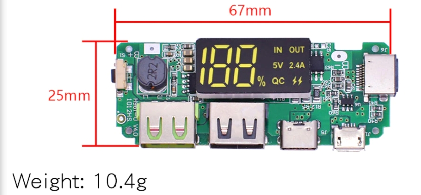
What's in the box?
1 x Power bank type charging module

Original 0.4mm Copper M6 Thread Extruder Nozzle For Ender-3 CR-10 V2 CR-10S Pro Ender-5 CP-01 CREATITY 3D
Specifications
1. Material: Copper
2. Size: 13mm x 6mm
3. Weight: 2g
4. Nozzle thread: M6
5. Nozzle accuracy: 0.4mm
What's in the box?
1 x 0.4mm Nozzle
Short antenna for Transmitter
Long antenna for Receiver
About the transmitter module (square shape)
- Model: WL102-341
- Material: Plastic Metal
- Colour: shown as pictures
- Size: 16×12×1mm
- Operating frequency: 433.92 MHz
- Mains input voltage range: 2.0V-3.6V
- Shutdown mode current is less than 1uA
- Transfer rate: up to 20KHz
- Launch distance: 20-100 meters
- External antenna: 25cm ordinary multi-core or single-core line
- Temperature range: -45℃~85℃
About receiver module (rectangular shape)
- Model: RX470-4 (RX470-4 is WL101-341 upgraded version, more stable performance, faster data transfer)
- Material: Plastic Metal
- Colour: shown as pictures
- Size: 30×9×1mm
- Operating frequency: 433.92 MHz
- Mains input voltage range: 2.2V-5V
- Working current: Type: 2.1mA (Requirement:VDD=5V) ; Type: 2.1mA (Requirement:VDD=3V)
- Quiescent Current: 1uA
- Temperature range: -40℃~85℃
- External antenna: 32cm single core wire, wound into a spiral
What's in the box?
1 x 433MHz RF transmitter module
1 x 433MHz RF receiver module
2 x 433MHz spring antennas (Short antenna for Transmitter; long antenna for Receiver.)
Resources
Configure and read a 433Mhz RF Transmitter With Receiver on the Raspberry Pi

GRBL 0.9 compatible
4-Axis support (X, Y, Z, A-Can duplicate X, Y, Z or do a full 4th axis with custom firmware using pins D12 and D13)
2 x End stops for each axis
Coolant enable
Compatible with A4988 or DRV8825 stepper driver
Working Voltage: 12-36V DC
Max. Working Current: 2.5A
RAMPS 1.4
Mechanical Switch Endstop
Red: VCC (ramps )
Black: GND (ramps -)
Green: SIGNAL (ramps s)
DRV8825 Stepper Motor Driver
Size: 1.5mm x 2mm
Upgraded from A4988
Maximum Current: 2.5A
32 Subdivision: 1, 1/2, 1/4, 1/8, 1/16, 1/32
4-layer PCB board for better heat dissipation
Suitable for driving stepper motors up to 8.2V~45V, 2.5A
Nema 17 Stepper Motor
Model: 17HD48002H-22B
Rated Current/phase: 1.7A
Step Angle: 1.8 deg.
Holding Torque: 59Ncm(84 oz.in)
Frame Size: 41 x 41mm
Body Length: 47mm
Shaft Diameter: 5mm
Shaft Length: 22mm
Latest CH340G CNC Shield expansion board Version 3.0 for Arduino, and compatible for GRBL 0.9.
UNO R3 Board
MCU: ATmega328
USB interface: ATmega16U2 cable with USB .
This is a professional sensor kit for UNO R3. New and upgraded, we provides various components or sensor module, with which you will find it easy for you to complete every experiments or learning. All these are packaged in a portable case, easy to carry and storage.
What's in the box?
1 x CNC Shield V3
1 x UNO R3 MEGA328P CH340G with USB Cable
5 x DRV8825 Stepper Motor Driver with Heat Sink
5 x RAMPS 1.4 Mechanical Switch Endstop
5 x 3pin Cable (70cm)
3 x Nema 17 Stepper Motor
3 x Nema 17 Mounting Bracket

This useful kit is very handy for your electronic projects or repairs.
Features
- Structure: Fixed capacitors
- Type: Aluminum Electrolytic Capacitors
- Rating: 0.22uF~ 470uF
- Voltage: 16-50V
- Colour: Black
- Quantity: 120PCS
What's in the box?
10 x 50V 0.22μF ±20% 105°C Φ 4 x 7 mm
10 x 50V 0.47μF ±20% 105°C Φ 4 x 7 mm
10 x 50V 1 μF ±20% 105°C Φ 4 x 7 mm
10 x 50V 2.2μF ±20% 105°C Φ 4 x 7 mm
10 x 50V 4.7μF ±20% 105°C Φ 4 x 7 mm
10 x 50V 10μF ±20% 105°C Φ 4 x 7 mm
10 x 50V 22μF ±20% 105°C Φ 4 x 7 mm
10 x 16V 33μF ±20% 105°C Φ 4 x 7 mm
10 x 16V 47μF ±20% 105°C Φ 4 x 7 mm
10 x 16V 100μF ±20% 105°C Φ 5 x 7 mm
10 x 16V 220μF ±20% 105°C Φ 5 x 7 mm
10 x 16V 470μF ±20% 105°C Φ 6 x 7 mm
Resources
Theory
Introduction
Types

Although the reader does not read the information on the NFC card, it is triggered by a 13.56 Mhz NFC card
Working frequency: high/low frequency card
Working voltage: 50/60Hz 160-260VAC
Maximum load current: 40A
Maximum load power: 8800W
Static working power: 1W
Delayed power-off time: 10-20 seconds
Not working state: the indicator light is red or blue
Service life: When the relay contacts are at 220V full load, the service life is more than 100,000 times
Working temperature:-20℃-- 60℃
Working humidity: 50 ℃ 10-95%RH
Dimensions: 86mm x 86mm x 40mm
Shell material: flame retardant PC plastic
Shell color: White