
Special Offers


The 28BYJ-48 motor runs in full step mode, each step corresponds to a rotation of 11.25°. That means there are 32 steps per revolution (360°/11.25° = 32). In addition, the motor has a 1/64 reduction gear set.
The power consumption of the motor is around 240mA.
The ULN2003 is one of the most common motor driver ICs, consisting of an array of 7 Darlington transistor pairs, each pair is capable of driving loads of up to 500mA and 50V. Four out of seven pairs are used on this board.
The board has four LEDs that show activity on the four control input lines (to indicate stepping state). They provide a nice visual when stepping.
The board also comes with an ON/OFF jumper to isolate power to the stepper Motor.
Specifications
- High quality stepper motor with ULN2003 driver
- Suitable for microcontroller development
- Voltage: DC 5V
- Diameter: 28mm
- Step Angle: 5.625 x 1/64
- Reduction Ratio: 1/64
- Dimensions: 1.38 in x 1.18 in x 0.39 in (3.5 cm x 3.0 cm x 1.0 cm)
- Weight: 1.45 oz (41 g)
What's in the box?
1 x stepper motor
1 x ULN2003 driver
Resources
How to control a ULN2003 stepper motor with Raspberry Pi

Arduino Mega is an ATmega2560 core microcontroller development board. Itself has 54 digital input/output terminals (14 PWM outputs), 16 simulation inputs, 4 UARTs (hardware serial ports), using the 16 MHz crystal oscillator. With the bootloader, download the program directly via USB without having to go through other external writers. Supply part of the optional USB power, or external power using a AC-to-DC adapter and battery.
Rapid growth due to open original code, as well as the concept of using Java (cross-platform) C language development environment for Arduino module. The Arduino can easily use the Arduino language with Flash or Processing ... software communication, to make multimedia interactive works. Arduino development IDE interface is based on open-source principles, allows you to download for use in projects.
Power supply design
There are two options for the power supply system of the Arduino Mega. USB direct power supply or external power supply. The power supply will be switched automatically. External supply AC-to-DC adapter or the battery can be selected on this control panel. Limit the voltage range of 6V ~~ 12V, but if the voltage supplied is less than 6V, I / O port may not be supplied to a voltage of 5V, and therefore not stable; If the voltage is greater than 12V, the regulator device may possibly overheat and damage the Arduino MEGA. It is therefore recommended that for the operating supply of 6.5 ~ 12V, the recommended power supply is 7.5V or 9V.
The development board have been rigorously tested at the factory.
Specifications
- Microcontroller: ATmega2560
- Operating voltage: 5V
- Input voltage (recommended): 7-12V
- Digital I/O pins: 54 (of which 14 provide PWM output)
- Analog input pins: 16
- DC current per I/O pin: 40 mA
- DC current for 3.3V Pin: 50 mA
- Flash Memory: 256 KB of which 4 KB is used by the bootloader
- SRAM: 8 KB
- EEPROM: 4 KB
- Clock Speed: 16MHz
What's in the box?
1 x Control board
1 x USB cable
Resources
Getting started with Arduino products

- Joystick Size: Approx. 95x60x100mm
- Encoder Board Size: Approx. 85x35mm
- USB Cable Length: Approx. 1.8m
- Colour: Red
We have tested this unit on Raspberry Pi using Retropie and a Windows 7 PC using MAME.
What's in the box?
1 x Encoder Board
1 x USB Cable
1 x 5 pin Cable for Joystick
1 x 5 Pin Joystick
8 x 30mm Push Buttons
2 x 24mm Push Buttons
10 x Cables for Buttons
Resources
Get Retropie on the Raspberry Pi
ModMyPi setup guide
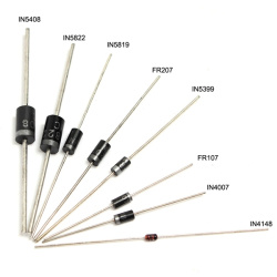
2 pin through hole rectifier diodes used for electronic projects, hobbies and repairs. Used in radios, power supplies and other devices.
- Wattage: 1W
- Diode/rectifier type: DO-41
- RoHS: Yes
- Standard Recovery Power Rectifier
- Repetitive Reverse Voltage Max, Vrrm: 50V
- Forward Current Avg Rectified, IF(AV): 1A
- Forward Surge Current Max, Ifsm: 30A
- Forward Voltage Max, VF: 1.1V
- Current Rating: 1A
- Mode: IN5822, IN5408, IN5399, FR207, FR107, IN5819, IN4007, IN4148
Resources
Intoduction
Basics, Types, Characteristics, Applications & Packages

Hack this component to form part of your weather station.
Specifications
| Sensor | 3-cup anemometer |
| Measurement Description | Wind speed |
| Range | 0 to 45 m/s (0 to 100 mph) |
| Starting Threshold | 0.45 m/s (1.0 mph) |
| Accuracy | 0.11 m/s (0.25 mph) or 1.5% |
| Contact Rating | 10 mA (maximum) |
| Operating Temperature Range | -50° to 70°C |
| Distance Constant |
|
| Cable Description | Quick-connect connector with vinyl jacketed, shielded cable |
What's in the box?
1 x Anemometer
Resources

It's easy to set up, features a great resolution, comes complete with a black acrylic stand, and has touch by default!
Recent upgrades
If you were used to seeing the Self Test at power on, this has now been removed. However if you remove the jumper located on the controller board you can re-enable this feature.
This device uses the Pi's HDMI output for display, and the Pi's USB port for touch control. Assembly of the Waveshare 10.1" screen is easy, just follow this simple guide here.
Please Note. This device does require some simple set up. You will need attach the EU fitting to the power adapter.
The LCD Screen Features
- 10.1inch HDMI LCD (B)
- 1280x800 Resolution
- UK 5V 2A Power Supply Included
- Capacitive touch control
- Supports Raspberry Pi, Ubuntu, Windows 10 IoT driver free
- Can also be used as a computer monitor, supports Windows 10/8.1/8/7/XP etc.
- Supports BB Black, comes with Angstrom image
- HDMI interface for displaying, USB interface for touch control
- Input interfaces: HDMI
- Multi languages OSD menu, for power management, brightness/contrast adjustment, etc.
- Firmware is upgradable to support more new features (continually updated)
The Case Features
- Material : High quality black and clear Acrylic
- Comes with bottom holder, 45° tilt angle
- Features mounting holes for Raspberry Pi 3B/2B/B /A /B, and BB Black
What's in the box?
1 x HDMI 10.1" Touch Screen
1 x Acrylic panels
1 x HDMI cable
Resources
User Manual
Quick Assembly Guide
Wiki

Specifications
- Colour: Silver Black
- Material: Metal, Glass
- Diameter: 60mm
- Size: about 154mm x 100mm x 125mm

Keep all kinds of cord-cables well organized and tidy in place, used to tie up speaker cables, guitar cables, TV cables, microphone mic, computer cables, and much more.
Can write directly onto the tag, help you know which cable is headed where and remember which cable is which.
Using a sharpie to Write make a perfect combination to ending cable madness! can use them in the garden, office, garage, workshop, around the house and more.
Specifications
- Material: nylon
- Colour: white
- Cable Size: 100mm x 3mm(L*W)
- Tag Size: 20mm x 13mm(L*W)
- Quantity: 50pcs
Features
- Nylon cable tie label
- Made from high quality nylon 66 material, UL recognized
- Durable,acid-resistance, anti-rust,anti-aging,insulating
- Unique marking tag design, enable you to mark the different cables when connected, easy to recognize.
- Widely used in bundled cables for TV, computer, appliances, lighting, electrical, electronic toys and other products lines
What's in the box?
50 x Nylon Zip Cable Tie Labels

Please note: You will need to buy a different CSI cable for use with RPi 5 or ZERO.
Raspberry Pi IR-CUT Night Vision Camera plugs directly into the CSI connector on the Raspberry Pi, and features two high-intensity Infrared LED spotlights for night time recording!
Features
- Raspberry Pi Camera, supports all revisions of the Pi
- Embedded removable IR-CUT filter, eliminating color distortion in the daylight
- Comes with infrared LED, supports night vision
- 5 megapixel OV5647 sensor
- Adjustable focus distance
- Camera specifications
- CCD size : 1/4inch
- Aperture (F) : 1.8
- Focal Length : 3.6mm
- Angle of View (diagonal) : 75.7 degree
- Sensor best resolution : 1080p
- 4 screw holes
- Used for attachment
- Provides 3.3V power output
- Supports connecting infrared LED and/or fill flash LED
- Dimension: 31mm × 32mm
The new Raspberry Pi OS release includes the new Picamera2 Python camera interface.
What's in the box?
1 x Camera
Resources

The Adafruit 4-Channel I2C 12-Bit ADC is a high-precision ADC and features the ADS1015 chip, which provides 12-bit precision at 3300 samples/second over I2C. The chip can be configured as 4 single-ended input channels, or two differential channels. As a nice bonus, it even includes a programmable gain amplifier,with up to x16, to help boost smaller single/differential signals to the full range. We like this ADC because it can run from 2V to 5V power/logic, can measure a large range of signals and its super easy to use. It is a great general purpose 12 bit converter.
- Wide Supply Range: 2.0V to 5.5V
- Low Current Consumption: Continuous Mode: Only 150µA Single-Shot Mode: Auto Shut-Down
- Programmable Data Rate: 128SPS to 3.3kSPS
- Internal Low-Drift Voltage Reference
- Internal Oscillator
- Internal PGA
- I2C Interface: Pin-Selectable Addresses
- Can run from 2V to 5V power/logic
- Measures a large range of signals and is super easy to use.
- 12-bit precision at 3300 samples/second over I2C.
- Configurable as 4 single-ended input channels, or two differential channels.
- Includes a programmable gain amplifier, up to x16, to help boost up smaller single/differential signals to the full range.
- Breakout Board equipped with ferrites to keep the AVDD and AGND quiet
What's in the box?
1 x Adafruit 12-Bit ADC
Tutorials

The Official Raspberry Pi Zero & Zero Wireless Case is now available! Specially made and beautifully crafted in red & white, this nifty and tactile snap-together case is designed to protect your Zero!
The case comes with three swappable lids, each with a different function:
- Raspberry Pi Camera lens holder lid with included extra short 35mm Raspberry Pi Zero camera cable(This cover is for the normal Raspberry Pi camera. The zero camera lens is to small to fit snugly.)
- GPIO access lid, with GPIO hole for all your hacking needs
- Solid lid, for those who want an all around protected Zero!
The Official Raspberry Pi Zero Red & White Case Features:
- Fabulous Raspberry Red and White Colour Combination
- 2 Part "Snap-Fit" Enclousure, with 3 separate lids (GPIO/Camera/Solid)
- Underside slot for GPIO access
- Cut-outs for all connection points
- No SD card access (keeps your card protected!)
- Included 4 x Stick on rubber feet for case stability
Please note:
Some mini-HDMI cables will need to have their shroud's cut down to fit the official case.
What's in the box?
1 x Raspberry Pi Zero Red & White Case bottom part
3 x swappable lids
1 x Zero camera adapter ribbon
4 x Stick on rubber feet

58mm long by 44mm wide - adds a splash of colour to laptops, camera cases, fridge doors or anywhere else you can think to put it.
Not only are you helping the Foundations educational aims by buying these, you're also brightening up the world for everyone else :-)
What's in the box?
6 x Raspberry Pi Stickers

The hole gap is 2.54mm, and it's compatible with IC with DIP package.
The IO port can be quickly and easily implement your ideas.
Note:
- Extra header spacer included
- 170 tie points breadboard arranged in 34 rows of 5 pins included
Package includes:
1 x Prototyping Shield kit

Power supply for dc projects.
With DC05 power supply jack
Cable Length: 12cm
Specifications:
- Voltage: 9V
- Material: Plastic
- Power: 6 x 1.5V AA batteries
- Color: Black
- Net weight: 25g
What's in the box?
1x Battery case with DC2.1 power jack
Need batteries? You will find our battery selection here

If you love to power your projects with convenient 5V USB, then this DC-DC Step-Down Buck Module with Dual USB 5V 3A Output is an ideal choice!
Dual USB Output Buck Power Supply Adapter For Car Auto Cellphone MP3 and much more!
Specifications
- Model:usb1002
- Name: Power Module
- Features: Buck Charge
- Product size: 33mm x 33mm x 8mm
- Input voltage range: 6-24V
- Output voltage: 5.2V (the output terminal is 5.3-5.4V, the load side is 5.1-5.2V)
- Output Current: 3A (without heat sink, the stability of the output current is 2A)
Important Notes
- The input voltage can not exceed 24V, otherwise it will cause damage to the device!
- The input positive and negative can not be reversed, otherwise it will cause damage to the device!
- You will only be able to make use of the 3A current rating at higher input voltages!
What's in the box?
1 x Dual USB Power Module

Infrared receiving module adopts 1838 infrared receiving head
Light resistance, strong electromagnetic interference, built-in infrared dedicated IC, can work under 500 lux light intensity
Widely used in remote control toys, satellite receivers, air conditioner, heater, electric fan, lighting and other home appliances.
Specifications:
Dimension: 6.4 x 7.4 x 5.1mm
Receiving angle: 90 °
Working voltage: 2.7 ~ 5.5V
Frequency: 37.9KHz
Receiving range: 18m
Package includes:
1 x Infrared sensor receiver module
Resources:
Wiki
Need to log loads of sensor data on your Arduino? Temperature, humidity, air pressure, access control.....This is the shield you'll need.
Specifications
| Model | XD-05 Arduino |
| Color | Blue |
| Material | CCL |
| Features | XD-05 Arduino |
| Specification |
|
| Application | Arduino data logging shield |
| Packing List | 1 x XD-05 arduino data logging shield |
What's in the Box?
1 x Data Logging Shield
Resources:
Instructables

- Great for electronic projects and kits.
- Perfect use for home, office and industry electrical equipment and electrical appliances
- Size: 10mm
- Voltage: 1.8V ~ 2.2V for Red & Yellow, 3.0V ~ 3.4V for Blue, Green & White
- Current: 20 mA
- Luminous Intensity: 5000 MCD
- Colour: RED, BLUE, YELLOW, GREEN, WHITE
- Lens Color : Diffused
| 10Pcs Five Colors 10mm Round Bright Light LED Assortment Kit | ||||
| Color | Size | Current(mA) | Lens Color | Quantity |
| Red | 10mm | 20 | red | 2Pcs |
| White | 10mm | 20 | white | 2Pcs |
| Yellow | 10mm | 20 | yellow | 2Pcs |
| Green | 10mm | 20 | green | 2Pcs |
| Blue | 10mm | 20 | blue | 2Pcs |
Resources
Python library
Introduction

Description:
ATmega328 is commonly used in many projects and autonomous systems where a simple, low-powered, low-cost micro-controller is needed.
The Arduino Compatible Nano V3 development board is a microcontroller board based on the Arduino Nano
Specifications:
- Microcontroller Atmel ATmega328
- Operating Voltage (logic level): 5V
- Input Voltage (recommended): 7V ~ 12V
- Input Voltage (limits): 6V ~ 20 V
- Digital I/O Pins: 14 (of which 6 provide PWM output)
- Analog Input Pins: 8
- DC Current per I/O Pin: 40mA
- Flash Memory: 32KB (ATmega328) (of which 2 KB used by bootloader)
- SRAM: 2KB (ATmega328)
- EEPROM: 1KB (ATmega328)
- Clock Speed: 16MHz
1 x Arduino Compatible Improved Version Nano V3.0 with headers pre-soldered
1 x USB cable
Resources:
Getting started with Arduino products
This pre-built Edge Connector Breakout Board for the micro:bit gives access to all the important pins on the bottom edge of the micro:bit.
Looking to do more with your micro:bit? Unlock its potential with this pre-built version of our Edge Connector Breakout Board! This breakout board has been designed to offer an easy way to connect additional circuits and hardware to the pins on the edge of the micro:bit. It provides access to all of the micro:bit processor pins allowing a lot of extra functionality to be added. The datasheet (below) includes a helpful diagram explaining the function of every pin on the micro:bit.
This Edge Connector Breakout Board for the micro:bit gives access to all of the important pins on the bottom edge of the micro:bit. 21 pins are broken out in total; providing additional I/O lines, direct access to buttons A and B, the LED matrix outputs and the I2C bus. Please refer to the datasheet below for more details.
The micro:bit pins are broken out to a row of pin headers. These provide an easy way of connecting circuits using jumper wires. The SCL and SDA pins are separated at the edge of the board (solder pads) providing easy identification. The PCB includes a prototyping area with 3V, 0V and unconnected rows that can be soldered to. This allows the easy connection of switches, sensors and any pull-up or pull-down resistors etc. as required.
To use the breakout board the micro:bit should be inserted firmly into the connector as shown below: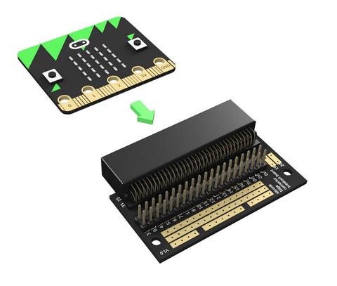
Note:
- This product is supplied with straight double row PCB pin headers already soldered to the breakout board
Features:
- Features a dedicated pin strip for quick and easy prototyping
- Breaks out 21 pins from the edge of the micro:bit
- Dedicated prototyping area with 3V and 0V rows
- Labelled pins and clear, straightforward documentation
Contents:
- 1 x Edge Connector Breakout Board for the micro:bit, pre-built
Dimensions:
- Length: 60mm
- Width: 40mm
- Height: 11.8mm
Video available at https://youtu.be/bzm4zepbGAc
Requires:
- 1 x micro:bit
Resources: