Special Offers


Specifications
- Frequency Range: 30Hz~15000Hz
- Impedance: 2.2K Ohm
- Sensitivity: -52dB±5dB
- Plug: 3.5mm
- Length of cable: Approx 2m
- Net weight: 11g
- Colour: Black
What's in the box?
1 x 3.5mm Clip Microphone

you can turn off the LED and light from any point in time.
To use this feature, simply link your eWeLink application to Amazon Alexa. With a few steps you can tell Alexa or turn off lights and turn on all devices.
Remote ON/OFF
Scheduled/countdown timing
One-key sharing
Group/scene management
Specifications:
Terminal platform: Android , IOS
Connection: wifi
Control distance: Infinity (in 2G / 3G / 4G / WIFI network)
Standard: 86 type EU / 120 type US
Wireless power consumption: <0.3w
System: support IOS6.0 / Android2.3 and above
Input Voltage: AC90 ~ 250V, 50 / 60hz
Max. Current: 2A
Rated power: 400W
Wifi Frequency: 2.4GHz 802.11b / g / h
Power supply: zero fire power supply
Shell material: flame retardant ABS
Panel material: tempered glass
Color: White
Size:
120 type: 120mm x 78mm x 41mm
Package Includes:
1 x Touch Wifi Switch Module

This kit includes the sensor parts to build your own DIY weather station
What's in the box?
- 1 x Wind direction sensor
- 1 x Wind speed sensor
- 1 x Rain gauge sensor
- 1 x Mast 570mm
- 1 x Top double arm bracket
- 2 x Side single arm brackets
- cable ties
- clamps
- solar RF sender
Have a look at the Rasberry Pi Foundation weather project for a wired solution to use these sensors:
https://projects.raspberrypi.org/en/projects/build-your-own-weather-station
For the brave there is a discussion on sniffing the signal from the RF sender:
https://www.raspberrypi.org/forums/viewtopic.php?t=96780
And some good reading at https://rayshobby.net/wordpress/reverse-engineer-wireless-temperature-humidity-rain-sensors-part-1/

Specifications:
Comprehensive error: 0.05% F.S
Rated output temperature drift: ≤ 0.15% F.S / 10 ℃
Output Sensitivity: 1.0 ± 0.1 mV / V
Zero drift: 0.05% F.S (1 minute)
Zero point temperature drift: 0.2% F.S / 10 ° C
Zero output: ± 0.1 mV / V
Input impedance: 1000 ± 50Ω
Output impedance: 1000 ± 50Ω
Overload capacity: 150% F.S
Recommended excitation voltage: 5-10V
Operating temperature range: -10 ~ 50 ℃
Application:
For high-precision small-scale weighing for micro-automatic testing equipment, micro-weighing equipment, pushing and pulling equipment, pull pressure test
Red: E
Black: E-
White: A-
Green: A
What's in the box?
1 x Weighing Sensor Load Cell
1 x HX711 Module
Resources:
Building a Raspberry Pi weight scale
Python Library
Building an Arduino weight scale
The MLX90615 is an Infra Red thermometer for non contact temperature measurements. Both the IR sensitive
thermopile detector chip and the signal conditioning chip are integrated in the same TO-46 can package.
Thanks to its low noise amplifier, 16-bit ADC and powerful DSP unit, a high accuracy and resolution of the
thermometer is achieved. The thermometer is factory calibrated with the digital SMBus compatible
Features
- Small size, low cost
- Easy to integrate
- Factory calibrated in wide temperature range: -40…85C for sensor temperature and -40…115C for object temperature
- High accuracy of 0.5C over wide temperature range (0... 50C for both TA and TO )
- High (medical) accuracy calibration
- Measurement resolution of 0.02C
- SMBus compatible digital interface
- Power saving mode
- Customizable PWM output for continuous reading
- Embedded emissivity compensation
- 3V supply voltage
Datasheets available at https://github.com/arduinolearning/Datasheets/blob/master/MLX90614.pdf

Description:
Using the analog I/O - module RevPi AIO your RevPi base module can be expanded by 4 analog inputs, 2 analog outputs and 2 RTD input channels. This expansion module is connected to your base module by the means of the overhead PiBridge plug. Inputs, RTD inputs and outputs are galvanically isolated to each other. Differential inputs eliminate ground loops.
Analog input range/options: +/- 10 V, 0 – 10 V, 0 – 5 V, +/- 5 V, 0 – 20 mA, 0 – 24 mA, 4 – 20 mA, +/- 25 mA
Analog outputs range/options: 0 – 5 V, 0 – 10 V, +/- 5 V, +/- 10 V, 0 – 5,5 V, 0 – 11 V, +/- 5,5 V, +/- 11 V, 4 – 20 mA, 0 – 20 mA, 0 – 24 mA
The 2 RTD inputs enable temperatures to be measured with high precision from -165°C to +600°C in steps of 0.5°C using common RTDs sensors like Pt100/Pt1000 probes. The probes can be connected directly to the module with 2, 3 or 4 cables.
Just like the digital IO modules, RevPi AIO is protected against disturbances according to EN61131-2 and can be operated between -40 and +50°C ambient temperature and up to 80% relative humidity. It is also protected against static discharges, burst and surge impulses in accordance with EN61131-2 requirements.
The required PiPridge Plug (Item No.: 100204) and a set of 14-pole PCB female connectors (Item No.: 200030) are already included in the scope of delivery of this expansion module.
| Compatible base modules | RevPi Core 3 (Article No. 100257) RevPi Core (Article No. 100102) RevPi Connect (Article No. 100274) |
|---|---|
| No. of Inputs | 4 |
| No. of Outputs | 2 |
| No. of RTD channels | 2 |
| Power supply | 24V |
| IP code | IP20 |
Compliance
EN61131-2
Housing dimensions (H x W x D)
96 x 22.5 x 110.5 mm
Housing type
DIN rail housing (for DIN rail version EN 50022)
Housing material
Polycarbonate
Weight
approx. 115 g
IP Code
IP20
Power supply
12 - 24 V (-15%/+20%)
Current consumption
max. 200 mA at 24V (full load)
max. 400 mA at 12V (full load)
max. 500 mA during start up
Operating temperature
-30…+55 °C
Storage temperature
-40…+85 °C
Humidity (at 40 °C)
93 % (non-condensing)
Voltage measuring range
±10 V | ±5 V | 0…10 V | 0…5 V
Current measuring range
0…20 mA | 0…24 mA | 4…20 mA | ±25 mA
Temperature measuring range
-200…+850 °C
Voltage output range
±10 V | ±11 V | ±5 V | ±5.5 V | 0…10 V | 0…11 V |0…5 V | 0…5.5 V
Current output range
0…20 mA | 0…24 mA | 4…20 mA
Number of input channels
6
for voltage max 4
for current max 4
for RTD (Pt100/Pt1000) 2
Number of output channels
2
for voltage max 2
for current max 2
Galvanic isolation
Input to Input No
Input to Output Yes
Output to Output No
System bus to inputs/outputs Yes
Input type
Voltage/current - differential
RTD 2-, 3-, 4-wire
Output type
single ended, common ground, short-circuit proof
ADC type
24 bit ΔΣ
DAC type
16 bit
Input resolution in process image
Voltage 1 mV (16 bit)
Current 1 μA (16 bit)
Temperature 0.1 K (16 bit)
Output resolution in process image
Voltage 1 mV (16 bit)
Current 1 μA (16 bit)
Max. overall input error (at 25 °C ambient temperature)
Voltage (for all ranges) ±10 mV (±5 mV @ 0…5 V range)
Current (for all ranges) ±20 μA (±24 μA @ 0…24 μA range)
Temperature (for complete range) ±0.5 K
Max. overall input error (for -30…+55 °C ambient temperature)
Voltage (for all ranges) ±10 mV
Current (for all ranges) ±72 μA
Temperature (for complete range) ±1.5 K
Max. overall output error (at 25 °C ambient temperature)
Voltage (for all ranges) ±15 mV
Current (for all ranges) ±20 μA
Max. overall output error (for -30…+55 °C ambient temperature)
Voltage (for all ranges) ±15 mV
Current (for all ranges) ±72 μA
Input conversion time (data rate in process image)
8…1000 ms (adjustable)
Output data rate
1 PiBridge cycle
Output slew rate
Adjustable digital slew rate control - 1 [email protected] kHz up to 128 LSB@258 kHz
Input impedance
Voltage >900 kΩ
Current <250 Ω
Output impedance
Voltage <16 Ω
Max. capacitive load 5 nF @ 1 kΩ
Max. load resistance for current output
600 Ω
Min. load resistance for voltage output
1 kΩ
Further features
All inputs and outputs are linear scalable
Overtemperature monitoring
Overcurrent monitoring
Range monitoring
Optical indicator
3 status LEDs (bi-color)
Technical data also available in pdf format: https://revolution.kunbus.de/wp-content/uploads/manuell/datenblatt/Datasheet_RevPi_AIO.pdf
Tutorials available at https://revolution.kunbus.com/tutorials/

The case has slots to access the USB port, buttons and JST connectors. It’s especially designed to allow the on-board LED matrix to be viewed when lighted up. It’s aimed to create a more interesting programming environment for children, getting rid of the past boring programming life.
Features:
Protect your micro:bit
Specifications:
- Product Size: 56mm x 45mm
- Thickness: 12mm
Note:
Micro:bit control board is not included
What's in the box?
1 x Micro:bit Silicone Protective case for V1

Features
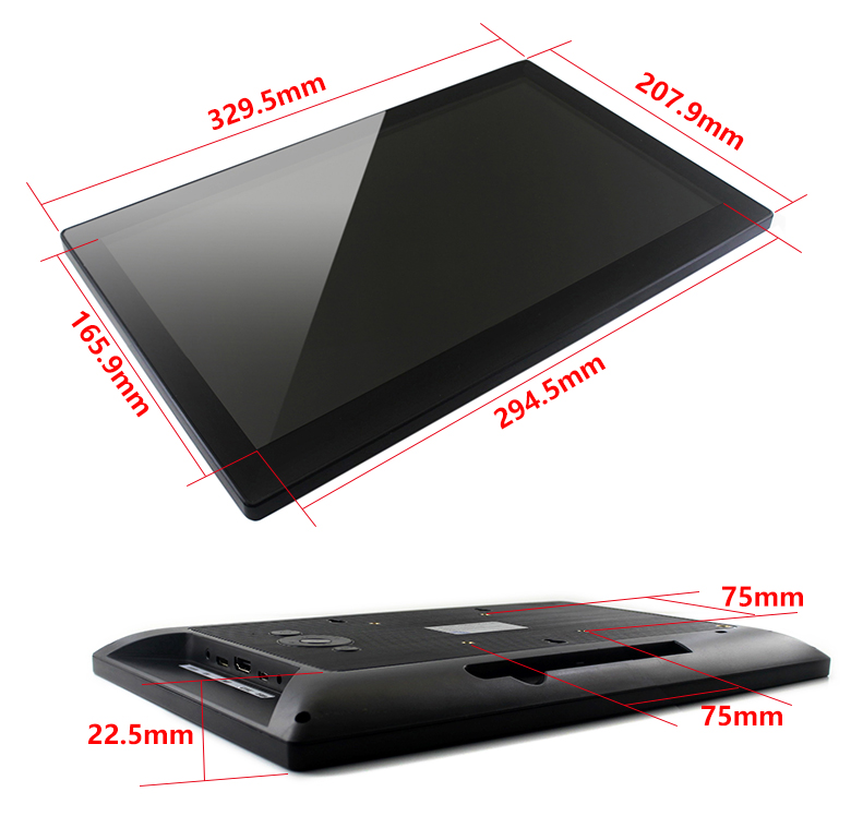
- 13.3inch IPS screen,1920x1080 high resolution
- Toughened glass capacitive touch panel, 6H hardness
- Supports popular mini PCs such as Raspberry Pi, BB Black, as well as general desktop computers
- When works with Raspberry Pi, supports Raspbian, Ubuntu, WIN10 IOT, single touch, and driver free
- When work as a computer monitor, supports Windows 10/8.1/8/7, ten-points touch, and driver free
- Multi languages OSD menu, for power management, brightness/contrast adjustment, etc.
- 3.5mm audio jack, supports HDMI audio output
- Embedded ferrite Hi-Fi speaker
- Also supports VGA input (specific cable is required and should be purchased separately)
- 75x75mm spacing mounting holes (M4 screw hole) for general wall mount
- Comes with 75° tilt angle stand
External Dimension
What's in the box?
1 x 13.3inch Capacitive Touch HDMI LCD
Resources
Wiki : www.waveshare.com/wiki/13.3inch_HDMI_LCD_(H)_(with_case)

Know how much rain you got overnight with this digital wireless rain station
Features
- Outdoor wireless sensor (range up to 100 meter)
- Detail display of rainfall data in 1hour, 24hour, week, month
and total since last reset(user selectable in inch or mm) - Indoor and outdoor temperature (°F to °C)
- Time and date with manual setting option
- 12 /24 hour time mode
- Calendar
- Time zone setting
- Time alarm
- Free standing
Specifications
- Rainfall display range: 0 to 19,999mm
- Outdoor temperature range: -40 ~ 65°C (-40°F to 149°F)
- Indoor temperature range: -9.9 ~ 60°C (-15.8°F to 176°F)
- Temperature accuracy: ±1.0°C5) Power requirements:
a) Receiver: 2 x "AA" alkaline batteries (not included)
b) Rain gauge: 2 x "AAA" alkaline batteries (not included) - Transmission range: up to 100meters( 330feet)
- Transmission frequency: 433MHz
What's in the box?
1 x Rain Gauge
1 x Receiver
1 x User Manual
2 x Screws

- Using the ITR20001 Reflective Photoelectric Sensor
- Five ITR20001/T infrared light detectors are used with higher sensitivity, wider detection range and anti-interference.
- Five-channel analog output, higher accuracy, so that the tracking range of the car is wide and stable
Connection Reference:
VCC: Connect 3.3~5V
GND: Connect GND
U1: Connect MCU.IO(Channel, analog output)
U2: Connect MCU.IO(Channel, analog output)
U3: Connect MCU.IO(Channel, analog output)
U4: Connect MCU.IO(Channel, analog output)
U5: Connect MCU.IO(Channel, analog output)
Specifications:
Note:
*Please allow 1-3mm difference due to manual measurement.
Package Includes:
1 x Infrared Tracking Sensor

Power-up your TV with Picade Console! It's a compact, Raspberry Pi-powered retro games machine with authentic arcade controls that plugs right into your TV, monitor, or other HDMI display.
Picade Console is fight stick-style arcade console that riffs off our new Picade with the same retro feel, same joystick and buttons, dedicated power button, and driven by the same powerful combo of the Raspberry Pi and Picade X HAT. It's beautifully packaged, comes with stickers and a neon-infused A3 Picade Console poster, and full assembly instructions.
It comes in kit form and takes an hour or two to build. The enclosure is made from powder-coated MDF and acrylic, giving it an authentic arcade look and feel. All you'll need to add is a Raspberry Pi, power supply, HDMI cable, and micro-SD card.
*TV not included! Using a CRT TV requires additional adaptors.
Video available on this unit at https://youtu.be/TiFBHOZROrw
Features
- Black, powder-coated panels
- Acrylic console with retro artwork
- Push-fit arcade buttons
- Joystick with black ball top
- Speaker (3W, 4Ω, 2.5" driver)
- Easy access with removable back panel
- Dedicated illuminated power button
- Grippy rubber feet
- Dimensions (assembled): 245x120x140mm
Picade X HAT features
- Easy DuPont connectors for buttons and joystick
- Push-fit speaker terminals
- I2S audio DAC with 3W amplifier (mono)
- Power management, power switch pins, and power button
- 4-way joystick inputs
- 6 player buttons
- 4 utility buttons
- Metal standoffs to hold your Picade X HAT securely
Extras
- Picade Console poster / assembly instructions
- Picade stickers
What's new!?
Picade Console is more compact and easier to build, but has a bunch of new features liked a dedicated power button, better cable routing out the back of the console with a panel-mount micro-USB connector for power, and slick new artwork.
The new buttons in Picade are lower profile, and the new joystick has a single connector rather than the eight spade connectors on our previous Picade joystick.
Picade X HAT is all-new and packed full of useful features. We've moved from more fiddly screw terminals to simple DuPont connectors that just push in, and the speaker terminals are the same easy push-fit connectors that we use on pHAT BEAT.
There's dedicated power management on-board Picade X HAT; just plug your micro-USB power supply into the HAT and it'll power your Pi through its pins. The power button connected to the HAT means that once your Pi is safely shutdown, the power will be cut completely to the Pi. A simple press of the power button will boot your Picade Console up again.
Software setup
We recommend the RetroPie operating system for your Picade. You can download it from the RetroPie website and then burn it to a micro-SD card with Etcher.
Connect a USB keyboard to your Pi, and connect to Wi-Fi in the RetroPie menu. Press F4 to exit to the terminal and then type curl https://get.pimoroni.com/picadehat | bash to run the Picade HAT installer.
Reboot your Pi, if it doesn't prompt you to. Press the "Alt" key on your keyboard and then select "Configure input" to configure your Picade Console's controls. You'll find that the sound and power button should both be working now too!
Where to find ROMs for RetroPie (free and legally) https://howchoo.com/g/otiwyjhlnzb/where-to-find-roms-for-retropie
and here http://cvaddict.com/article.php?articleid=15

You can also use these sensor boards with Home Assistant!
Features
- 7x AC Current Ports.
- 1x AC Voltage Ports.
- Provides Irms, Vrms, RealP, ApparentP, ReactiveP, PFactor, Frequency, EstimatedP.
- View/record data using Linux / Python / Emoncms / Grafana / MQTT and more.
- Configurable from serial port.
- Open Source Arduino Firmware.
- Stackable with RPICT8 Slave.
What's in the box?
1 x RPICT7V1 board
4 x Mounting Stand off with screws.
The listing does not include sensors and Raspberry pi.
Recommended Sensors
Voltage
Current
- SCT-013-000 (100A)
Technical Specifications
| Microcontroler | Atmel Atmega328p |
| MCU Frequency | 16Mhz |
| Operating Voltage | 5V |
| Waveform Sampling | 4400sps |
| Fastest Data Polling | 1400ms (all 7 channels) |
| Vertical Resolution | 12 bits (4096 steps) |
| Communication | UART Serial Port |
| Firmware | Arduino (open source) |
| Dimensions | 56x65mm |
| Programming port | 6 pin ISP |
| Compatible OS | Any supporting GPIO serial port access |
| Compatible Raspberrypi | All of Family 1,2,3,4 and Model A, B |
| Compatible CT | Current output type |
| AC Current Range | 30A |
| AC Voltage Range | 240V |
| Smallest Readable Current | Approx 50mA to 150mA |
Scope of Use
This development board/kit is intended for use for ENGINEERING DEVELOPMENT, DEMONSTRATION, OR EVALUATION PURPOSES ONLY and is not considered by LeChacal.com to be a finished end-product fit for general consumer use. Persons handling the product(s) must have electronics training and observe good engineering practice standards. As such, the goods being provided are not intended to be complete in terms of required design-, marketing-, and/or manufacturing-related protective considerations, including product safety and environmental measures typically found in end products that incorporate such semiconductor components or circuit boards. This
evaluation board/kit does not fall within the scope of the European Union directives regarding electromagnetic compatibility, restricted substances (RoHS), recycling (WEEE), FCC, CE or UL, and therefore may not meet the technical requirements of these directives or other related directives.

The HT16K33 is a memory mapping and multi-function LED controller driver. The max. Display segment numbers in the device is 128 patterns (16 segments and 8 commons) with a 13*3 (MAX.) matrix key scan circuit. The software configuration features of the HT16K33 makes it suitable for multiple LED applications including LED modules and display subsystems. The HT16K33 is compatible with most microcontrollers and communicates via a two-line bidirectional I2C-bus.
Features:
Operating voltage: 4.5V~5.5V.
Integrated RC oscillator.
I2C-bus interface.
16*8 bits RAM for display data storage.
Max. 16 x 8 patterns, 16 segments and 8 commons.
R/W address auto increment.
Max. 13 x 3 matrix key scanning.
16-step dimming circuit.
Selection of 20/24/28-pin SOP package types.
Applications:
Industrial control indicators.
Digital clocks, thermometers, counters, multi meters.
Combo sets.
VCR sets.
Instrumentation readouts.
Other consumer applications.
LED Displays.
Package included:
1 x Module
Getting Started
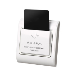
Although the reader does not read the information on the NFC card, it is triggered by a 125 khz NFC card

Single-core tinned copper wire is used, which is easy to weld and anti-oxidation, and is not easy to break. The copper wire can withstand a high temperature of 80°C, making it suitable for a variety of thermal overload applications. The single-strand copper core has strong resistance to tension and surge current, which is convenient for shaping. Packaged by reel, the copper core has a moderate diameter and clear lines, making it easy to use and store. Copper wire is suitable for welding notebooks, motherboards, LCD screens, displays and other circuit boards.
Features
- Material: Plastic and Metal
- Total length of about 250M
- Line: 30AWG
- Single sheath outer diameter of about: 0.55mm, copper core diameter of about 0.25mm.
- Temperature: 80 degrees, single-strand copper crossing tin, have antioxidant effects.
What's in the box?

Description:
Great for small 12 volt DC solar panel LED Lighting systems to conserve battery power; also well suited for occupancy LED lighting control and security LED Lighting systems
Specifications:
- Influence control: Light Infrared PIR
- Two light modes: all day/at night(Auto switching on when detecting people coming.)
- Super energy saving, super sensitivity within 7 meter distance.
- Built in light sensor which can identity day and night by itself,
- Sensor sensitivity distance: ≥7m
- Sensor sensitivity angle: 145°
- Load current:10A
- Working voltage:DC 5V-30V
- Delay time: If people leave, light will delay 30s-150s(Adjustable) to turn off
- Certificate: CE
- Suitable for use in homes, wardrobes, kitchens, stairs, camping tents...
- Size:50mm x 43mm x 20mm(approx)
- 5.5 x 2.1mm male to male cable length:1M(approx)
- 5.5 x 2.1mm male to female cable length:1M(aprpox)
- Color:Black
- 1 x PIR sensor
- 1 x 5.5 x 2.1mm male to male cable
- 1 x 5.5 x 2.1mm male to female cable

Specifications
- Type: Single Sided
- Base Material: Bakelite
- Thickness: approx. 1.5mm
- Hole Pitch: approx. 2.54mm
- Hole Diameter: approx. 1.0mm
- Size: approx. 65mm x 145mm
What's in the box?
5 x DIY Prototype PCB Board
Resources
Introduction to soldering
Video: How to solder properly
The secrets to good soldering

RASPBERRY PI BOARD NOT INCLUDED
Description:
Whether you're pulling-up or pulling-down, there's no need to frown! With the PUD board from ModMyPi, adding multiple pull-up or pull-down resistors to your Raspberry Pi project is easy!
If you want to detect an "output" with your Raspberry Pi, like a button being pressed or a motion sensor detecting movement, we can configure our Raspberry Pi's GPIO pin as an "input". That input pin can be in three states (known as Tri-State logic); "high", when 3.3V is applied, "low", when the pin is connected to 0V, and "floating" when the state is undefined. Floating voltages are troublesome in electronics as the input can either read high or low depending on various fluctuations in electrical noise. Like a gate flapping open and closed in the wind, someone needs to lock the gate closed, or wedge it open. If you leave it flapping, it's likely to hit someone on their bottom on the way through!
Like our gate, the best way to avoid a floating input is to "tie" your input pin either high or low to create a default state. This is usually achieved through the use of a pull-up or pull-down resistor, either connecting our input pin via a resistor to the Pi's 3.3V to achieve a 3.3V high state, or the GND line to achieve 0V low state.
Our PUD board takes the messy wiring out of adding a pull-up or pull-down resistor to your circuit. Simply wire up the sensor output to the single pin on the PUD board and add a shunt jumper to either pull up (u) or down (d)! Therefore when you apply a signal voltage from your sensor or switch, the Pi is easily able to sense into which logic state the pin has been pulled! No more trouble from floating I/O's!
The PUD boards connects across GPIO pins 11 to 18 (17 to 24 in BCM speak), and adds a jumper configurable pull-up or pull-down resistor to each GPIO pin: 11 (BCM 17), 12 (BCM 18), 13 (BCM 27), 15 (BCM 22), 16 (BCM 23) and 18 (BCM 24). Pin 17 (3.3V) & pin 14 (GND) are used to tie the pins!
The PUD Board Features:
- Add a pull-up or pull-down resistor to your GPIO with the swap of a jumper!
- Compatible with all Raspberry Pi Models Inc. A /B /2/3 & Zero/ZeroW
- Tiny board means it's easy to integrate into any circuit - takes up just 8 GPIO pins
- Connects across GPIO pins 11 to 18 inclusive (BCM 17 to 24)
- In-line 1kΩ current limiting resistors on each GPIO
- 10kΩ pull-up or pull-down resistors on each GPIO
- All 6 GPIO pins can be configured independently
- Includes 6 x 2 Pin Shunt Jumpers & 1 x PUD Board
- Jumper configurable pull-up or pull-down resistor on pins:
- 11 (BCM 17)
- 12 (BCM 18)
- 13 (BCM 27)
- 15 (BCM 22)
- 16 (BCM 23)
- 18 (BCM 24).
- Pin 17 (3.3V) & Pin 14 (GND) are used to tie the pins!
- To pull pin up, connect the jumper across "u" and the center pin
- To pull pin down, connect the jumper across "d" and the center pin
What's in the box:
1 x PUD Board
Tutorials:

This easy build bike light kit has just ten parts, making it a good introduction to electronics. The kit uses two ultra bright red LEDs, which flash rapidly, providing a highly visible light. Making it ideal for use as a rear bike light.
Alternatively it can be used as a night safety product or flashing eyes.
Features:
- Easy build kit making a great introduction to electronics.
- Great visibility for night time safety.
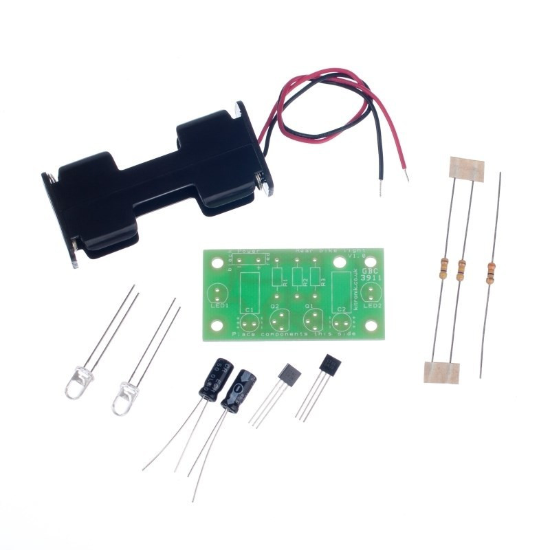
Contents:
- 1 x 2xAA Battery Cage with Leads.
- 2 x 470K Resistor.
- 1 x 33R Resistor.
- 2 x Capacitor, Electrolytic, 16V, 10uF.
- 2 x BC547 NPN Transistor.
- 2 x Red 5mm Water Clear LED - 30deg - 1000mCd.
Dimensions:
- Length: 48.5mm.
- Width: 25.5mm.
Requires:
- 2 x AA Batteries.
- Soldering Iron.
- Solder.
- Wire Cutters.
Resources:
- Click here to download the essential information

- Click here to download the full teaching resources
- Autodesk Files.
- 3D CAD Files.
This easy build bike light kit has just ten parts, making it a good introduction to electronics. The kit uses two ultra bright red LEDs, which flash rapidly, providing a highly visible light. Making it ideal for use as a rear bike light.
Alternatively it can be used as a night safety product or flashing eyes.
Caution:
- This is an educational kit and should be used in conjunction with a commercially available bike light.

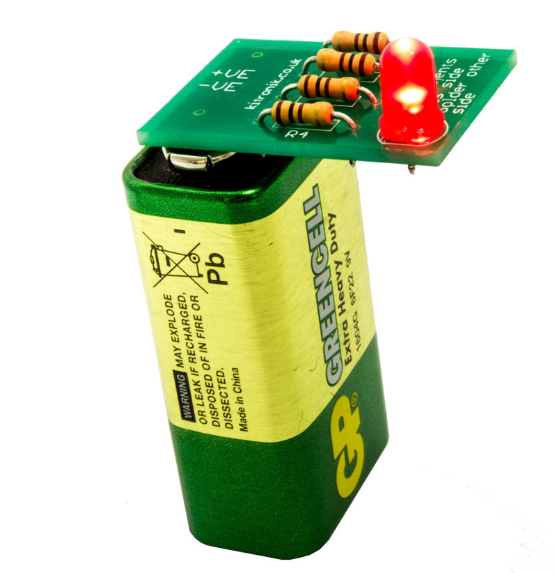
Our learn to solder pack is the ideal low cost solution for teaching soldering in the classroom/after school club. The pack provides all of the parts and PCB's required for a class size of 25 and also includes a 9V battery for testing purposes. Each pack comprises; 25 x PCBs, 100 x 100 ohm resistors, 25 x LED's, and a 9V PP3 battery.
We have also produced a step by step guide to soldering, which covers; equipment, solder, tinning & cleaning, soldering in 8 steps, de-soldering in five steps, wire preparation, examples of good and bad solder joints, basic PCB repair, resistor information, LED information, full step by step build information for the kit, and how the learn to solder kit works. This guide covers everything that you might need to discuss with students and can form the basis of your lesson plan.
Using the kits and the step by step guide, each student will solder four resistors and one LED to their PCB before pressing it to the terminals of the 9V battery to check that their board works. Using the guides they will be able to examine their own work and troubleshoot problems. The battery pads on the PCBs have been shaped inline with the battery terminals on a PP3 battery making it straightforward to see which way around it should be placed on the battery.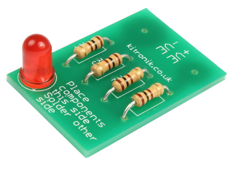
Features
- Purpose built PCBs that can be tested, once built, with the supplied 9V PP3 battery.
- Low cost classroom pack for 25 students.
- Easy build kit.
- Full teaching resources and step by step guides available for this kit below.
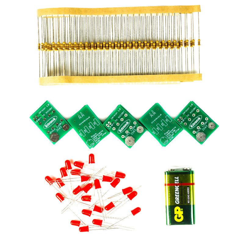
What's in the box?
100 x 100 ohm Resistors.
25 x Red 5mm Diffused LED - 275mCd.
25 x Learn To Solder PCBs.
1 x 9V Zinc Chloride PP3 Battery.
Dimensions
- Built Height: 11mm.
- PCB Length: 31mm.
- PCB Width: 21mm.
- PCB Height: 1.5mm.