
Generic2


USB-C to header/solder breakout board. Handy for your USB-C powered projects.
What's in the box?
1 x USB-C breakout pcb
You might need want to solder a header on this board for use with jumpers cables.
RP2040 MCU Board Zero, a Pico-like MCU board based on Raspberry Pi RP2040, Castellated module, suitable for SMD applications.
Board specifications
- RP2040 microcontroller chip designed by Raspberry Pi in the United Kingdom
- Dual-core Arm Cortex M0+ processor, flexible clock running up to 133 MHz
- 264KB of SRAM, and 2MB of on-board Flash memory
- USB-C connector, keeps it up to date, easier to use
- Castellated module allows soldering direct to carrier boards
- USB 1.1 with device and host support
- Low-power sleep and dormant modes
- Drag-and-drop programming using mass storage over USB
- 29 × multi-function GPIO pins (20× via edge pinout, others via solder points)
- 2 × SPI, 2 × I2C, 2 × UART, 4 × 12-bit ADC, 16 × controllable PWM channels
- Accurate clock and timer on-chip
- Temperature sensor
- Accelerated floating-point libraries on-chip
- 8 × Programmable I/O (PIO) state machines for custom peripheral support
C/C++,MicroPython support
Comprehensive SDK, dev resources, tutorials to help you easily get started
29 × multi-function GPIO pins
configurable pin function, allows flexible development and integration
What's in the box?
1 x RP2040-Zero
3 x headers (unsoldered)
Resources
You'll find loads of usable info at the very similar Waveshare board
RP2040 MCU Board Zero, a Pico-like MCU board based on Raspberry Pi RP2040, Castellated module, suitable for SMD applications.
Board specifications
- RP2040 microcontroller chip designed by Raspberry Pi in the United Kingdom
- Dual-core Arm Cortex M0+ processor, flexible clock running up to 133 MHz
- 264KB of SRAM, and 2MB of on-board Flash memory
- USB-C connector, keeps it up to date, easier to use
- Castellated module allows soldering direct to carrier boards
- USB 1.1 with device and host support
- Low-power sleep and dormant modes
- Drag-and-drop programming using mass storage over USB
- 29 × multi-function GPIO pins (20× via edge pinout, others via solder points)
- 2 × SPI, 2 × I2C, 2 × UART, 4 × 12-bit ADC, 16 × controllable PWM channels
- Accurate clock and timer on-chip
- Temperature sensor
- Accelerated floating-point libraries on-chip
- 8 × Programmable I/O (PIO) state machines for custom peripheral support
C/C++,MicroPython support
Comprehensive SDK, dev resources, tutorials to help you easily get started
29 × multi-function GPIO pins
configurable pin function, allows flexible development and integration
What's in the box?
1 x RP2040-Zero with pre-soldered headers
Resources
You'll find loads of usable info at the very similar Waveshare board

400 Point solderless breadboard. Perfect for solderless electronic projects.
Specifications
- 400 tie points total: 300 tie-point IC-circuit area plus two 50 tie-point distribution strips providing 4 power rails.
- White ABS plastic body with black printed legend.
- Color legend on distribution strips.
- Size: 84mm x 54.3mm x 8.5mm
- Peelable adhesive tape backing provided for attaching to a surface.
What's in the box?
1 x 400 Point Breadboard
Resources
High-Precision DS3231 I2C Real-Time Clock (RTC) Module
Keep flawless time on your microcontrollers even when disconnected from mains power. The DS3231 is an ultra-accurate I2C Real-Time Clock that features an integrated temperature-compensated crystal oscillator (TCXO). By housing the crystal inside the chip itself and tuning it against temperature changes, this module guarantees long-term timekeeping precision while lowering your project's overall component count.
Key Capabilities
Complete Time & Calendar Tracking: Tracks seconds, minutes, hours, day, date, month, and year with full leap-year compensation valid up to the year 2100. It supports both 24-hour and 12-hour (with AM/PM indicators) formats.
Dual Alarms & Outputs: Features two programmable calendar alarms alongside a configurable square-wave output signal.
Power-Failure Resilience: An onboard voltage reference and comparator circuit constantly monitor your main VCC line. If it drops, the board automatically shifts to its battery backup, triggering a reset output if needed. The
/RSTpin can also be toggled manually for microprocessor resets.Integrated Digital Thermometer: Includes an onboard digital temperature sensor accessible over the same I2C bus, featuring an accuracy profile of ±3°C.
Extended Backup Performance: Timekeeping and temperature readings remain uninterrupted during a primary power failure. Once main power returns, the module assists in smoothly restarting your host microcontroller.
Technical Specifications
Dimensions: 38mm x 22mm x 14mm
Weight: 8g
Operating Voltage: 3.3V to 5.5V
Core Controller: High-accuracy DS3231 RTC IC
Timing Accuracy: ±2ppm across a 0°C to 40°C threshold (translates to roughly a 1-minute variance per year)
Onboard Memory: AT24C32 EEPROM chip providing 32K of extra storage space
Bus Communication: I2C interface running at speeds up to 400kHz (optimized at 5V)
Expandable Address Routing: Devices can easily be daisy-chained on the same line. The default EEPROM address is
0x57, but it can be changed manually using the A0, A1, and A2 solder jumpers.Backup Power: Utilizes a standard CR2032 coin cell battery to preserve internal registers during a system shutdown.
What's in the box?
1 x RTC Module
1 x Battery
Resources

- Ribbon of 40 x 300mm
- Male to Female
Features
- Tested for Compatibility with the Raspberry Pi
- Breadboard compatible
- Colour: Multi-coloured
What's in the box?
40 x 200mm Male to Female Jumper cables

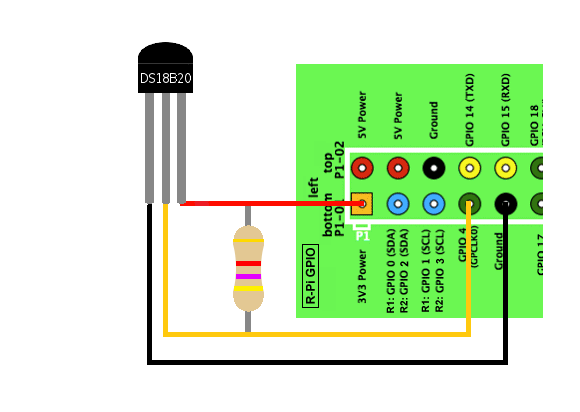
The only downside is they use the Dallas 1-Wire protocol, which is somewhat complex, and requires a bunch of code to parse out the communication. If you want something really simple, and you have an analog input pin, the TMP36 is trivial to get going.
We toss in a 4.7k resistor, which is required as a pullup from the DATA to VCC line when using the sensor.
Cable specs
- Stainless steel tube 6mm diameter by 30mm long
- Cable is 36" long / 91cm, 4mm diameter
- Contains DS18B20 temperature sensor
- If your sensor has four wires - Red connects to 3-5V, Black connects to ground and White is data. The copper wire is soldered to the wire shielding
- If your sensor has three wires - Red connects to 3-5V, Blue/Black connects to ground and Yellow/White is data
DS18B20 Technical specs
- Usable temperature range: -55 to 125°C (-67°F to 257°F)
- 9 to 12 bit selectable resolution
- Uses 1-Wire interface- requires only one digital pin for communication
- Unique 64 bit ID burned into chip
- Multiple sensors can share one pin
- ±0.5°C Accuracy from -10°C to 85°C
- Temperature-limit alarm system
- Query time is less than 750ms
- Usable with 3.0V to 5.5V power/data
What's in the box?
1 x DS18B20 Digital temperature sensor
1 x 4.7k resistor
Resources
Adafruit's Raspberry Pi Lesson: DS18B20 Temperature Sensing

Specifications
- Each Relay has LED indication when ON
- SPDT Relays with terminal block outputs.
- Relay Coil voltage: 5 VDC
- Power Requirement: 5 VDC
- 10A 250V AC / 10A 30V DC
What's in the box?
1 x Two channel 5V DC Relay Module
Resources
Interfacing with a relay : https://tutorials-raspberrypi.com/raspberry-pi-control-relay-switch-via-gpio/

Specifications
- Multicolored
- 300mm
- Female to Female
What's in the box?
1 x Ribbon of 40 lines
Resources
This is a HDMI to VGA converter which will allow you to convert your digital HDMI output signal, into an analog signal. Perfect for hooking your Pi up to a VGA computer screen.
Specifications
- HDMI(Type A) to VGA(D-SUB)
- Colour: Black
What's in the box?
1 x HDMI to VGA Converter
You will find this motor and wheel can be installed conveniently with many fixed locations on the acrylicplate of most robot chassis, and is very suitable for Raspberry Pi, Arduino and MCU robotics.
Features
- Working Voltage: 3-6V
- Specifications: double shaft, the wheel can be attached at both sides of the motor
- Gear ratio: 1:48
- No-load speed (at 5V): 90RPM
- No-load current (at 5V): 190mA
- Rated Torque: 78mN.m (0.8kgf.cm)
- Wheel Diameter: Black Wheel: 66mm
- Wheel Thickness: Black Wheel: 25mm
- Wire length (optional): 15cm
- Motor Size: 70 x 36.5 x 24.5mm (L*W*H)
- Net Weight: 65g
What's in the box?
1 x motor
1 x wheel
You might also need a mounting bracket for this wheel

This economical sensor provides 2cm to 400cm of non-contact measurement functionality with a ranging accuracy that can reach up to 3mm. Each HC-SR04 module includes an ultrasonic transmitter, a receiver and a control circuit.
There are only four pins that you need to worry about on the HC-SR04: VCC (Power), Trig (Trigger), Echo (Receive), and GND (Ground). You will find this sensor very easy to set up and use for your next range-finding project!
Specifications
- Model: HC-SR04
- Color: Blue Silver
- Working voltage : 5V(DC)
- Static current: Less than 2mA.
- Output signal: Electric frequency signal, high level 5V, low level 0V.
- Sensor angle: Not more than 15 degrees.
- Detection distance: 2cm~450cm.
- High precision: Up to 3mm
- Mode of connection: VCC / trig(T) / echo(R) / GND
- Module Working Principle:
- Adopt IO trigger through supplying at least 10us sequence of high level signal
- The module automatically send eight 40khz square wave and automatically detect whether it receive the returning pulse signal
What's in the box?
1 x HC-SR04 distance sensor
You might need a bracket to mount this sensor
Resources
Follow this tutorial at ThePiHut.
https://thepihut.com/blogs/raspberry-pi-tutorials/hc-sr04-ultrasonic-range-sensor-on-the-raspberry-pi
Using GPIOZero

Specifications
- Product: SG90 Servo
- Torque: 2.0kg/cm(4.8V), 2.2kg/cm(6V)
- Speed: 0.09s/60°(4.8V), 0.08s/60°(6V)
- Rotate angle: 180°
- Operating voltage: 4.8 ~ 6V
- Gear: plastic
- Dead band: 7us
- Weight: 10.5g
- Dimension: 22.8mm × 12.2mm × 28.5mm
What's in the box?
1 x servo motor
Resources
ExplainingComputers has a great video on using this servo https://www.youtube.com/watch?v=xHDT4CwjUQE&t=389s

Note: This kit comes unassembled. So you will need to assemble it yourself, referring to the Assembly Guide.
This is a Pan Tilt Servo Kit for Camera (Unassembled). It is basically a versatile 2-degree of freedom Servo Holder, perfect for securing your Raspberry Pi Camera, small gripper, or any other compact device essential for your project.
The kit comprises 2 units of high-quality 180 Degree SG90 Servo Motors, allowing for easy assembly and immediate use. Think of it as a mini robotic arm that is ideal for educational purposes and practical learning experiences.
Unleash your creativity by incorporating this servo holder kit into Artificial Intelligence (AI) projects. Seamlessly integrate a camera for applications like auto-targeting or object-following functionalities.
Features
- 2-Degree of Freedom Pan Tilt Servo Kit
- 2 x 180 Degree Servo Motor included
- Simple and Compact robotic arm
- Compatible with Raspberry Pi Camera
- Materials: ABS Plastics
What's in the box?
1 x Pan Tilt Servo Kit
2 x 180 Degree SG90 Servo Motors
1 x Small Phillip Screwdriver
Resources
These high-power LEDs deliver smooth, uniform illumination without glare or visual striping, making them an excellent light source for video camera lighting, custom LED lamps, aquariums, and DIY illumination projects.
⚠️ Important Thermal Warning: These high-output LEDs generate substantial heat during operation. To prevent thermal runaway and permanent damage, they must be mounted to an adequate heatsink.
Technical Specifications
Optical & Physical Properties
- Luminous Intensity (Max): 260 Lumens
- Colour Temperature: 10,000K – 15,000K (Cool White / Daylight spectrum)
- Viewing Angle: 120°
- Dimensions: 14.5mm x 7.5mm
- Net Weight: 2 g
Electrical & Power Profiles
- Total Power Consumption: 1 Watts
- Power Dissipation: 1W
- Continuous Forward Current: 280 mA
- Peak Forward Current: 350 mA
- Forward Voltage: 2.5V (Typical) | 4V (Maximum)
- Reverse Voltage: 5V
- Reverse Current: 10 µA
Thermal Thresholds
- Thermal Resistance: 12 °C/W
- Maximum LED Junction Temperature: 120°C
- Operating Temperature Range: -35°C to +90°C
- Storage Temperature Range: -40°C to +100°C
What's in the box?
10 x Cool White metal base LED
Resources

NOTE: These sensors are not capacitive sensors and rely on physical interaction with soil and moisture which prevents them from being used for long-term monitoring. This sensor is only suitable as for use with learning!
This is a summary of the soil moisture sensor that can be used to detect moisture, when the soil is dry, the module outputs a high level. Use this sensor to build an automatic watering system.
Specifications
- Operating voltage: 3.3V~5V.
- Adjustable sensitivity (blue digital potentiometer adjustment)
- Dual output mode, analog output more accurate.
- A fixed bolt hole for easy installation.
- Power indicator (red) and digital switching output indicator (green).
- LM393 comparator chip, stable.
- PCB Dimension: 3cm x 1.5cm.
- Soil Probe Dimension: 6cm x 2cm.
- Cable Length: 21cm.
Connections
VCC: 3.3V-5V.
GND: GND.
DO: digital output interface (0 and 1).
AO: analog output interface.
What's in the box?
1 x Soil moisture detector module
1 x Probe
5 x Jumper Cables
Resources
Setup with Raspberry Pi

- 2 X 20 pins
- Pitch: 2.54mm
- 12.2mm solder tails (pin's length)
- Gold plated
What's in the box?
1 x 2x20 female header
Resources
Technical Drawing

DHT11 is the most common sensor that is usually used by students and makers out there. The main function of this sensor is to measure the temperature and humidity of the surroundings. The sensor is also factory calibrated and hence easy to interface with any microcontrollers like Arduino. The sensor can measure temperature from 0°C to 50°C and humidity from 20% to 90% with an accuracy of ±1°C and ±1%. So if you are looking to measure in this range then this sensor might be the right choice for you!
The DHT11 sensor can either be purchased as a sensor or as a module. Either way, the performance of the sensor is the same. The sensor will come as a 4-pin package out of which only three pins will be used whereas the module will come with three pins as shown below. The only difference between the sensor and module is that the module will have a filtering capacitor and pull-up resistor inbuilt so that you can just simply connect wires and start your project!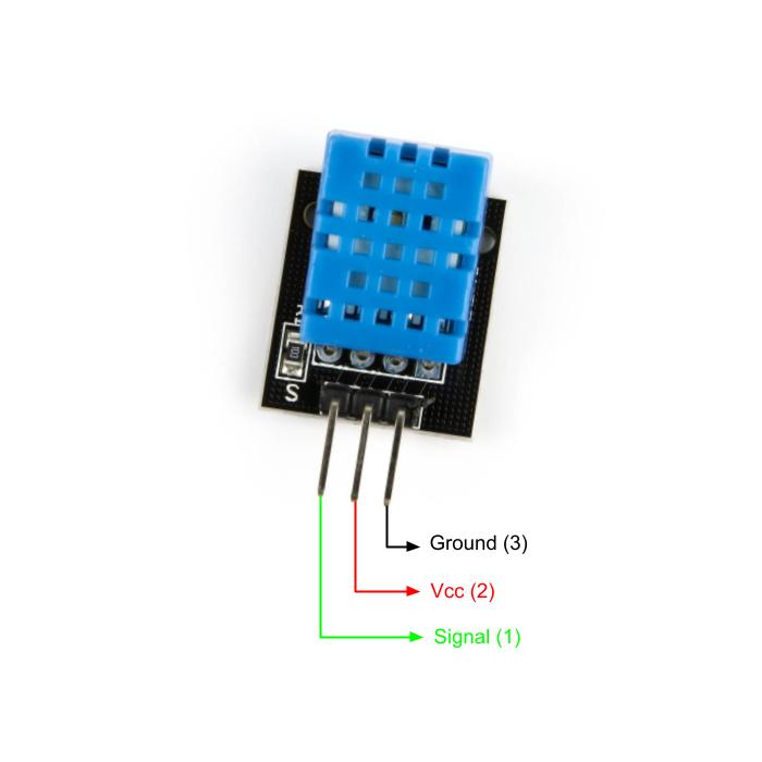
Pinout Configuration
- Vcc: Power supply 3.5V to 5.5V
- Signal: Outputs both Temperature and Humidity through serial Data
- Ground: Connected to the ground of the circuit
Features
- With calibrated digital signal output
- Adopt special digital module acquisition technology and temperature and humidity sensing technology to ensure high reliability and excellent long-term stability.
- The sensor is composed of a resistance liquid contact element and an NTC temperature measuring element and is connected to a high-performance 8-bit microcontroller. Therefore, the product has the advantages of high quality, ultra-fast response, strong anti-interference ability, and high-cost performance.
- The single-wire serial interface makes system integration simple and fast. Ultra-small size, low power consumption, and a signal transmission distance of more than 20 meters make it the best choice for any application, even the most demanding ones. The product is easy to connect and can be plugged directly into the sensor expansion board.
Application
- Measure temperature and humidity
- Widely used for IoT projects
- Local Weather station
- Automatic climate control
- Environment monitoring
Specifications
- Operating Voltage: 3.0V to 5.5V
- Operating current: 0.3mA (measuring) 60uA (standby)
- Output: Serial data
- Temperature Range: 0°C to 50°C
- Humidity Range: 20% to 90%
- Resolution: Temperature and Humidity both are 16-bit
- Accuracy: ±1°C and ±1%
What's in the box?
1 x DHT11 Temperature and Relative Humidity Sensor Module
Resources
- How to setup a DHT11 with your Raspberry Pi.
- DHT 11 Datasheet
- https://github.com/adafruit/DHT-sensor-library

Tactile Switches or tact switches are an on/off electronic switch that is only on when there is some pressure put on it or when the button is pressed. As soon as the tactile switch button is released and the pressure has been took off, the circuit is then broken.
- Size: (Approx.)6x6x5mm
- Life: 100000 times
- Quantity: 5pcs
- Current: 50mA
- Voltage: 12V
What's in the box?
5 x Tactile Switches
Resources
Python library
Introduction to Buttons and Switches
Types of buttons and switches

The 28BYJ-48 motor runs in full step mode, each step corresponds to a rotation of 11.25°. That means there are 32 steps per revolution (360°/11.25° = 32). In addition, the motor has a 1/64 reduction gear set.
The power consumption of the motor is around 240mA.
The ULN2003 is one of the most common motor driver ICs, consisting of an array of 7 Darlington transistor pairs, each pair is capable of driving loads of up to 500mA and 50V. Four out of seven pairs are used on this board.
The board has four LEDs that show activity on the four control input lines (to indicate stepping state). They provide a nice visual when stepping.
The board also comes with an ON/OFF jumper to isolate power to the stepper Motor.
Specifications
- High quality stepper motor with ULN2003 driver
- Suitable for microcontroller development
- Voltage: DC 5V
- Diameter: 28mm
- Step Angle: 5.625 x 1/64
- Reduction Ratio: 1/64
- Dimensions: 1.38 in x 1.18 in x 0.39 in (3.5 cm x 3.0 cm x 1.0 cm)
- Weight: 1.45 oz (41 g)
What's in the box?
1 x stepper motor
1 x ULN2003 driver
Resources
How to control a ULN2003 stepper motor with Raspberry Pi