
Generic2


Features
- Versatile Voltage Range: This photosensitive sensor module operates effectively within a supply voltage range of DC 3.3-5V, making it suitable for various applications and systems requiring different power levels.
- Sensitive Light Detection: Utilizing a highly sensitive photoresistor sensor, the module can accurately detect ambient light intensity, triggering microcontrollers or relay modules to respond appropriately to changing light conditions.
- Adjustable Brightness Sensitivity: Featuring an adjustable potentiometer, users can easily fine-tune the sensitivity of light detection, allowing for customized performance based on specific environmental requirements.
- Clear Signal Output: The module provides a clean digital output signal with strong driving capability exceeding 15mA,reliable communication with microcontrollers for precise monitoring of light levels.
- Easy Installation: The module features screw mounting holes for easy installation and includes a power indicator for quick status checking, enhancing usability in a variety of settings.
Specifications
- Part Name: Light Sensor Module
- Material: PCB
- Size: 32 x 14 mm
- Colour: Blue
What's in the box?
1 x Photosensitive Sensor Module
NFC NTAG213 tag stickers are small adhesive tags that use Near Field Communication (NFC) technology to wirelessly transfer data when placed close to a compatible device, like a smartphone. The NTAG213 chip is specifically designed for simple and versatile NFC applications, featuring a memory size of 144 bytes and operating at a frequency of 13.56 MHz. These stickers are popular for a wide range of applications, including:
1. Smart Home Automation: Can be placed on objects or around the house to trigger actions on NFC-enabled smartphones, such as turning on lights or setting up scenes.
2. Contactless Sharing: Used for storing small amounts of information like URLs, contact information, or Wi-Fi credentials, making it easy to share with others by tapping a smartphone.
3. Inventory and Asset Management: Can be used in retail, warehouses, or offices for tracking items, verifying authenticity, or updating inventory records quickly with a mobile device.
4. Marketing and Event Management: Often used in events, businesses, or museums where visitors can tap their phones on the sticker to get more information about an exhibit, product, or promotion.
5. Access Control: Can be programmed to unlock doors or perform secure actions when authenticated with compatible devices.
These tags are typically very affordable, making them a popular choice for many personal and business-related NFC applications.
What's in the box?
10 x 13.56MHz RFID stickers
The Ferrule Kit can tidy up your wire ends and make it easy to use with other electrical headers and terminals, especially in industrial applications. The kit comes with a total of 1200 pieces for 8 different wire sizes so that you have plenty of options to tidy up your wire ends.
You will find the rest of our lugs selection here
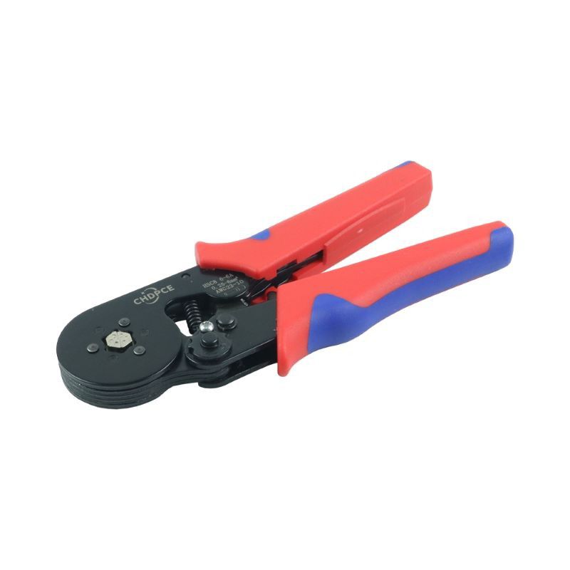
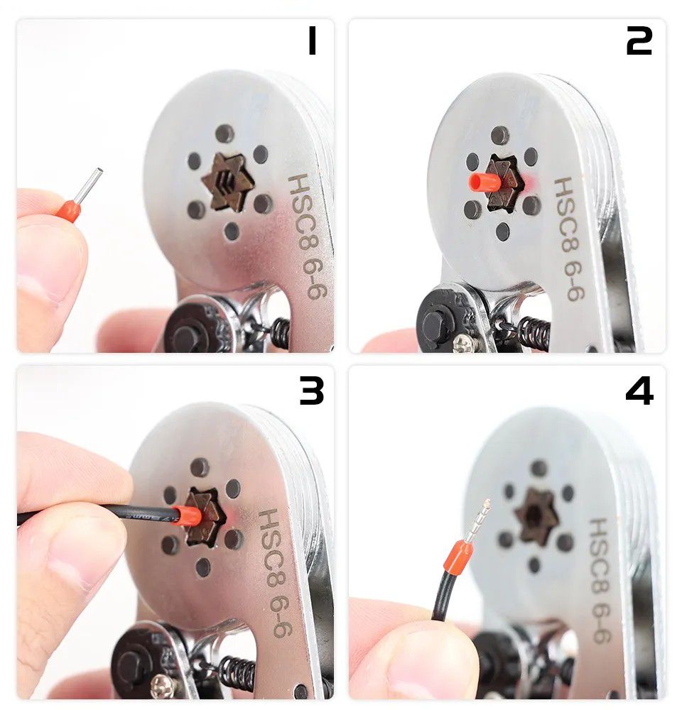
To use the Ferrule Kit, you need to use a Crimping Plier. So you can use the below HSC6-6 Crimping Plier with your Ferrule Kit. This crimping plier comes with a hexagonal crimper and adjustable pressure regulator. It is also designed to have a soft ergonomic handle for a comfortable grip.
What's in the box?
1200 x terminals (lugs)
Resources
This continuous rotation servo converts standard RC servo position pulses into continuous rotation speed. The default rest point is 1.5 ms, but this can be adjusted by using a small screwdriver to turn the middle-point adjustment potentiometer. Pulse widths above the rest point result in counterclockwise rotation, with speed increasing as the pulse width increases; pulse widths below the rest point result in clockwise rotation, with speed increasing as the pulse width decreases.
Specifications
- Product model: SG90
- Colour: Blue
- Dimensions: 22.8 x 22.4 x 12mm
- Rotation Angle: 360°( Continuous rotation)
- Operating Speed: 0.1 second/ 60 degree(4.8V).
- Gear Medium: NylonOperating
- Mode: AnalogControl
- Signal: PWMStall
- Torque: 1.5kg/cmTemperature
- Range: 0 ℃- 55 ℃
- Dead Band Width: 10usec.
- Operating Voltage: 4.8VPlug
- Connector Wire Length: 250mm(Brown: Negative; Red: Positive; Orange: Pulse Input)
- Accessories: Multi-arm, Fixing screws
- Application: Mini Car / Mini Ship / Helicopter & Airplane
- Steering Gear Control: The control of the steering gear generally requires a time base pulse of about 20ms, and the high level part of the pulse is generally the angle control pulse part in the range of 0.5ms~2.5ms.
Servo 360 Degree - The steering gear is actually equivalent to a geared motor with infinitely variable speed, which can control the speed and direction of the rotation. There is no 0-360 degree angle control function.
What's in the box?
1 x Micro 360 Degree Continuous Rotation Servo
This Multifunctional Smart Meter is a compact, all-in-one solution designed for real-time tracking of power metrics. Whether you're managing an control panel, a DIY solar setup, or monitoring home appliance efficiency, this meter provides the data you need at a glance.
Comprehensive Data Monitoring
Track six essential electrical parameters simultaneously on a single, high-clarity display:
Voltage (V)
Current (A)
Active Power (W)
Frequency (Hz)
Power Factor (PF)
Total Energy Consumption (kWh)
4. This is an entry level measuring solution. Do not expect 100% accuracy.
What's in the box?
1 x Multifunctional Smart Meter

Rocker Switches house a button for operation that can be pressed on either end like a seesaw to connect or disconnect an electrical circuit. They are often used as ON/OFF switches on the main power supplies for electronic devices.
Specifications
- 250 V
- 3A
- 21mm x 15mm at the top
What's in the box?
1 x Rocker Switch
Resources
Python library
Introduction to Buttons and Switches
Types of buttons and switches
Please note: Servo is not included with this product
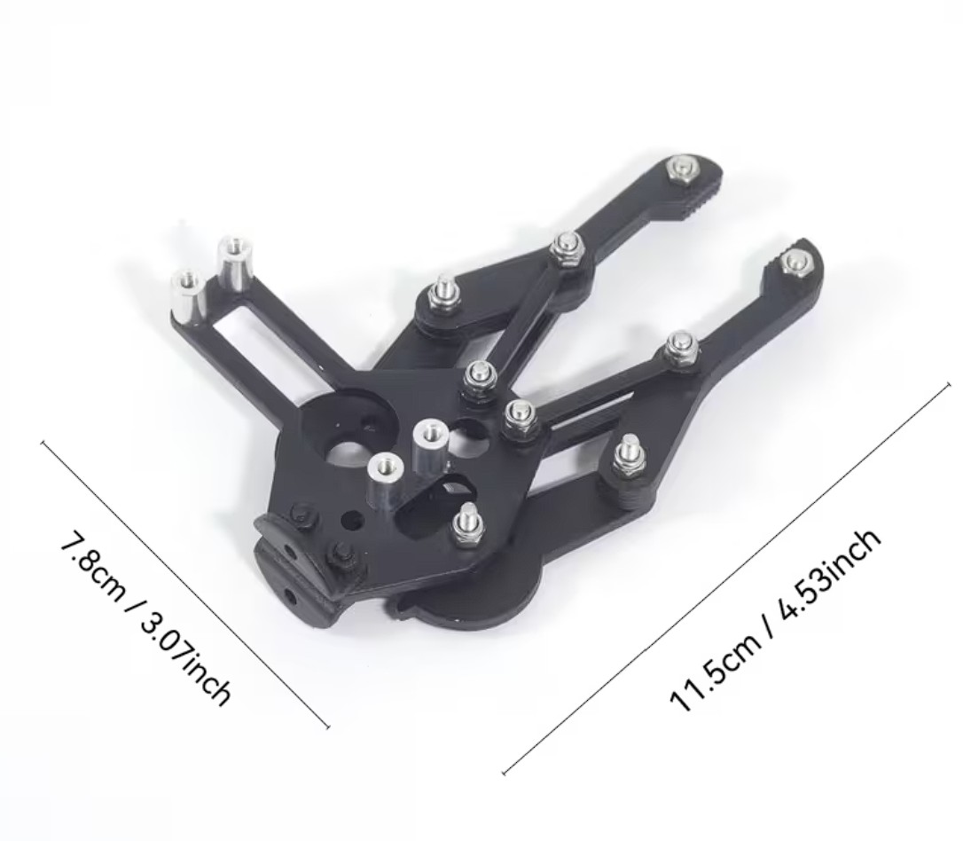
Elevate your robotics and mechanical projects with our High-Strength Metal Servo Arm, engineered specifically for high-torque applications. Whether you are building an industrial prototype or an advanced classroom project, this component provides the rigid connection necessary for precision movement.
Key Features
- Perfect Compatibility: Designed specifically for use with MG995 Servo Motors (and other standard 25T spline servos), ensuring a snug, slip-free fit.
- Maximum Durability: Made of high-strength metal components, this arm won't flex or stripped under pressure like standard plastic alternatives.
- Project Ready: Ideally suitable for educational science kits, DIY robotics, and STEM curriculum where reliability and longevity are essential.
What's in the box?
1 x Servo controlled Robotic Mechanical Claw
Resources

This battery box is designed for use as a nice switchable, portable power pack, and fits any four alkaline or rechargeable AAA batteries in series. The body is moulded in black ABS Resin and has a slide on detachable lid which can be locked for extra security through use of a small provided screw. It even includes a very useful miniature on-off slide switch which is very handy for wiring to projects that don't have a switch! Connection is via two flexible stranded red (positive) & black (negative) 26AWG wire leads, which are approximately 150mm in length.
- Battery Cell Size AAA
- Number of Cells 4
- Body Material ABS Resin
- Height 19.0 mm, Length 69.0 mm, Width 64.5 mm
- Terminal Type Wire Lead
- Type Battery Box
- Weight 0.03300 kg
What's in the box?
1 x switched battery box
Need batteries? You will find our battery selection here
- Power supply: 5V
- Switching type: Bistable(Latch)
- Onboard button: test trigger load on or off
- Triggering sensor modules can also be used to trigger the load on/off, as long as the trigger is low voltage.
- Relay control load maximum: 250V 10A (AC) and 30V 10A (DC)
- LED Indicator lights
- Size: 6cm x 3.5cm
What's in the box?
1 x bistable relay module
1 x trigger wire
These clips are great for protecting your fingers whilst assembling sewing projects. Why limit yourself to fabric though, we could also see them coming in useful for papercraft projects, taming uncooperative cables or combining with some string to make a snazzy photo display.
They come in a handy storage tub with 100 clips in a mix of 8 colours (pink, red, orange, yellow, green, blue, purple and clear). The flat side of the clips has guide markings 5, 7 and 10mm in from the edge, which helps keep your seams precisely lined up.
Specifications
- Width: 10mm
- Length: 27mm
- Clip thickness (fully open): approx. 90mm
What's in the box?
1 x tub of 100 clips
Add touch control to your electronics projects in seconds! The BMT Capacitive Touch Module is a "plug-and-play" sensor that works just like a smartphone screen. With just three pins (VCC, GND, and Signal), it is incredibly easy to wire to any microcontroller. It replaces old-fashioned clicky buttons with a modern touch surface that never wears out. Perfect for school projects, smart mirrors, and custom LED controllers!
Features
- Touch sensor module sensor
- When touching, S outputs a high; touch again, S will output low
- Power Range: 3-5V
- Current: 5MA
- Interface: G (GND), V (vcc), S (signal)
What's in the box?
1 x TTP223B Touch Sensor Module
The 4-pin TCRT5000 module is significantly more versatile than the 3-pin version because it provides both a Digital Output (D0) and an Analog Output (A0).
The Digital pin is perfect for "Yes/No" detection (like staying on a line), while the Analog pin allows you to see the intensity of the reflection, which is useful for measuring varying shades of gray or very small changes in distance.
Features
- Compatibility: Perfectly designed for Arduino projects, ensuring seamless integration and operation.
- Advanced Sensing: Utilizes IR technology with TCRT5000 sensors for accurate detection of reflective materials or barriers.
- Easy to Use: Simplified setup, suitable for beginners and professionals alike.
- Versatility: Ideal for a wide range of applications including line tracking robots, object detection, and automatic control systems.
- Optimized Design: Compact form factor for efficient performance.
Specifications
- Colour: Blue
- Material: ABS
Due to different batches, there may be differences in product printed text, which will not affect use.
What's in the box?
1 x Infrared Reflective Sensor
The 4-pin TCRT5000 module is significantly more versatile than the 3-pin version because it provides both a Digital Output (D0) and an Analog Output (A0).
The Digital pin is perfect for "Yes/No" detection (like staying on a line), while the Analog pin allows you to see the intensity of the reflection, which is useful for measuring varying shades of gray or very small changes in distance.
1. Hardware Connections (4-Pin Module)
| Module Pin | Raspberry Pi Pin | Physical Pin # | Function |
| VCC | 3.3V Power | Pin 1 | Power for the IR LED and comparator. |
| GND | Ground | Pin 6 | Common ground. |
| D0 | GPIO 17 | Pin 11 | Goes LOW when a reflection is detected. |
| A0 | See Note Below | — | Provides a voltage (0V to 3.3V) based on reflection. |
Important: The Raspberry Pi does not have a built-in Analog-to-Digital Converter (ADC). You cannot plug the A0 pin directly into a Pi GPIO and read its value. You have two choices:
- Ignore A0: Use only D0 for simple line following.
- Use an ADC Chip: Connect A0 to an MCP3008 chip if you need precise reflection data.
Python Code (gpiozero):
from gpiozero import DigitalInputDevice
from signal import pause
# TCRT5000 D0 is connected to GPIO 17
# pull_up=True because the sensor output is Active Low
sensor = DigitalInputDevice(17, pull_up=True)

def detected():
   print("Reflection Detected! (LED on module should be lit)")

def cleared():
   print("Reflection Lost.")

sensor.when_activated = detected
sensor.when_deactivated = cleared

print("Starting TCRT5000 Digital Test...")
pause()Wiring A0 through an ADC:
Connect A0 from the sensor to CH0 on the MCP3008.
Connect the MCP3008 to the Pi via the SPI pins (GPIO 8, 9, 10, 11).
Python Code (gpiozero with MCP3008):
from gpiozero import MCP3008
import time

# Create a reference to the Analog sensor on Channel 0 of the ADC
reflectivity = MCP3008(channel=0)

while True:
   # Value will be between 0.0 (no reflection) and 1.0 (max reflection)
   print(f"Reflection Intensity: {reflectivity.value:.2f}")
   time.sleep(0.1)
Sensitivity Tuning: You can use the D0 pin for a fast interrupt-based response (like emergency stops) while simultaneously using A0 to log data or calibrate your robot's speed based on how well it sees the line.
Dual Monitoring: The onboard LED on the 4-pin module typically follows the D0 state. This makes it much easier to "sight in" your sensor by eye before you even write a single line of code.
Carbon dioxide is a critical indicator of indoor air quality that can affect human cognitive
abilities and well-being. The SCD40/SCD41 are Sensirion's next-generation miniaturized CO2 sensors, offering high precision and cost-effectiveness. These modules feature a 2.54mm pitch pin header interface for power supply and communication connections. On-chip temperature and humidity compensation is achieved through built-in sensors for humidity and temperature measurement. The SCD40/SCD41 can intelligently regulate indoor ventilation systems based on C02 concentration levels, thereby maintaining a healthy and efficient environment with low C02 levels over time. This makes the SCD40/SCD41 ideal for applications focused on improving indoor air quality.
Features
- 2.4-5.5V
- Detects CO2 Carbon Dioxide 400-2000ppm
- Detects Temperature
- Detects Humidity
- I2C Communication
Specifications
- Reference Accuracy and Range: SCD40: 400-2000 ppm
- Supply Voltage Range: 2.4-5.5 V
- High Accuracy: ±(40 ppm + 5%)
- Digital Interface: 12C
- Integrated Temperature and Humidity Sensor
- Low Power Consumption
- Typical Accuracy 50ppm +-5% reading
- Pin Definitions
GND: Ground input terminal
VDD: Positive power supply input terminal
SCL: 12C clock terminal
SDA: 12C data terminal
What's in the box?
1 x SCD40 sensor
Resources
The SCD40 and SCD41 are high-performance "True" CO2 sensors. Unlike cheaper VOC sensors that estimate CO2 levels, these use photoacoustic technology to measure the actual concentration of CO2 in the air.
The setup for the Raspberry Pi 5 (and older models) involves the I2C interface.
1. Hardware Connections (I2C)
The module communicates via I2C, which only requires four wires. Note that while these sensors can handle 5V power, the Raspberry Pi's logic pins are 3.3V. Ensure your module's I2C lines are compatible (most breakout boards from Adafruit/PiShop have 3.3V regulators/shifters built-in).
| Sensor Pin | Raspberry Pi Pin | Physical Pin # |
| VIN / VCC | 3.3V (or 5V if supported) | Pin 1 (3.3V) or Pin 2 (5V) |
| GND | Ground | Pin 6 |
| SCL | I2C Clock (GPIO 3) | Pin 5 |
| SDA | I2C Data (GPIO 2) | Pin 3 |
2. Enable I2C on the Raspberry Pi
Before you can read the data, you must enable the I2C port:
Run
sudo raspi-configin the terminal.Navigate to Interface Options > I2C.
Select Yes to enable it.
Reboot your Pi.
(Optional) Check if the sensor is detected by running
i2cdetect -y 1. The SCD4x should appear at address 0x62.
3. Install the Python Library
The easiest way to interact with the SCD4x in 2026 is via the Adafruit CircuitPython library, which is fully compatible with standard Raspberry Pi OS.
# It is recommended to use a virtual environment on the Pi 5mkdir co2_project && cd co2_projectpython3 -m venv .venvsource .venv/bin/activate# Install the librarypip3 install adafruit-circuitpython-scd4x

4. Python Example Code
This script initializes the sensor and prints the CO2, Temperature, and Humidity readings every two seconds.
import timeimport boardimport adafruit_scd4x# Initialize I2C bus and sensori2c = board.I2C()scd4x = adafruit_scd4x.SCD4X(i2c)print("Serial number:", [hex(i) for i in scd4x.serial_number])# Start the sensor's internal measurement cyclescd4x.start_periodic_measurement()print("Waiting for first measurement (takes ~5 seconds)...")try:    while True:        if scd4x.data_ready:            print(f"CO2: {scd4x.CO2} ppm")            print(f"Temperature: {scd4x.temperature:.1f} °C")            print(f"Humidity: {scd4x.relative_humidity:.1f} %")            print("-" * 20)        time.sleep(2)except KeyboardInterrupt:    # Important: Stop measurements to save power/sensor life    scd4x.stop_periodic_measurement()    print("Measurements stopped.")

Key Differences for SCD41 Users
If you specifically have the SCD41, you have a few extra features:
- Single Shot Mode: The SCD41 can take a single measurement and go back to sleep, which is better for battery-powered projects. The SCD40 must remain in "periodic" mode.
- Extended Range: The SCD41 reads up to 5,000 ppm (and even up to 40,000 ppm in "extended" mode), whereas the SCD40 is optimized for indoor air quality up to 2,000 ppm.
Pro Tips
If you are using this sensor for a commercial project in South Africa (like a school ventilation monitor), look into Automatic Self-Calibration (ASC). By default, these sensors calibrate themselves based on the lowest CO2 reading they see every week. If your room is never fully ventilated (never hits 400ppm), the sensor's readings will "drift." You can disable ASC in the code if you prefer to do a manual calibration outdoors.
- VCC is the positive power supply
- GND is the ground
- SCL is the I2C/SPI clock
- SDA is the I2C/SPI data
- SDO is the SPI data
- CS is the SPI slave enable.
What's in the box?
1 x BME680 sensor
1 x 6 pin header
Resources
Since you are likely using a Raspberry Pi 5, the process is now streamlined through virtual environments and the CircuitPython/Blinka library.
1. Hardware Connections (I2C)
The BME680 supports both I2C and SPI, but I2C is the simplest way to wire it.
| BME680 Pin | Raspberry Pi Pin | Physical Pin # |
| VIN / VCC | 3.3V Power | Pin 1 |
| GND | Ground | Pin 6 |
| SCL | I2C Clock (GPIO 3) | Pin 5 |
| SDA | I2C Data (GPIO 2) | Pin 3 |
Address Tip: By default, the I2C address is usually 0x77. If your module has an "SDO" pin and you connect it to Ground, the address changes to 0x76.
2. Enable I2C
Run
sudo raspi-config.Go to Interface Options > I2C and select Yes.
Reboot your Pi.
Verify the sensor is seen:
sudo i2cdetect -y 1. You should see77or76in the grid.
On Raspberry Pi OS (Bookworm and later), you must use a virtual environment.
mkdir bme_project && cd bme_project
python3 -m venv .venv
source .venv/bin/activate

# Install the Blinka compatibility layer and the BME680 library
pip3 install adafruit-blinka adafruit-circuitpython-bme680
This script will read all four sensors.
import time
import board
import adafruit_bme680

# Create sensor object using the default I2C bus
i2c = board.I2C()
bme680 = adafruit_bme680.Adafruit_BME680_I2C(i2c)

# Change this to match your local sea-level pressure (hPa) for accurate altitude
bme680.sea_level_pressure = 1013.25

print("BME680 Warming up (Gas sensor needs ~30 mins for total stability)...")

try:
    while True:
        print(f"\nTemperature: {bme680.temperature:.1f} °C")
        print(f"Gas Resistance: {bme680.gas} ohms")
        print(f"Humidity: {bme680.relative_humidity:.1f} %")
        print(f"Pressure: {bme680.pressure:.2f} hPa")
        print(f"Altitude: {bme680.altitude:.2f} meters")

        time.sleep(2)
except KeyboardInterrupt:
    print("\nProgram stopped.")
- The "Burn-In" Period: When you first receive the sensor, Bosch recommends running it for 48 hours continuously to stabilize the gas sensor. After that, run it for 30 minutes before trusting any "Gas Resistance" values for a specific session.
- Self-Heating: Because the BME680 has an internal heater for the gas sensor, the temperature reading can be 1.5°C to 3°C higher than the actual room temperature. In your code, you should subtract an offset (e.g.,
bme680.temperature - 2.5) to get an accurate reading. - Gas vs. CO2: Remember that the BME680 measures VOCs (Total Volatile Organic Compounds), not specific CO2. If you need a "True CO2" reading, you should pair this with the SCD40/41 we discussed earlier
Precision Growth: Corrosion-Resistant Capacitive Soil Moisture Sensor
Elevate your automated gardening or agricultural projects with our High-Durability Capacitive Soil Moisture Sensor. Unlike traditional resistive sensors that use exposed metal prongs prone to rapid oxidation, this module utilizes capacitive sensing technology to measure soil moisture levels without direct electrical contact with the soil.
Key Features
- Corrosion-Resistant Design: Built with high-quality materials that prevent the electrodes from rusting or degrading over time, significantly extending the sensor's lifespan in damp environments.
- Capacitive Sensing Technology: Measures changes in capacitance caused by the dielectric permittivity of the soil. This means no DC current flows through your soil, preventing electrolysis and nutrient depletion around the probe.
- Onboard Voltage Regulator: Supports a wide operating voltage range (3.3V to 5.5V), making it directly compatible with Arduino, Raspberry Pi, ESP32, and STM32 platforms.
- Analog Output: Provides a simple linear analog voltage output, allowing for easy calibration and integration into your existing codebases.
Technical Specifications
| Feature | Specification |
| Operating Voltage | 3.3V ~ 5.5V DC |
| Output Voltage | 0 ~ 3.0V DC |
| Interface | PH2.0-3P (Analog) |
| Dimensions | 98mm x 23mm |
| Technology | Capacitive (Non-resistive) |
Why Choose Capacitive over Resistive?
Most entry-level sensors work on resistance, essentially "sacrificing" the metal on the probe to get a reading. After a few weeks, those sensors often fail due to heavy oxidation.
The Capacitive Advantage: By acting as a capacitor, the probe is coated in a protective layer. It "feels" the moisture through the insulation, ensuring your automated irrigation system stays reliable for seasons, not just weeks.
Ideal Applications
- Smart Agriculture: Large-scale crop monitoring where sensor longevity is critical.
- Indoor Gardening: Automated watering systems for houseplants or "smart" terrariums.
- Environmental Research: Long-term soil data logging in various climates.
- DIY Robotics: Perfect for students and hobbyists building their first IoT garden.
Quick Connection Guide
VCC: Connect to 3.3V or 5V.
GND: Connect to System Ground.
AOUT: Connect to any Analog-to-Digital Converter (ADC) pin on your microcontroller.
What's in the box?
1 x Capacitive Soil Moisture Sensor Module
Resources
To use this capacitive soil moisture sensor with a Raspberry Pi Pico, you will need to utilize one of the Pico’s Analog-to-Digital Converter (ADC) pins. Since the Pico’s GPIO pins are digital-only by default, only specific pins (GP26, GP27, and GP28) can interpret the varying voltage signals from the sensor.
Wiring Connections
Connect the sensor to your Pico using the following pinout:
- VCC (Sensor) to 3V3 (Pin 36) on the Pico.
- GND (Sensor) to any GND pin (e.g., Pin 38) on the Pico.
- OUT (Sensor) to GP26 (Pin 31 / ADC0) on the Pico.
MicroPython Implementation
The Pico’s ADC converts the sensor's analog voltage (0V to 3.3V) into a digital value ranging from 0 to 65535. Because this is a capacitive sensor, the value will be higher when the soil is dry and lower when the soil is wet.
import machineimport utime# Initialize ADC on Pin 26soil_sensor = machine.ADC(26)# Calibration values (To be adjusted based on your specific sensor)# Dip the sensor in water to find 'wet' and leave in air to find 'dry'DRY_VALUE = 45000 WET_VALUE = 18000while True: # Read raw analog value raw_value = soil_sensor.read_u16() # Convert raw value to percentage # (High value = Dry, Low value = Wet) moisture_percent = (DRY_VALUE - raw_value) * 100 / (DRY_VALUE - WET_VALUE) # Constrain percentage between 0 and 100 moisture_percent = max(0, min(100, moisture_percent)) print(f"Raw Value: {raw_value} | Moisture: {moisture_percent:.1f}%") utime.sleep(1)Calibration Tips
Since every sensor and soil type varies slightly, you should perform a manual calibration for accuracy:
Dry Point: Hold the sensor in open air and record the
raw_value. UpdateDRY_VALUEin the code.Wet Point: Submerge the sensor in a glass of water up to the maximum immersion line (do not submerge the electronics at the top) and record the
raw_value. UpdateWET_VALUE.
Power Management
The sensor is rated for 3.3V to 5.5V. While the Pico’s 3.3V output is convenient and safe for the ADC pins, using the VBUS pin (5V) may provide a more stable signal if you are using long jumper wires, but you must ensure the sensor's output voltage does not exceed 3.3V to avoid damaging the Pico.
Are you planning to use this sensor for a simple automated watering system or a more complex data-logging project?

Proximity switch, also known as non-contact proximity switch, is the ideal electronic switch sensor. Used for detecting metal in proximity. It does not require any contact or pressure. It will accurately reflect the position of a moving mechanism. The proximity switch is easy to install, adjustable, and suitable for harsh environments.
Specifications
- Model : LJ12A3-4-Z/BY
- Operating Voltage : DC 6-36V
- Output Type : PNP
- Output Status : Normally Open
- Detection object : metal objects
- Detection distance : 4 mm
- Output Current : 300 mA
- Response Frequency : 0.5KH
- Working temperature : Temperature range -30 ° to 60 °
- Dimensions : 12 mm screw diameter
- Cable length : about 115 cm
- Material : Metal and plastic
What's in the box?
1 x LJ12A3-4-Z/BY PNP Sensor Detection Switch
Resources
Brown - Live
Blue - Ground
Black - Signal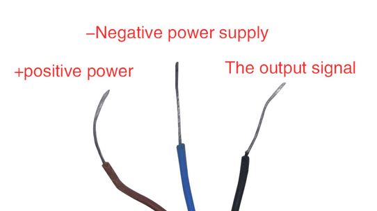
This OLED goes out to all the fans who want more pixels in a smaller size! Normally our 128x64 OLEDs are the biggest ones we've stocked that can use I2C. This one is a whopping 128x128 pixels in crisp monochrome.
This display is a petite 1.12" diagonal, but very readable due to the high contrast of an OLED display. This display is made of 128x128 individual white OLED pixels, each one is turned on or off by the controller chip. Because the display makes its own light, no backlight is required. This reduces the power required to run the OLED and is why the display has such high contrast; we really like these miniature displays for their crispness!
The driver chip, SSD1107 can communicate in two ways: I2C or SPI. The OLED itself requires a 3.3V and 12V power supply and 3.3V logic levels for communication. We include a 3.3V regulator and 12V boost converter, and all pins are fully level shifted so you can use with 3V or 5V devices!
If you are using I2C, we've included SparkFun qwiic compatible STEMMA QT connectors for the I2C bus so you don't even need to solder! Plug and play with any board that has a Qwiic or STEMMA QT connector for effortless prototyping and development. QT Cable is not included, but we have a variety in the shop.
This display, being 128x128 pixels, requires 128 * 128 = 2KB of SRAM just to buffer the display. So you can't use it with a small chip such as the Arduino UNO (ATmega328 or 32u4). Pick a microcontroller or microcomputer with 16KB+ RAM - a SAMD21, SAMD51, ESP, nRF52, Teensy, etc will do an excellent job. As long as you have I2C or SPI interface available, you're good to go - SPI will be much faster but I2C requires fewer pins.
We have both Arduino and CircuitPython support for this display chipset (SH1107).
Please note that OLED displays are made of hundreds of...OLEDs! That means each pixel is a little organic LED, and if it's kept on for over 1000 hours it'll start to dim. If you want to keep the display uniformly bright, please turn off the display (set the pixels off) when it isn't needed to keep them from dimming.
Revision History
- As of October 2023 – we've updated this PCB with Adafruit Pinguin to make a lovely and legible silkscreen - you may get the new PCB or the older version with vector fonts - both are identical other than the fancy silkscreen.
OLED Display Details:
- Diagonal Screen Size:1.12"
- Number of Pixels:128 × 128
- Color Depth:Monochrome (White)
- Module Construction:COG
- Active Area (mm):20mm x 20mm
- Pixel Size (mm):0.15 x 0.15 mm
- Duty:1/64
- Brightness ( cd/m2): 100 (Typ) @ 12V
- Display current draw is completely dependent on your usage: each OLED LED draws current when on so the more pixels you have lit, the more current is used. They tend to draw ~35mA or so in practice but for precise numbers you must measure the current in your usage circuit.
- Product Dimensions: 40.5mm x 30.5mm x 6.0mm
- Product Weight: 6.4g
What's in the box?
1 x Adafruit Monochrome 1.12" 128x128 OLED Graphic Display
Resources
Single-cell lithium base battery charger & protection module. The charging will be via a USB-C connector. Lithium base battery includes Li-po and Li-ion battery as the charging and discharging characteristic is similar.
The USB-C connector power input offers direct charging using widely available nowadays with power bank and also Android phone charger. With a maximum charging current of 1A, your battery can be charged faster and of course, do make sure the 5V input has sufficient power to provide more than 1A.
It comes with a TP4056 charging IC.
Using the module
- Connect USB-C cable for power, or 5V DC to pads marked IN+ and IN- on left-hand side of the module
- Connect cell to charge to B+/B- pads on right-hand side of module
- A load (something for the battery to power) can be connected to the OUT+/OUT- pads on the right-hand side
- Important! Disconnect load when charging
- The red LED indicates chaging in progress, green LED indicates charging has finished.
- Never charge your battery at a rate greater than 1C.
- Single Cell Lithium-based battery charger.
- USB-C connector for power input
- 5V input pads for DIY/custom input.
- Input Voltage: 5VDC
- Charging voltage limit: 4.2VDC
- Minimum discharge voltage: 2.5VDC
- Maximum discharge current: 3A
What's in the box?
1 x 1A LIPO Charger Module with Protection USB-C
DIY: Lithium 18650 Cells Charger by Using TP4056 Modules, in Instructables with video, by Well Done Tips
The liquid level sensor is equipped with an interface adapter that makes it compatible with DFRobot "Gravity" interface. The sensitivity can be adjusted via the potentiometer knob on the back of the sensor.
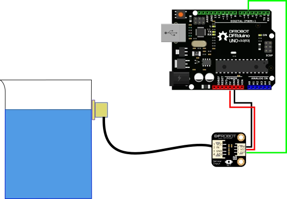
Specifications
- Operating Voltage (InVCC): DC 5 ~ 24 v
- Current consumption: 5 mA
- Output voltage (high level): InVCC
- Output voltage (low level): 0V
- Output current: 1 ~ 50 mA
- Response time: 500 ms
- Operating Temperature: 0 ~ 105 ℃
- Range for thickness of induction (sensitivity): 0 ~ 13 mm
- Humidity: 5% ~ 100%
- Material: ABS.
- Waterproof performance: IP67
- Dimension: 28 * 28 mm / 1.1 * 1.1 inches
What's in the box?
1 x Liquid Level Sensor Probe
1 x Liquid Level Sensor Adapter
1 x Gravity Digital 3-Pin Cable
Resources
Need a dependable 3.3V rail for your next microelectronics project without the hassle of designing a custom power circuit? The AMS1117-3.3V LDO Step-Down Power Module provides a rock-solid, low-noise voltage supply in an ultra-small footprint.
Unlike bare regulator chips that require manual calculation and soldering of external decoupling capacitors to prevent voltage ripple, this breakout board comes completely pre-assembled. It features dual-stage filtering capacitors pre-soldered directly to the PCB, ensuring your sensitive microcontrollers receive smooth, spike-free power right out of the box.
Designed for Rapid Prototyping
With standard 2.54mm (0.1") pitch pin headers, this buck-style module slots effortlessly into standard breadboards, stripboards, or female jumper wires. It also includes an integrated red LED power indicator, giving you instant visual confirmation that your circuit is active and receiving juice. It is an indispensable tool for powering modern IoT hardware that demands a clean 3.3V environment.
Key Features & Benefits
- Plug-and-Play Breakout: Skips the breadboard clutter. Includes onboard filtering capacitors for maximum voltage stabilization without extra components.
- 800mA Current Capacity: Delivers up to 800mA of output current—more than enough to handle the peak transmission spikes of power-hungry Wi-Fi and Bluetooth modules.
- Onboard Power LED: Features a bright, integrated red LED indicator for effortless power-state diagnostics.
- Breadboard Friendly: Pre-soldered with standard 4-pin row headers ($2.54\text{mm}$ pitch) for instant integration into prototyping environments.
- Safe & Stable: The underlying AMS1117 architecture includes built-in thermal shutdown and short-circuit current limiting protection circuitry.
Specifications
| Feature | Specification |
| Regulator IC | AMS1117-3.3 (Linear LDO) |
| Input Voltage (Vin) | DC 4.5V to 7.0V |
| Output Voltage (Vout) | DC 3.3V (+- 0.05V error margin) |
| Maximum Output Current | 800mA (Recommended continuous load: <400mA) |
| Pin Pitch | 2.54mm / 0.1" (Standard) |
| Module Dimensions | 25mm x 11mm (approx. 1" x 0.4") |
| Indicator | Onboard Red LED |
Pinout Configuration
The module features a simple, clearly labeled 4-pin interface (2 inputs, 2 outputs):
VOUT (+): Regulated 3.3V DC Output
GND (-): Common Ground / Negative Terminal
VIN (+): Unregulated Input Voltage (4.5V – 7V)
What's in the box?
1 x AMS1117-3.3V DC-DC Step-Down Power Module
Resources
Pro-Tips & Usage Notes for Makers
- Mind the Heat: Because this is a linear LDO regulator (not a switching buck converter), it drops excess voltage by converting it into heat. For continuous high-current applications (above 400mA) or when feeding it a maximum 7V input, ensure the module has decent airflow to prevent thermal throttling.
- Ideal Application: This is the gold standard companion module for dropping standard 5V USB power down to 3.3V to safely run an ESP8266 (NodeMCU), ESP32, Raspberry Pi Pico, or standard 3.3V I2C display panels.