
Special Offers


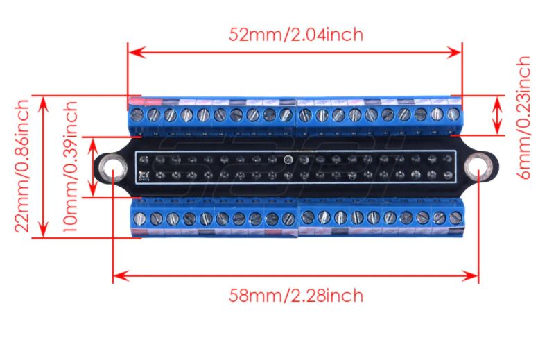
- Tiny size & solidly built
- Well made terminal block
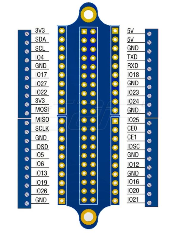
- Legible miniscule printing of the labels of each of the GPIO pin's function
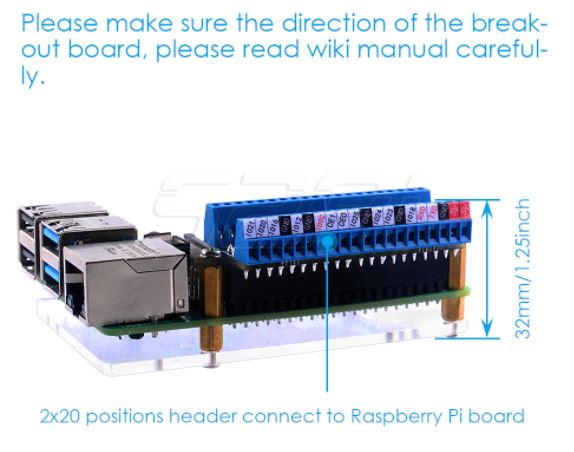
- Secure connection to the Raspberry Pi
What's in the box?
1 x Terminal block
1 x Screwdriver
1 x Acrylic board
2 x Nuts
2 x M2.5x11 brass standoffs
4 x M2.5x5 6 brass standoffs
6 x Screws
Resources
Wiki - Raspberry Pi GPIO Terminal Board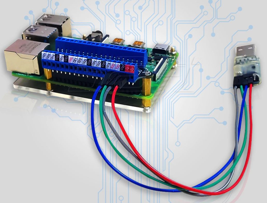
(* Raspberry Pi NOT included - ONLY GPIO screw terminal*)
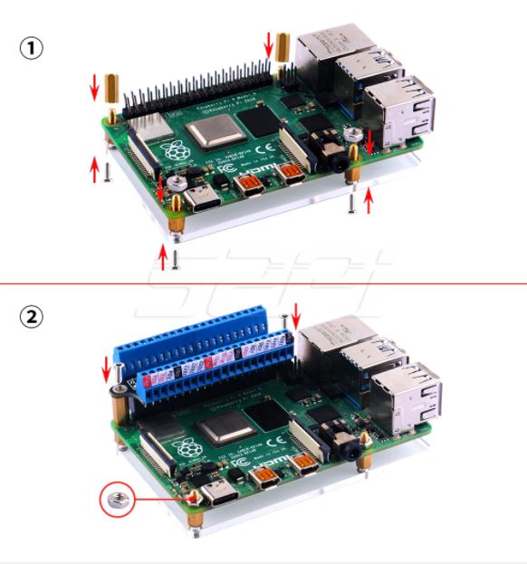
(* Raspberry Pi NOT included - ONLY GPIO screw terminal*)

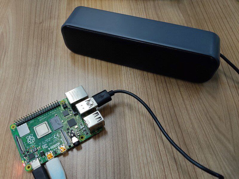
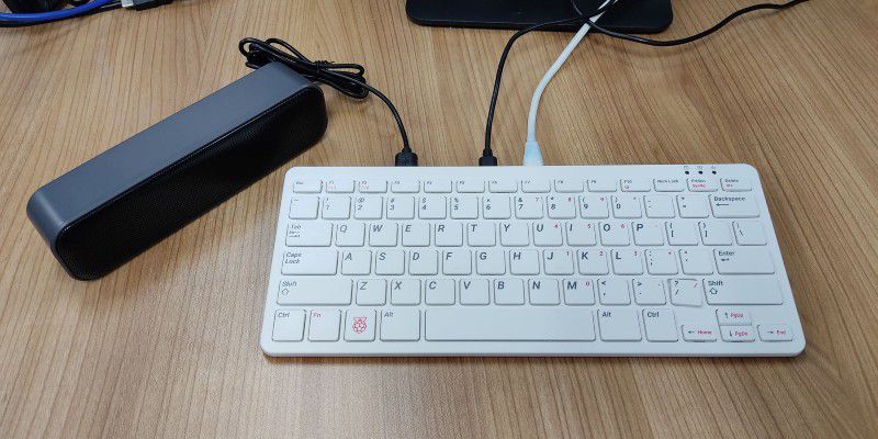
As the new Raspberry Pi 400 keyboard computer does not come with a 3.5mm Audio Barrel for speaker output, this USB powered, and signal is the perfect speaker for it. And we have tested it with Raspberry Pi 400, it works like expected. No driver is needed, plug and use!
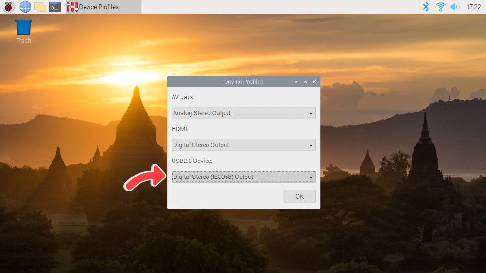
Note: If you're using the speaker with your Raspberry Pi, be sure to change the audio device to USB2.0 Device and change the output to Digital Stereo Output. Else, you will not be able to control the volume.
Features and specifications
- They are small and compact, so they can be brought anywhere.
- Powered by a single USB cable, have NO volume control knob, easy to use.
- Anti-interference and stereo sound.
- Crystal-clear treble.
- Space-saving design, they can be conveniently placed next to your PC monitors without compromising on valuable desk space.
- Built-in 2 speakers, balance and enhance the sound of your laptop, notebook, computer, PC, tablets, good for work, music, movies, games, etc.
- Acoustic quality stereo sound, let your room filled with music, movies, or computer games.
- No driver is needed for Windows, Linux and macOS, just plug and play!
- Great for
- Enhance any media experience while at home, office, kitchen, basement, or on the go.
- Upgrade to your computer's weakened or faint internal speakers. Perfect USB Speakers for Windows PCs, Desktop Computer, Laptop.
- Daily listening, static listening at home or office.
- Material: Plastic
- Output Power: 3W*2
- Channel: 2.0
- Frequency Response Range: 25Hz-20KHz
- Separation: ≥40dB
- Power Supply: USB 5V
- SNR: ≥80dB
- Voltage: 5V
- Connectivity: USB
- Number of speakers: 2
- USB Cable Length: 47 inches
- Connection radius: direct connection
What's in the box?
1 x 6W Stereo USB Power and Signal Speaker-Black
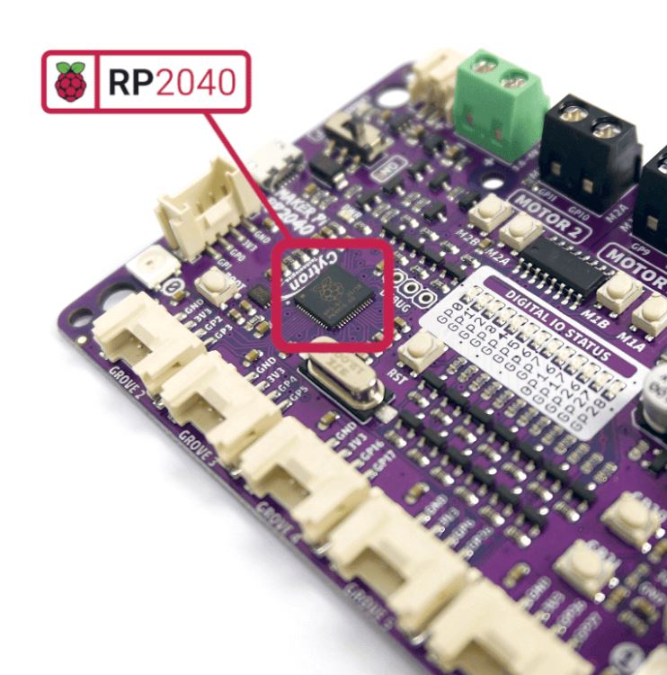
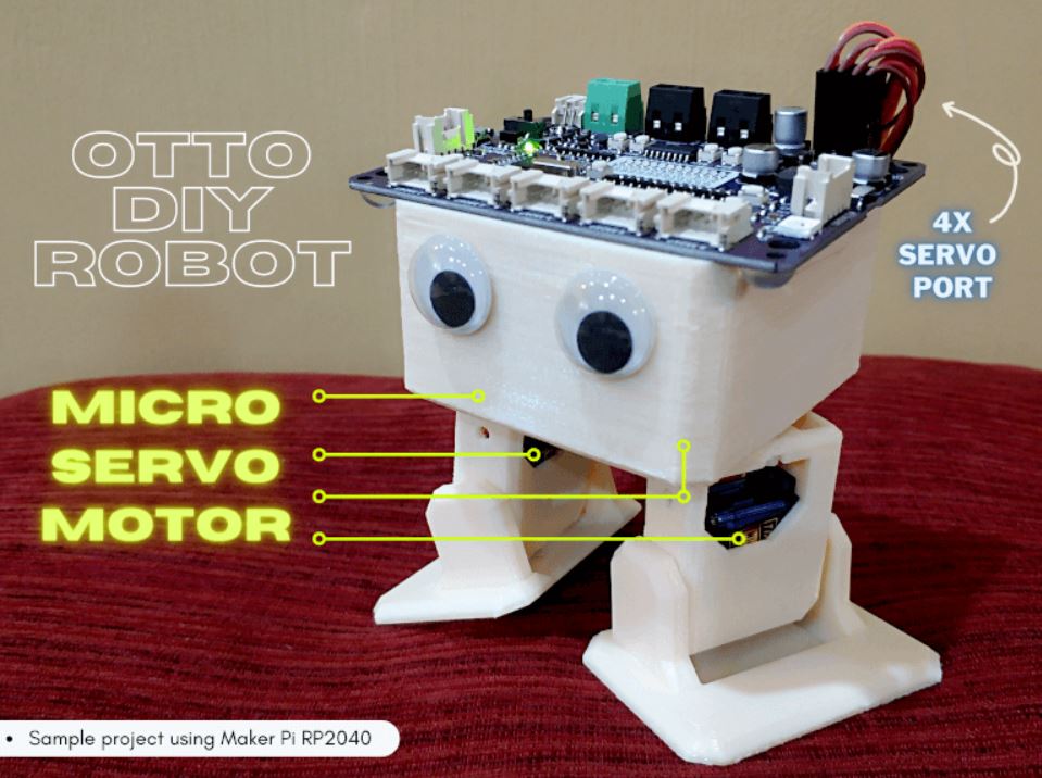
Cytron Maker Pi RP2040 features the first microcontroller designed by Raspberry Pi - RP2040, embedded on a robot controller board. This board comes with dual channel DC motor driver, 4 servo motor ports and 7 Grove I/O connectors, ready for your next DIY robot / motion control project. Now you can build robot, while trying out the new RP2040 chip.
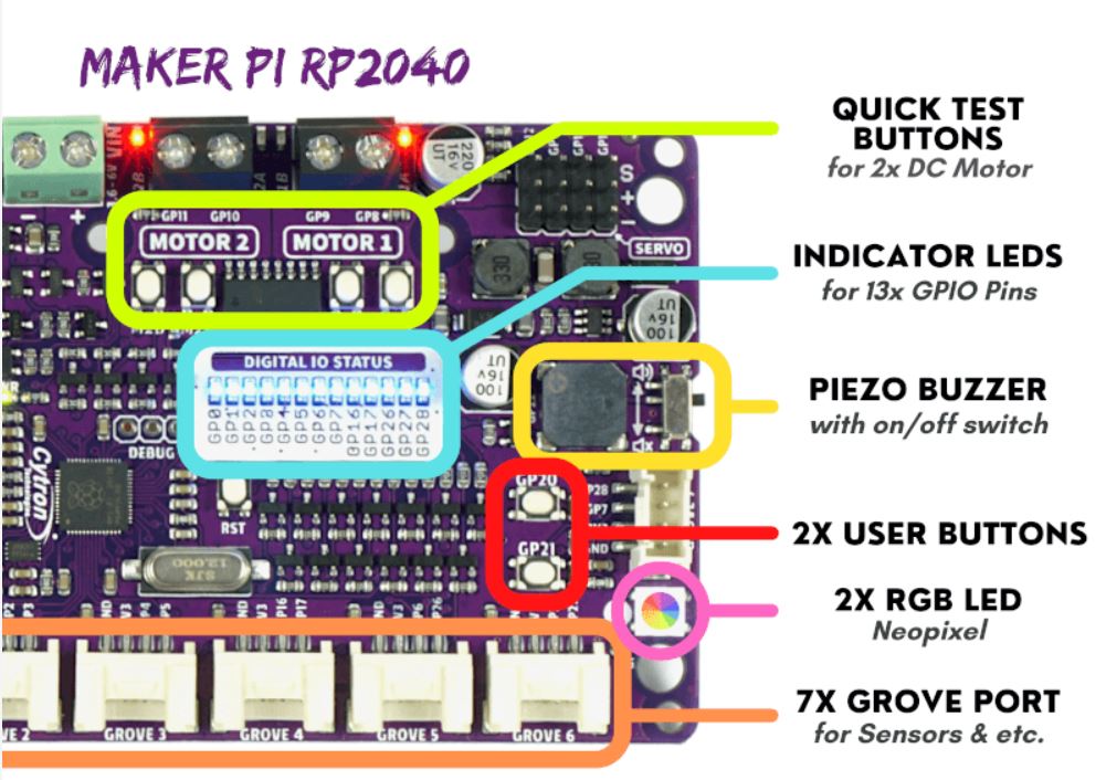
The DC motor driver onboard is able to control 2x brushed DC motors or 1x bipolar/unipolar stepper motor rated from 3.6V to 6V, providing up to 1A current per channel continuously. The built-in Quick Test buttons and motor output LEDs allow functional test of the motor driver in a quick and convenient way, without the need of writing any code. Vmotor for both DC and servo motors depends on the input voltage supplied to the board.
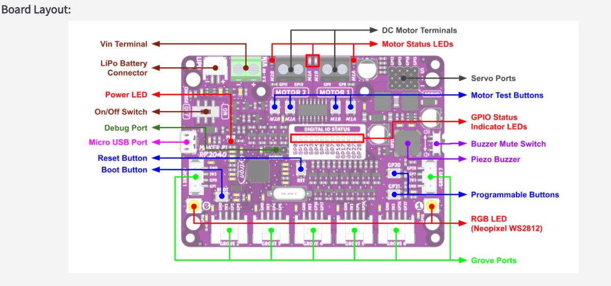
Features:
- Powered by Rapberry Pi RP2040
- Dual-core Arm Cortex-M0 processor
- 264KB internal RAM
- 2MB of Flash memory
- the exact same specifications with Raspberry Pi Pico
- Robot controller board
- 4x Servo motors
- 2x DC motors with quick test buttons
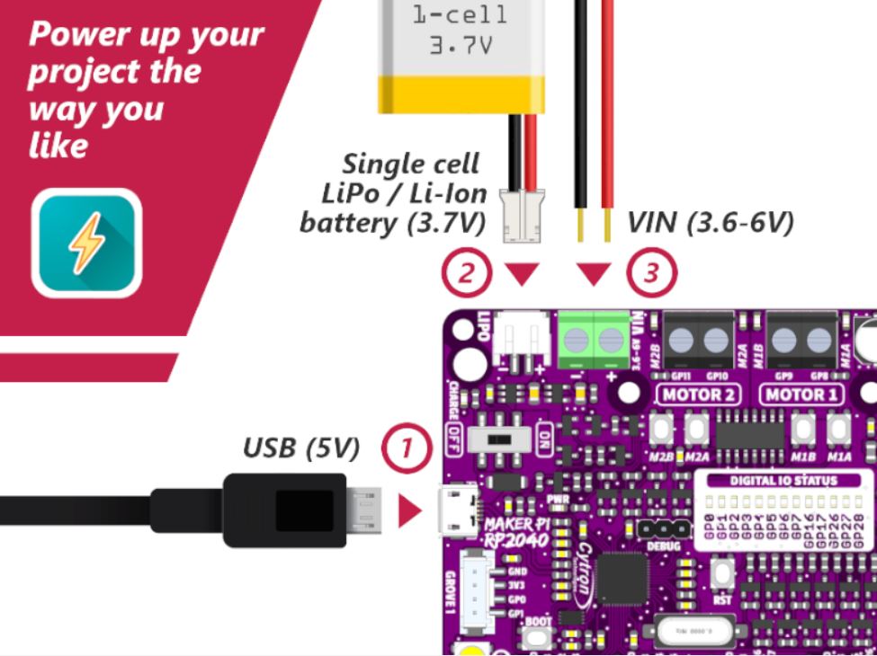
- Versatile power circuit
- Automatic power selection: USB 5V, LiPo (1-cell) or Vin (3.6-6V)
- Built-in 1-cell LiPo/Li-Ion charger (over-charged & over-discharged protection)
- Power on/off switch
- 13x Status indicator LEDs for GPIO pins
- 1x Piezo buzzer with mute switch
- 2x Push button
- 2x RGB LED (Neopixel)
- 7x Grove ports (flexible I/O options: digital, analog, I2C, SPI, UART...)
- Preloaded with CircuitPython by default
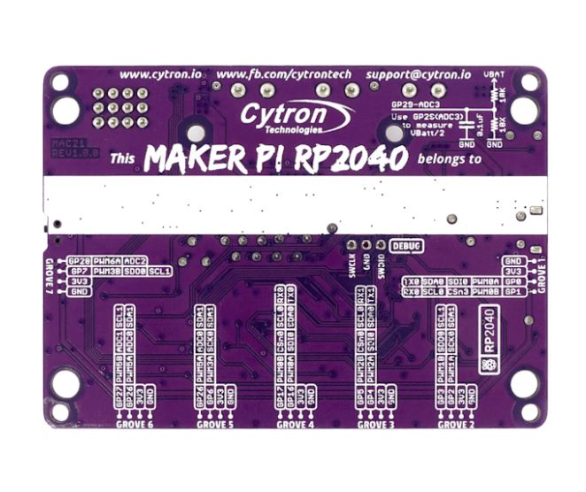
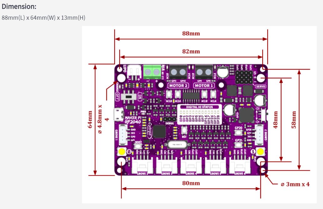
- Mouting holes
- 4x 4.8mm mounting hole (LEGO® pin compatible)
- 6x M3 screw hole
What's in the box ?
- 1x Maker Pi RP2040
- 4x Grove to Female Header Cable
- 1x Mini Screwdriver
- 1x Silicone Rubber Feet (Pack of 4)
Resources:
- Getting Started with Maker Pi RP2040 & Example Code
- Maker Pi RP2040 Datasheet
- Maker Pi RP2040 Schematic
- Maker Pi RP2040 VS. Maker Pi Pico comparison table
- CircuitPython for Maker Pi RP2040
- 3D CAD
- Getting Started with RP2040 (Raspberry Pi official page)
- RP2040 Datasheet
Powering the Maker Pi 2040
There are three ways to supply power to the Maker Pi RP2040 - via USB (5V) socket, with a single cell LiPo/Li-Ion battery or through the VIN (3.6-6V) terminals. However only one power source is needed to power up both controller board and motors at a time. Power supply from all these power sources can all be controlled with the power on/off switch onboard.
Maker Pi RP2040 features all the goodness of Cytron's Maker series products. It too has lots of LEDs useful for troubleshooting (& visual effects), is able to make quite some noise with the onboard piezo buzzer and comes with push buttons ready to detect your touch.
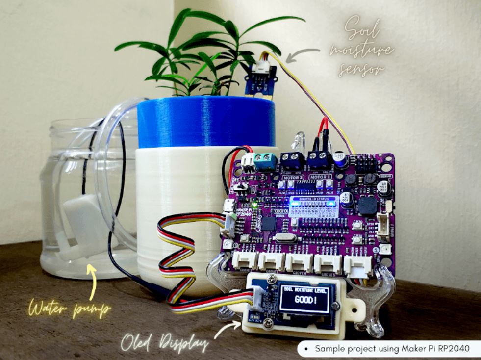
Simple Robotic projects done
(* Only includes the Maker board - All other contents are for idea / advertising purposes only*)
If you own an Arduino UNO R3, you might need this case/enclosure :) This is pretty simple yet practical casing designed for Arduino UNO. It offers plenty of inner space, and if you need to access the GPIO of Arduino UNO, the top cover has an opening for it. It is perfect casing for educator, beginner, or maker that need to access the GPIO. With its transparent color and build using ABS to provide rugged protection to your Arduino UNO.
The case comes in two parts so you can simply snap it together, no screws or nuts needed. There is a base plane, where you should place the Arduino UNO board. Arduino UNO fit into the base plane nicely, no screw is needed to secure the Arduino. The best part for this enclosure is you can access all the pins and ports on the Arduino UNO. This case suitable for Arduino Uno Rev3 and also Uno Compatible (CH340).
Note: If you want to use this case with Arduino Uno Rev3, you need to remove the base first before putting it into this case.
Features
- Protective case designed specifically for Arduino Uno R3.
- The case is a two-piece injection-molded that snaps together around for Arduino. Holds the board firmly in place.
- It provides tough protection for Arduino UNO while providing access to all connectors.
- Easy access to each header, USB port, power jack, the reset button, etc.
- Includes reset key for use with the Uno's reset button. Secondary screw-mounting points for securing for Arduino.
Note: Arduino UNO board not included in the packing list.
Specifications
- Colour: Transparent
- Material: ABS
- Product Size: Approx. 7.5cm x 6cm x 1.7cm
- Weight: About 25g
Note: Not Suitable to open and close the case frequently (Clip may break easily). It may be softer than normal ABS casing.
What's in the box?
1 x Enclosure for Arduino UNO - Transparent

Ring terminals connect two or more wires to a single connection point, by fitting the open face of the terminal over a stud. They create a solid connection as the ring that is fitted over the stud cannot come loose or fall off. This removes the possibility of the ring terminal disconnecting. They are widely known for the semi-permanent connections that they create. To make ring terminals even better, they can easily be used with two or more wires depending on the application. Ring terminals are the most secure type of tongue style terminal available and are commonly chosen for their durability, ease of use, and longevity in tough conditions.
Specifications
- Conductor cross section: 0.5-1.5 mm2
- Bolthole: 4mm
What's in the box?
1 x pack of 10 lugs
You will find our lugs selection here

Ring terminals connect two or more wires to a single connection point, by fitting the open face of the terminal over a stud. They create a solid connection as the ring that is fitted over the stud cannot come loose or fall off. This removes the possibility of the ring terminal disconnecting. They are widely known for the semi-permanent connections that they create. To make ring terminals even better, they can easily be used with two or more wires depending on the application. Ring terminals are the most secure type of tongue style terminal available and are commonly chosen for their durability, ease of use, and longevity in tough conditions.
Specifications
- Conductor cross section: 1.5-2.0mm2
- Bolthole diameter: 4mm
What's in the box?
1 x pack of 10 lugs
You will find our lugs selection here

Joiner Terminals are a type of connector used to attach a wire or wires to a stud, bus bar, or another part of an electrical system.
These Lugs are insulated to ensure safe and secure connections to an electrical device.
Specifications
Conductor cross section: 1.5-2.5 mm2
What's in the box?
1 x pack of 10 lugs
You will find our lugs selection here

Specifications
- 24 Gigabit LAN ports for high-speed wired connections
- Plug-and-play installation for convenience
- Auto-negotation on all ports
- Half/full-duplex, auto MDI/MDIX, and store-and-forward switching
- Full wire-speed data transmission
- Energy-efficient design
What's in the box?
1 x D-Link DGS-1024C switch

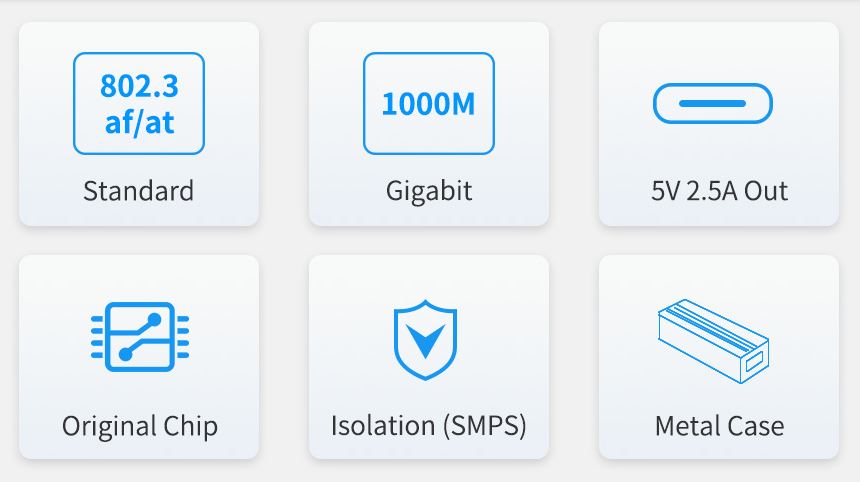
Features at a glance
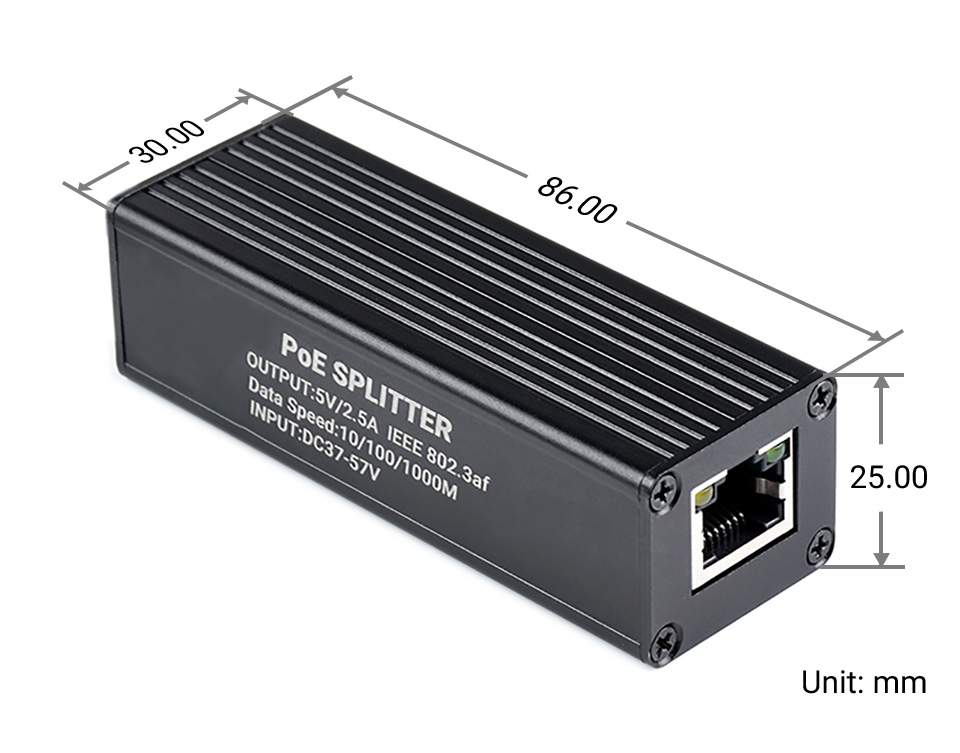
- Incorporates original chip Si3404, high-efficiency, high-safety, stable-performance
- 10/100/1000Mbps auto-negotiation Ethernet port
- 802.3af/at-compliant PoE (Power over Ethernet) standard
- Isolated SMPS (Switching Mode Power Supply), effectively protecting the powered device
- 5V DC output, suitable for powering Raspberry Pi and other small-scale network devices
- Black dull-polish metal case, sturdy and rugged, higher protection level, better heat dissipation
Specifications
| Power supply | supports 1/2(+); 3/6(-); 4/5(+); 7/8(-) powering |
|---|---|
| PoE input voltage | 37V ~ 57V |
| Type-C output | 5V 2.5A (MAX) |
| Cable | Cat-5 UTP |
| Standard | IEEE 802.3 af/at PoE Ethernet |
| Data rate | 10/100/1000Mbps |
| LED indicator | PoE power input indicator |
| Dimensions | 86 × 30 × 25mm (l × w × h) |
| Operating temperature | -40℃ ~ 85℃ |
Original chip solution
Incorporates Si3404, high-integration, high-efficiency, more safe and reliable
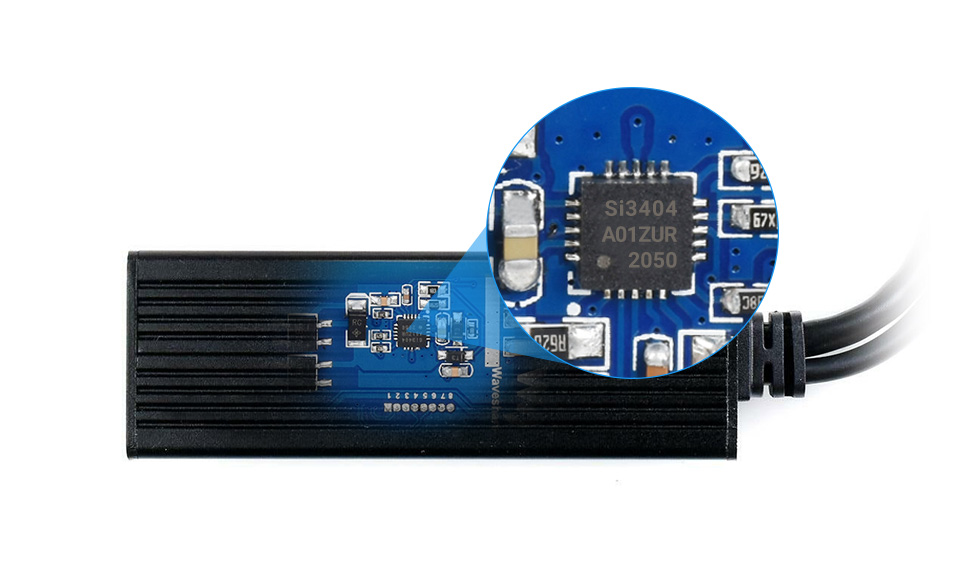
Isolated circuit protection, effectively protecting the powered device
Industrial grade protection case
aluminum alloy case, sturdy and rugged, higher protection level, better heat dissipation 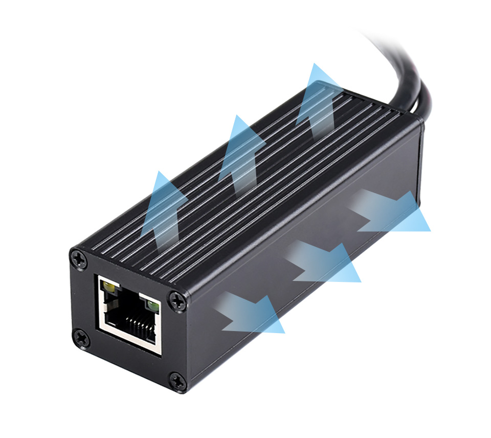
Powering the Raspberry Pi or other 5V-powered network devices by PoE switch
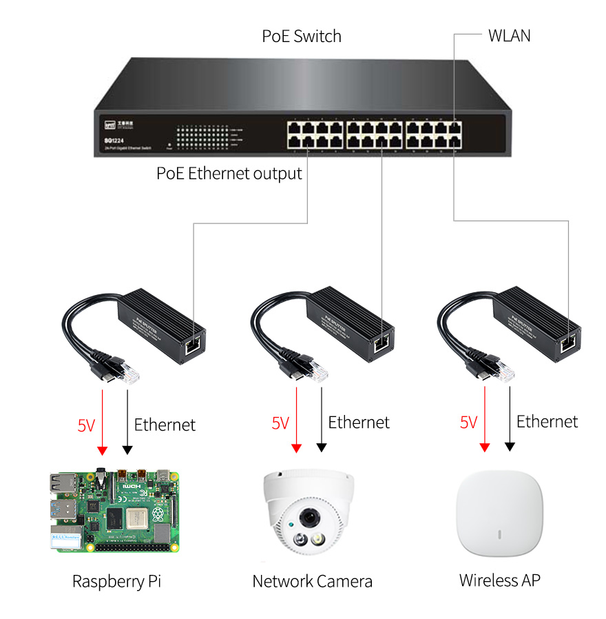
for reference ONLY, Raspberry Pi and switch are NOT included.

Specifications
- Brand: CHANZON
- Lens Size: 5mm Diameter
- Lens: Colour Lens
- Emitting Colour: Green Flash
- Viewing Angle: 20 Degree (Colour Lens)
- Forward Voltage: 3.0-3.2V
- Current: 20mA
- Frequency: 1.5HZ
- Flicker Frequency: 90 Times / Minutes
- Polarity: Anode (Longer Leg) | Cathode (Shorter Leg)
What's in the box?
10 x Flashing LEDs

Specifications
- Brand: CHANZON
- Lens Size: 5mm Diameter
- Lens: Colour Lens
- Emitting Colour: Red Flash
- Viewing Angle: 20 Degree (Colour Lens)
- Forward Voltage: 3.0-3.2V
- Current: 20mA
- Frequency: 1.5HZ
- Flicker Frequency: 90 Times / Minutes
- Polarity: Anode (Longer Leg) | Cathode (Shorter Leg)
What's in the box?
10 x Flashing LEDs

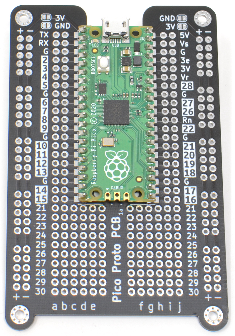
If you done using a breadboard for Pico and are ready to take your prototype to solder, you will love this board.
It can be tricky to work out which pin is which when using a Raspberry Pi Pico
with prototyping board. The MonkMakes Pico Proto PCB solves this problem by
labeling the Pico pins on the PCB.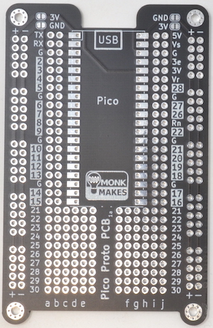
The MonkMakes Pico Proto PCB makes it easy to make soldered prototypes using the Raspberry Pi Pico. You can solder the Pico to the prototyping board using the castelations around the edge of the board, or using header pins, or even solder header sockets onto the Pico Proto PCB so that you can easily swap out the Pico.
Specifications
The layout of the Pico Proto PCB is modelled on a 400-point breadboard, and after the Pico is soldered to the PCB, there are 10 more rows, that can be used for through hole components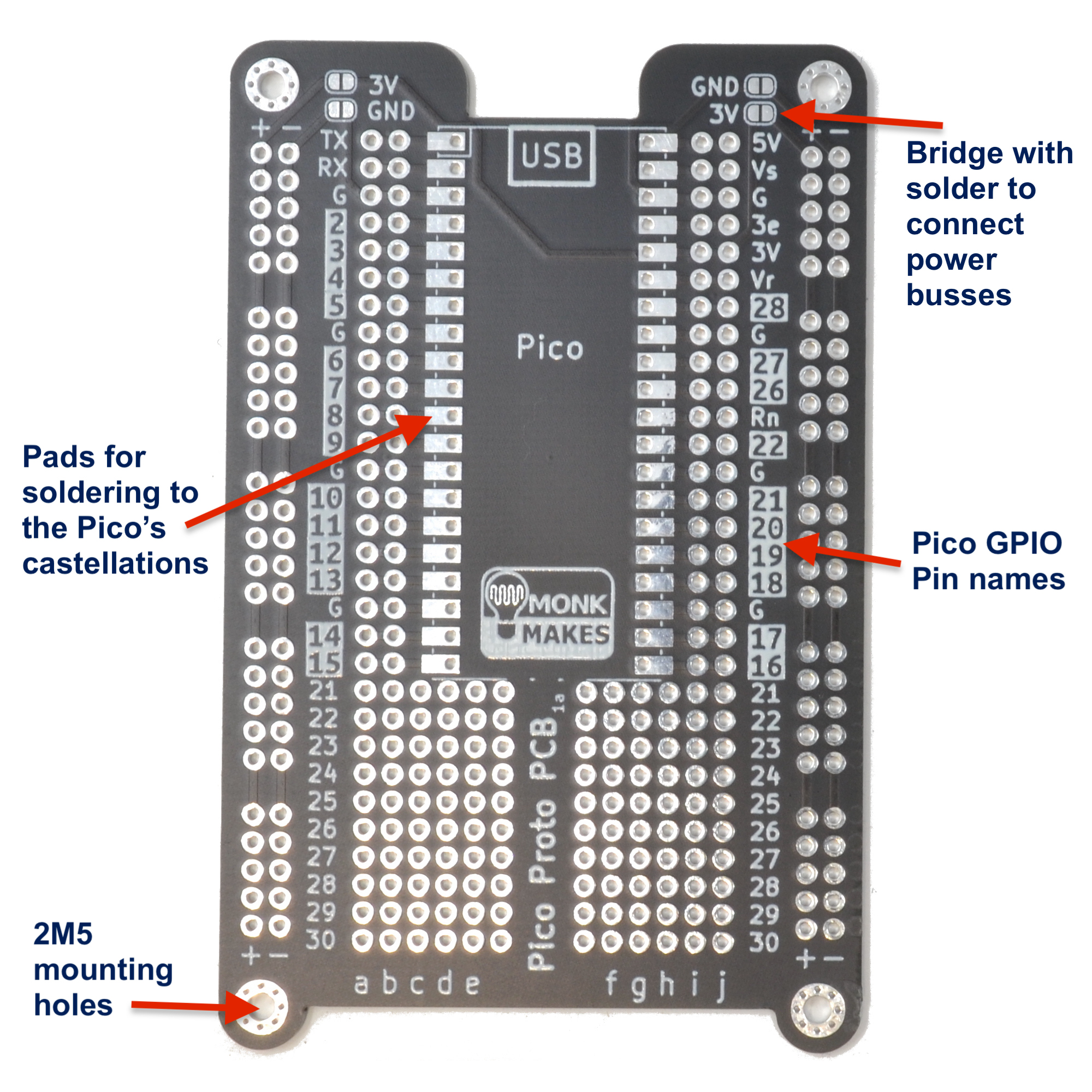
WARNING: Low voltage, low current usage only. Maximum 50V at 3A.
What's in the box?
1 x Pico Proto PCB
Resources
Instructions

Pictures are for reference only
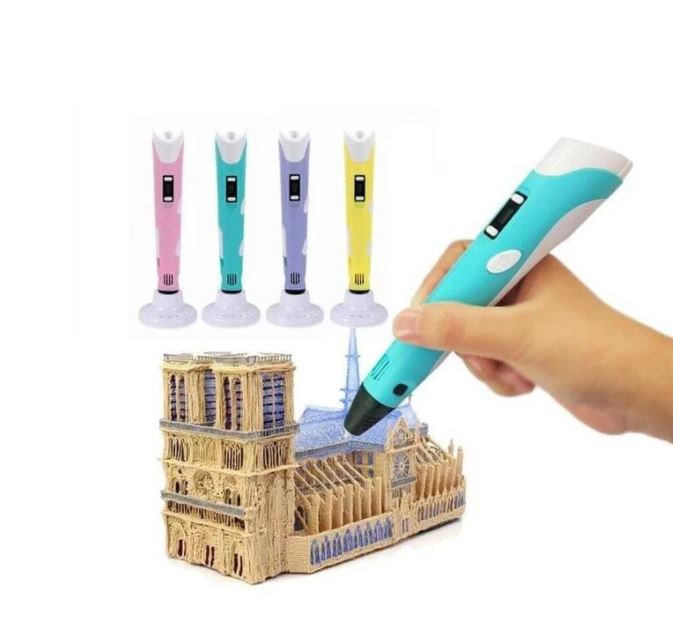
Have some fun with this 3D printing pen, this 3D printing pen is also suitable and safe for kids. They can now develop their hands-on skills and mental development ability.
By using the 3D pen can actually help kids developing their artistic skills, spatial thinking, and can be a great creative outlet that engages their minds as they create. Besides, this 3D printing pen has a stable performance. It is more stable, safe and reassuring. Let your child fall in love with 3D printing.
Specifications
- Electrical Parameter: 5VDC 2A
- Comes with a USB cable. Can be charged and used remotely.
Note: A power adapter is NOT included. - Can be used everywhere
- 3D printer for hand use
- Compatible with ABS and PLA filaments
- Diameter of filaments: 1.75mm
- Nozzle diameter: 0.7mm
- Heating Temperature: 160ºC - 210ºC (PLA), 210ºC - 235ºC (ABS)
- LCD for display filament type and temperature
- Adjustable filament feeding speed
- Ergonomic design, lightweight design, easy to operate
- Dimensions: 184mm x 31mm x 46mm
What's in the box ?
1 x 5V 3D Pen V2 with PLA Filament - Yellow
1 x 3D Printing Pen stand
1 x USB cable
1 x Packet filament (3 random colors, 3 meters in total)
1 x User Manual/Operation Instruction
Check this link out to see what some people come up with :
3D printing pen
Want to print a spool holder that clips onto your 3D pen?
Check out Thingiverse
This device allows you to store and use lengths of 1.75mm filament for a 3D pen. The unique mini spool is designed to prevent the filament from unraveling under its own spring tension. The parts can be welded together with your 3D pen.

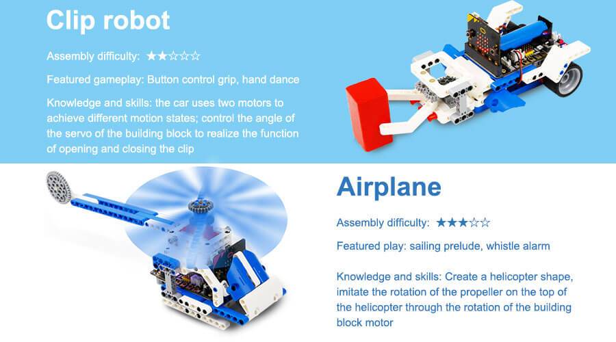
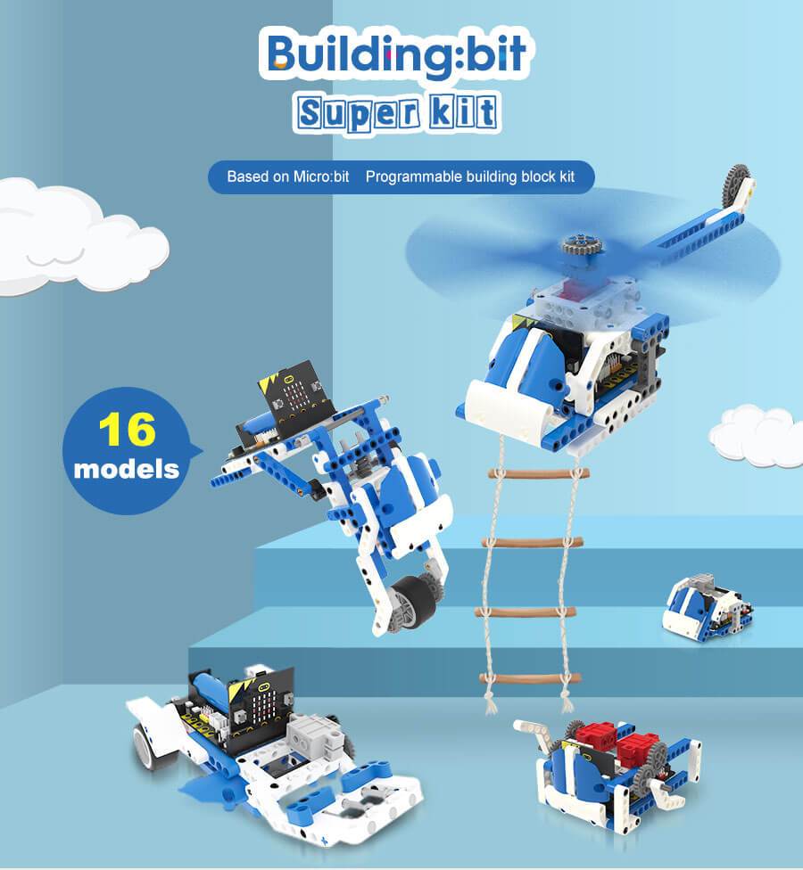
16 in 1 Building:bit Programmable Building Block Kits
The Building:bit comes with the Super:bit Expansion board and it works with both micro:bit V1 and micro:bit V2(micro:bit not included)
16-in-1 superkit programmable building block kit is designed based on BBC micro:bit, which is composed of Super:bit expansion board, building block servo, Building block motor, battery, and 358 building block parts.
We combine building blocks with electronic devices to bring your building blocks to life, and they can also play music and realize colorful lights. On the one hand, it allows children to learn to program. On the other hand, it can also cultivate children's practical ability and stimulate creativity by assembling building blocks.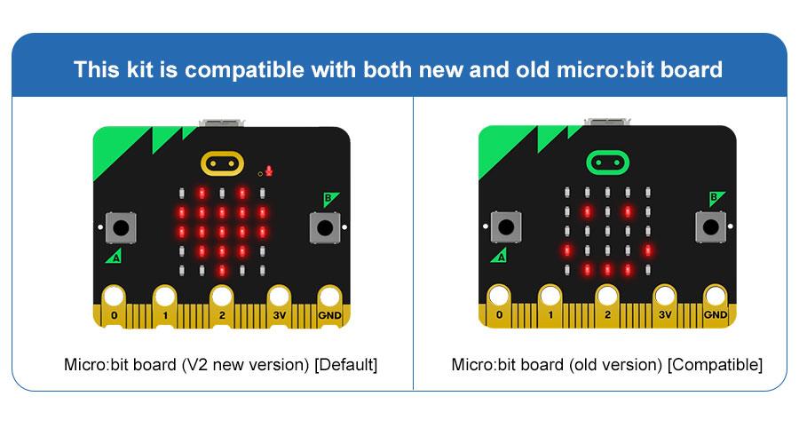
Features
- Compatible with both micro:bit V1.X and V2.
- The building:bit kit is designed based on BBC micro:bit, equipped with Super:bit professional expansion board.
- The most popular microcontrollers for children are suitable for STEAM education.
- Super:bit expansion board specially designed for micro:bit can perfectly integrate with building blocks, build any shape, and drive building block servo, motor, RGB lights and other devices.
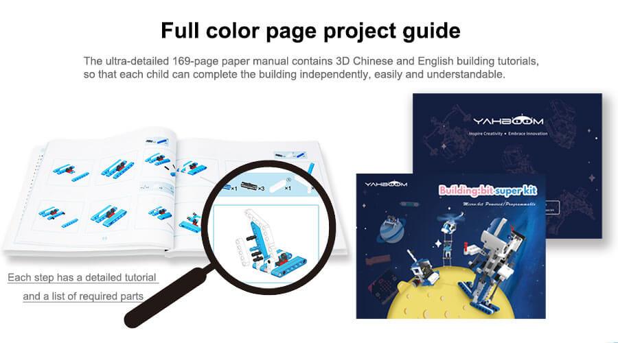
- 16 kinds of building block models full-color printing project instruction manual
- The building block parts of this kit are dominated by blue and white, the whole is full of science and technology, which can be assembled into N models.
- The manual includes assembly steps of 16 kinds of models and basic instruction content for programming.
- MakeCode programming Python programming, suitable for users of different ages.
- MakeCode programming: It can effectively reduce the learning threshold and improve children's interest in learning by dragging and splicing colorful building blocks
- Python programming: A string of character commands control the building blocks, writing a wonderful chapter belonging to the Makers and building block enthusiasts.
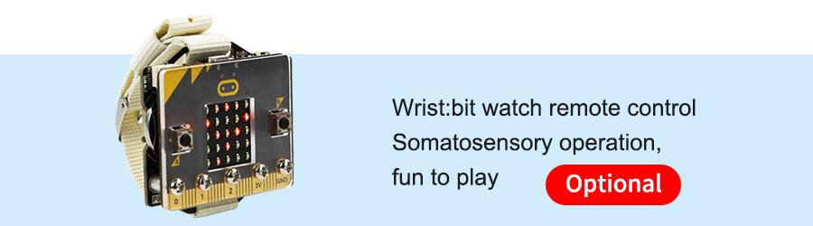
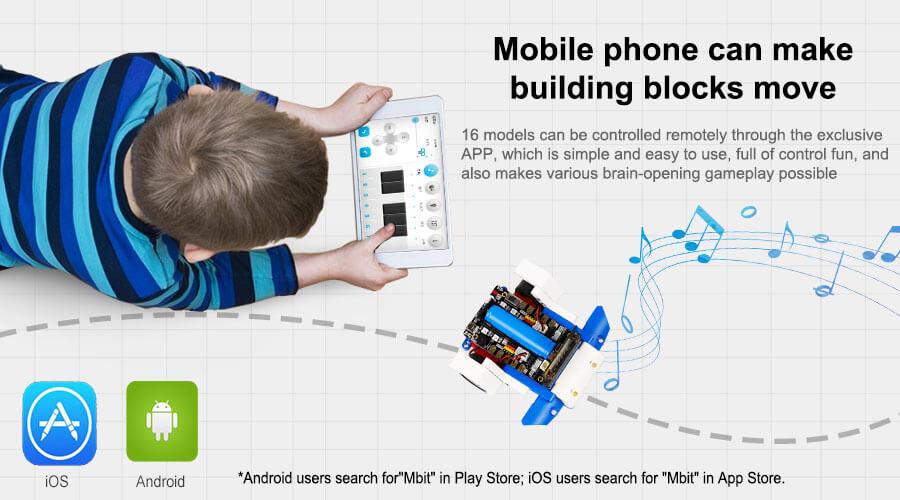
- Support App/game handle remote control
- When using different equipment to interact with the building blocks, the user can experience the fun brought by technology.
- Compatible with Lego building block, various gameplays
- 16 kinds of models with up to 80 gameplays, such as spider walking, helicopter propeller rotation, car wriggling, cannonball shooting, etc.
- Users can also expand through more Lego bricks and build more interesting shapes.
- Programming language: MakeCode graphical programming / Python programming

Specifications
- Remote control method: APP/micro:bit gamepad
- Main material: ABS
- Package Weight: about 1400g
- Packing box size: 288 * 213 * 68mm
- Battery type: Rechargeable lithium battery
- Lifetime: 120 minutes
- Battery energy: 3.7V / 1200mAh
- Working temperature: 4 ~ 40 ℃
- Onboard function: RGB lights, buzzer, etc.
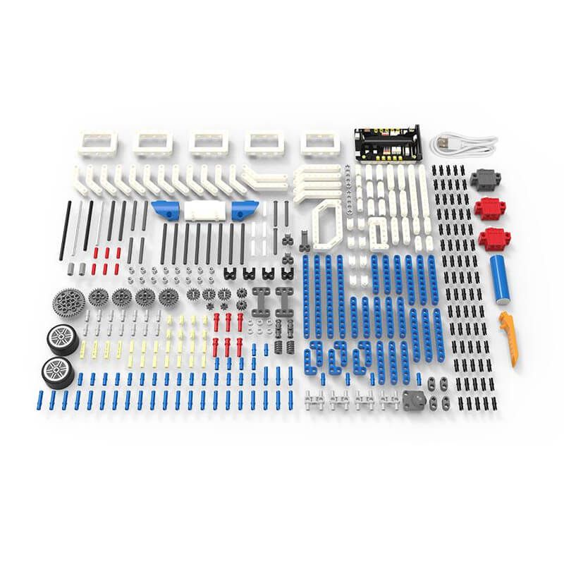
- Number of building blocks: 358 high-precision building blocks
- Motor / Servo: 2 motors, 1 servo
What's in the box?
1 x 16 in 1 Building:bit kit
Resources
- Yahboom Building:bit superkit tutorial
- Superbit hardware interface manual, pdf file
- APP(Android) download
- Bluetooth communication protocol, pdf file
- Assembly Instructions, zipped file, extract to get jpeg files
- Makecode offline software

Discover the true potential of Raspberry Pi with the new, official Handbook 2023. With over 200 pages of amazing projects, fun tutorials, practical guides, and clear reviews, it has everything you need to master Raspberry Pi!
Inside The Official Raspberry Pi Handbook 2023
- QuickStart guide to setting up your Raspberry Pi computer
- Make stuff with Raspberry Pi Pico W
- Incredible projects built by the global Raspberry Pi community
- Find the right kit and products for your dream builds
- Get creating with our comprehensive tutorials and guides
- Over 200 pages of essential advice!
1 x RPi 2023 Handbook

From the makers of Digital SLR Photography magazine, The Essential Guide To Landscapes is the complete guide to shooting your best ever landscape images. It’s 164 pages of essential photo technique, expert advice, and inspiration.

From learning the basics through to more involved techniques, The Essential Guide To Landscapes is packed with expert advice, photo workshops, and stunning photography to help photographers of all levels achieve their best ever results.
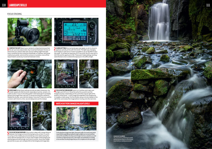
• Achieve maximum levels of image quality and detail
• Master camera controls and shoot like the pros
• Essential photo kit: our pick of the best ND filters and carbon tripods
• Location workshops, composition and lighting, coastal landscapes, and more!

What's in the box?
1 x Guide to landscapes photography book
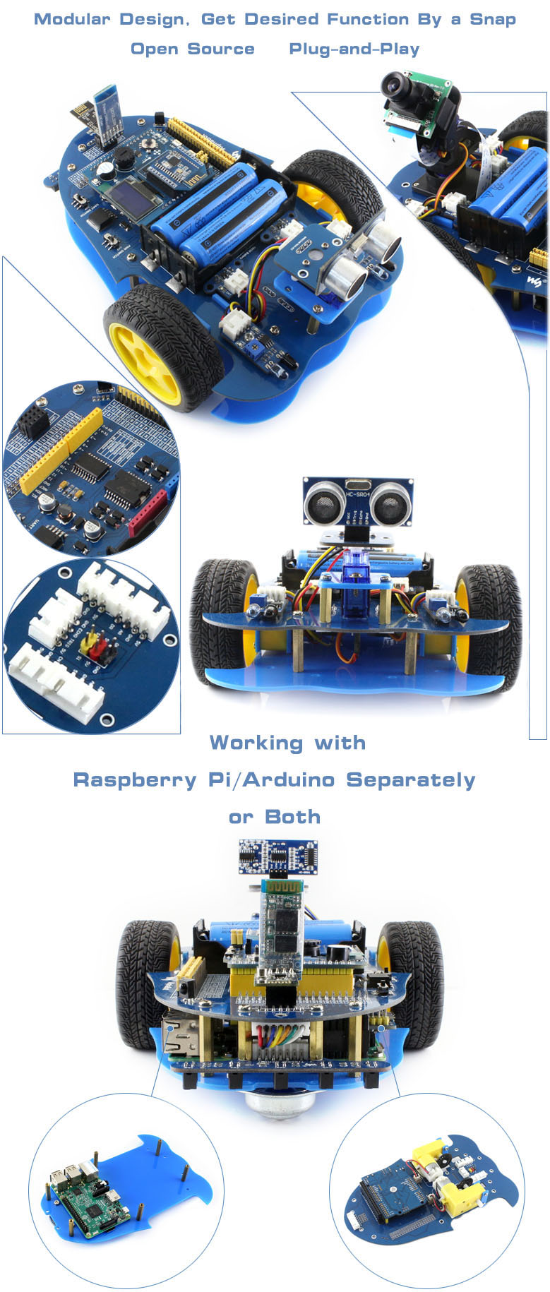
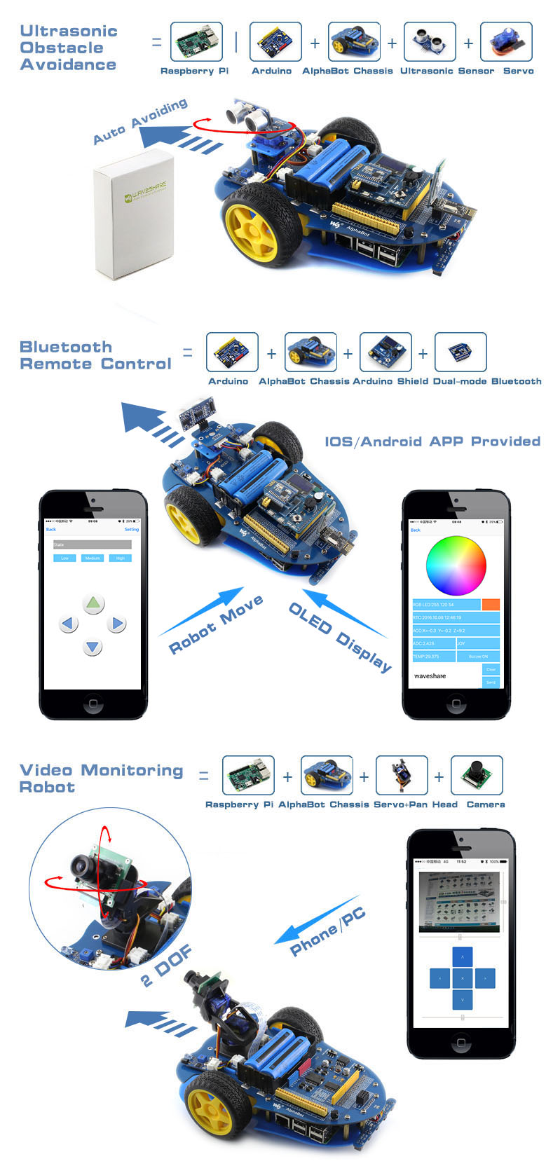
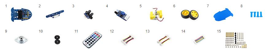
AlphaBot is a robotic development platform compatible with Raspberry Pi and Arduino. It consists of the AlphaBot mainboard, the mobile chassis, and everything required to get it moving.
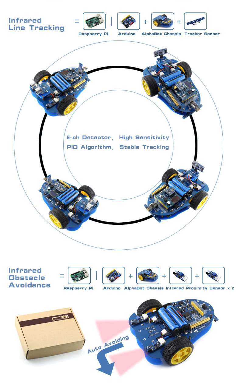
Just connecting a controller board, Raspberry Pi or Arduino, and combined with our open source example code, now it's all ready to start your robotic exploration: line tracking, obstacle avoidance, video monitoring, WiFi/Bluetooth/ZigBee/Infrared remote control, etc.
- Raspberry Pi/Arduino interfaces, works with either one separately, or both
- Arduino extend header, supports Arduino shields
- Modular design, plug-and-play modules like line tracking, obstacle avoidance, speed measuring, etc. eliminating the trouble of connecting mess wires.
- LM298P motor driver with diode protection circuit, more safety
- LM2596 voltage regular, provides stable 5V power to the Raspberry Pi/Arduino
- TLC1543 AD acquisition chip, allows the Pi to use analog sensors
What's on the AlphaBot Mainboard
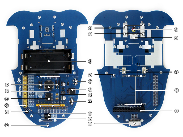
- Raspberry Pi interface: for connecting Raspberry Pi
- Arduino interface: for connecting Arduino
- Motor interface
- Ultrasonic module interface
- Servo module interface
- Obstacle avoidance module interface
- Speed measuring interface
- Battery holder: supports 18650 batteries
- Reserved power input (not soldered): for connecting other external power supply
- Arduino expansion header: for connecting Arduino shields
- UART interface: for connecting Bluetooth module, to control the robot remotely via Bluetooth
- SPI interface: for connecting NRF24L01 wireless module
- Line tracking module interface
- TLC1543: 10-bit AD acquisition chip, allows the Pi to use analog sensors
- LM298P: dual H bridge motor driver chip, up to 2A current
- Anti-reverse diode
- Power switch
- LM2596: 5V regulator
- Power indicator
- UART switch: turn on to enable serial communication between Raspberry Pi and Arduino
- IR receiver: control the robot remotely via infrared
- Raspberry Pi/Arduino selection: select the Raspberry Pi or Arduino to control the robot peripherals
What's in the box?
Please note that the battery length SHOULD be less than 67mm, some batteries with protection plate in the market are NOT supported
- AlphaBot mainboard x1
- Tracker Sensor x1
- Photo Interrupter Sensor x2
- Infrared Proximity Sensor x2
- Motor with gearbox 2PCS x1
- AlphaBot wheel 2PCS x1
- AlphaBot acrylic chassis x1
- Motor mounting plate 4PCS x1
- omni-direction wheel x1
- 20-slots encoder disk 2PCS x1
- IR remote controller x1
- XH2.54 4cm 4Pin 2PCS x1
- XH2.54 4cm 3Pin 2PCS x1
- XH2.54 4cm 7Pin x1
- AlphaBot screws x1
Resources

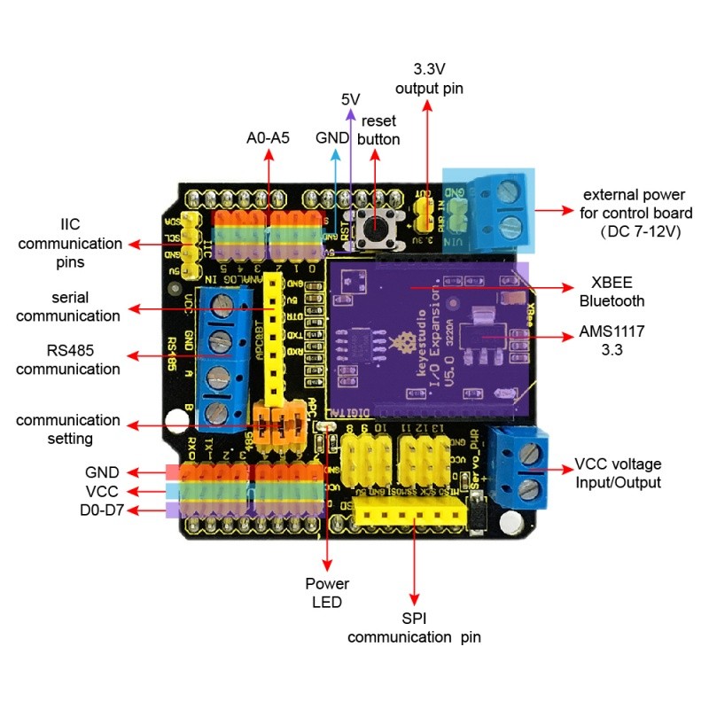
You can change the communication way via the jumper cap on the shield. If all the three jumpers are connected to APC, the shield will realize the XBEE Bluetooth communication. If all jumpers are connected to 485, realize the RS485 communication function.
Onboard also comes with a reset button, a D13 indicator, and some common communication pins of 2.54mm pin pitch, such as serial port, IIC, and SPI communication pins.
Besides, it also has two 2pin terminal blocks. One is VIN GND terminal block, used to supply the external power for the UNO R3 control board, with an input voltage of DC 7-12V. The other is the Servo_PWR terminal block, used for VCC voltage input/output. If not connecting the external voltage, supply 5V for the shield; if connecting the external voltage, VCC voltage is actually the external input voltage.
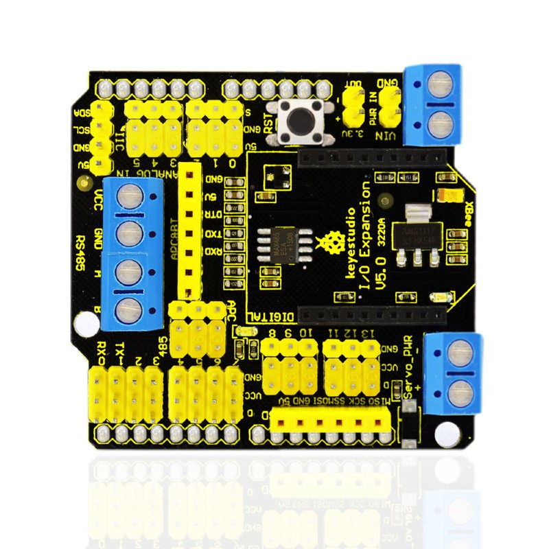
- Compatible with Arduino UNO R3.
- Comes with 14 digital input/output pins.
- Comes with 6 analog IO pins
- Onboard comes with a digital port power terminal block
- Comes with an external power input terminal block and a input contact pin ( power on the control board with DC 7-12V)
- Comes with an RS485 interface.
- Comes with a reset button
- Comes with a D13 indicator
- Comes with a XBEE Bluetooth interface
- Can connect three jumper caps (APC and 485) to switch the XBEE Bluetooth communication or RS485 communication.
- Comes with I2C, serial port and SPI communication pins
- Onboard comes with a DC 3.3V output pin
- Dimensions: 58.5mm x 57.5mm x 20mm
- Weight: 26.2g
Pinout diagram
1 x XBEE Shield with RS485 for Arduino UNO
Resources
Product wiki page

Note: the CM4 is NOT included. Please buy it separately if necessary.
The Nano Base Board (B) For Raspberry Pi Compute Module 4, is the Same Size As The CM4 and is suitable For Evaluating The Raspberry Pi CM4 Or Being Integrated Into End Products.
This module is Compact, Yet Complete, featuring: Standard CM4 Socket, 40PIN GPIO, Gigabit Ethernet, USB2.0, DSI, CSI, 3.5mm Audio Jack...
Specifications
CM4 SOCKET - suitable for all variants of Compute Module 4
NETWORKING - Gigabit Ethernet RJ45 connector
CONNECTOR - Raspberry Pi 40PIN GPIO header × 1
USB - USB 2.0 Type A connector × 1
DISPLAY - MIPI DSI port × 1 (15pin 1.0mm FPC connector)
CAMERA - MIPI CSI-2 port × 1 (15pin 1.0mm FPC connector)
VIDEO - Mini HDMI port × 1, supports 4K 30fps output
AUDIO - 3.5mm jack
STORAGE - Micro SD card socket for Compute Module 4 Lite (without eMMC) variants
POWER INPUT - 5V
DIMENSIONS - 56 × 41mm
What's On Board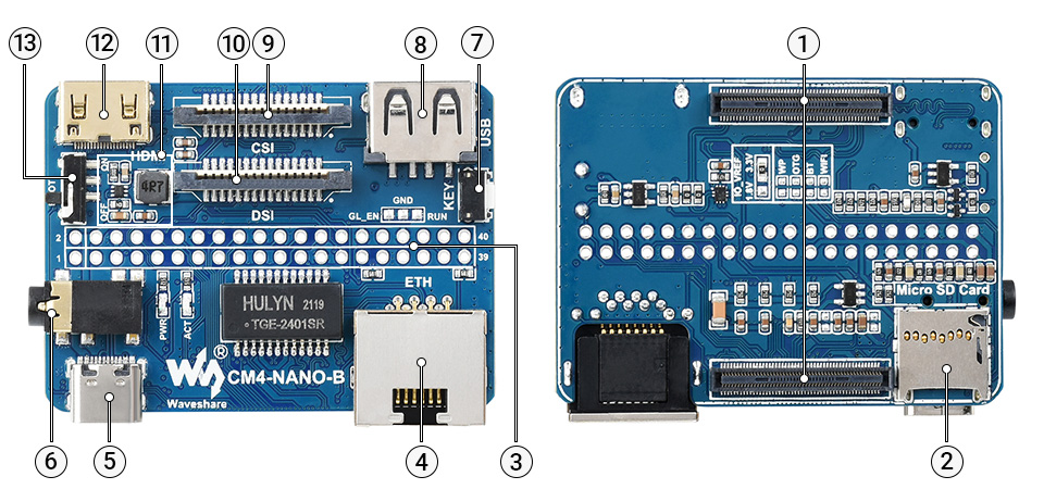
- CM4 socket
suitable for all variants of Compute Module 4 - Micro SD card slot
for connecting a Micro SD card with pre-burnt image (Lite variant ONLY) - 40PIN GPIO header
for connecting sorts of HATs - Gigabit Ethernet RJ45 connector
- Power supply / Programming
5V power supply, or used for eMMC burning - 3.5mm audio jack
- User button
- USB2.0 connector
for connecting sorts of USB devices
- CSI connector
MIPI CSI camera interface - DSI connector
MIPI DSI display interface - MP1658
- Mini HDMI connector
supports 4K 30fps output - BOOT switch
ON: Switch USB to Type C interface, will enter download mode when powered on (configured as a large-capacity disk through RPI boot)
OFF: Switch USB to Type A interface, will not enter download mode when powered on (booted from eMMC or Micro SD card)
Outline Dimensions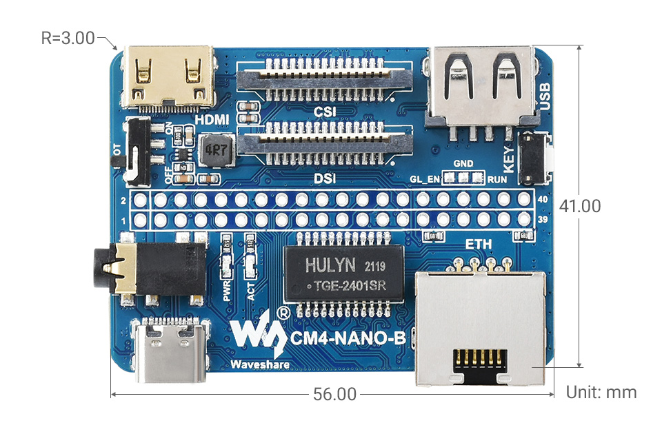
What's in the box?
1 x CM4-NANO-B

1 x 2*20PIN color-coded straight pin header

Resources
WIKI: CM4-NANO-B

This lovely little lens set is the best way to easily expand the field of view of your Raspberry Pi camera!
This lens kit means that you can use your camera module in many exciting ways:
- 1x Wide-angle lens: Ideal for capturing those landscape shots/night sky time-lapses
- 1x Macro lens: Beautiful close-up images of anything from insects to circuit boards
- 1x Fish-eye lens: Security systems and crazy 180° FOV shots
Perfect for taking shots from anywhere from your desk to the edge of space this lens comes with a back splint which means you can also use it with other camera devices such as your mobile phone.
Each lens screws into the clip which fits perfectly onto your camera module.
Features
- Compatible with the known universe *
- High-class glass lens, high clarity.
- No *vignetting or dark circle.
- Lens covers to protect the camera lenses
- Material: ABS & aluminum alloy
- Compatible with most of the official Raspberry Pi Camera Modules
* Vignetting is a phenomenon in which the corners of an image appear darker than the center due to the blocking or shading of light rays by external objects or the physical dimensions of a lens
What's in the box?
1 x camera clip
3 x screw on lenses
Please note: The third lens isn't missing; it’s actually screwed into the second lens.