
Search
Search Criteria
Products meeting the search criteria
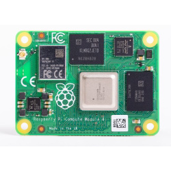


Raspberry Pi Compute Module 4 IO Board (CM4 IO board)
PLEASE NOTE: The Compute module 4 board is not included

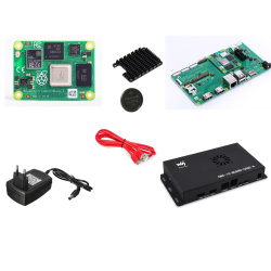
Raspberry Pi Compute Module 5 IO Board (CM5 IO board)
PLEASE NOTE: The Compute module 5 board is not included


