
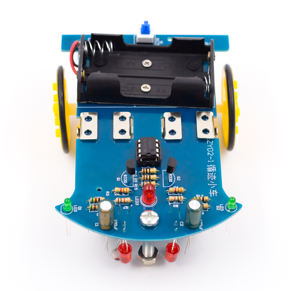
Tracking Robot Car Electronic DIY Kit With Reduction Motor
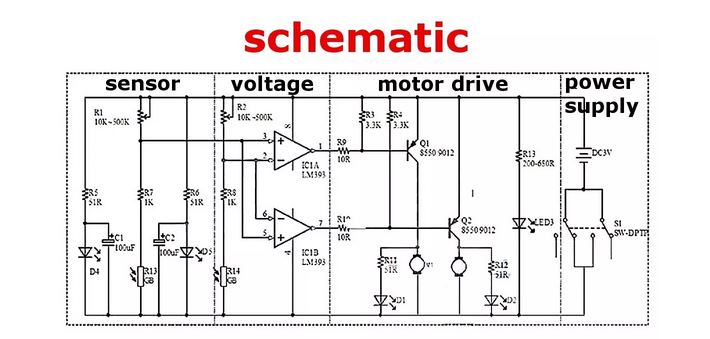
LM393 comparing two photosensitive resistance, when the imbalance (eg side pressure runway black) immediately control side of the motor stops rotating, the other side of the motor rotation acceleration, so that the car modification direction, return to the right direction, the whole process is a closed loop therefore rapid and sensitive control.
With the aim of simplifying the complex principle, we first have a by digital circuit to the intelligent tracking car, in the assembly process, we could not only familiar with the mechanical principle gradually can learn to: photocell, a voltage comparator, a motor drive circuit, and other related electronic knowledge.
Photosensitive resistance device:
This is light-sensitive resistance, it can detect the external light intensity, the stronger the outside light photosensitive resistance resistance is small, the outside light weaker resistance is greater when the red LED light projected on a white and black runway because reflection rate is different, the resistance value of the light-sensitive resistance will occur obvious difference for subsequent circuit control.
LM393 comparator integrated circuit:
LM393 is a dual voltage comparator integrated circuit, which consists of two independent precision voltage comparator. its role compare the two input voltage, based on the level of two input voltage change the level of output voltage. The output has two states: close to open or close to the low level, LM393 using open collector output, so it is necessary to add the pull resistance to output high level.
DC motor with gear reduction:
DC motor drive the car needs to slow down, otherwise to speed up the car, then ran too fast not control, and the deceleration torque is too small and could not run up. We specialize in custom of this type of motor is integrated with the reduction gear and greatly reducing the manufacture difficulty is very suitable for our use.
LM393 comparing two photosensitive resistance, when the imbalance (eg side pressure runway black) immediately control side of the motor stops rotating, the other side of the motor rotation acceleration, so that the car modification direction, return to the right direction, the whole process is a closed loop therefore rapid and sensitive control.
What's in the box?
1 x Electronic DIY Kit (batteries are not included)
Resources
Assembly steps:
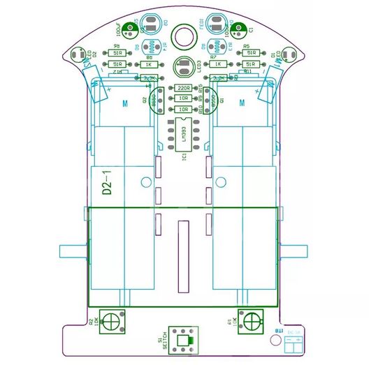
The first step: circuit part of the basic welding
The welding circuit part is relatively simple, the welding sequence according to the element height from low to high, the first 8 resistance welding, welding must use a multimeter to confirm whether the proper welding resistance, polar components such as transistors, green lights, definitely clear electrolytic capacitor polarity as reference element we are photo welding, welding capacitor short is the negative side of the insertion pin PCB screen printing shadow, green welding LED note long pin is positive, and the welding is not too long or easy bad welding, D4 D5 R13 R14 can temporarily do not weld, the integrated circuit chip can be inserted, preliminary after completion of welding check carefully prevent, be negligent.
Second step: mechanical assembly
The universal wheel screw is inserted into the PCB hole, and screwed into the universal wheel nut and a universal wheel. the battery box is stuck on the PCB by the double adhesive tape, the lead wire passes the PCB reserved Kong Han received PCB, the red line is connected with the 3 V positive power supply, and the yellow line is connected to the ground.
Mechanical part and assembly can be mounted first wheels, wheel consists of three pieces of black acrylic round tablets, assembly prior to exposing protective film, the inside of the wheel center hole grows circular hole, middle of the round plate diameter is relatively small, lateral wheel piece center hole Shiyuan, with two screw nuts fixed set good three round tablets, and black self-tapping screws fixed on the rotating shaft of the engine. Finally the silicone rubber tire sleeve on the wheel. Lead connection lead wire of the motor and the wheel assembly is the use of the glue on the PCB making position, attention wheels and the PCB edge retaining sufficient clearance, the motor leads are soldered to the PCB. Note that adequately longer lead, to avoid the motor rotation direction error is convenient for changing the lead wire of the order.
The third step: the installation of opto-electronic circuits
Photosensitive resistance and light-emitting diode (attention polarity) is the reverse installed on the PCB, and the ground distance of about 5mm, the distance between the light-sensitive resistance and light-emitting diode is also about 5mm. Finally can pass electrical test.
The fourth step: Vehicle debugging
In the battery box in 2 AA batteries, switches to dial in the "on", the car driving right reverse is traveling along the direction of the universal wheel, if hold the left side of the photosensitive resistance, the car to the right of the wheel rotation, Keep to the right of photosensitive resistance, the left side of the car wheel must turn, if car travel back can exchange connection of two motors at the same time. as one of the normal back on the other side as long as the exchange of the rear of the motor can be wiring.
Note: We don't supply any manuals, please note this before you buy this DIY kit.
- Availability: 136 In Stock
- Model: DIY track robot kit
-
Brand:
