
WaveShare


GNSS Positioning, As Well As Bluetooth Data Transfer
- Standard Raspberry Pi Pico header, supports Raspberry Pi Pico series boards
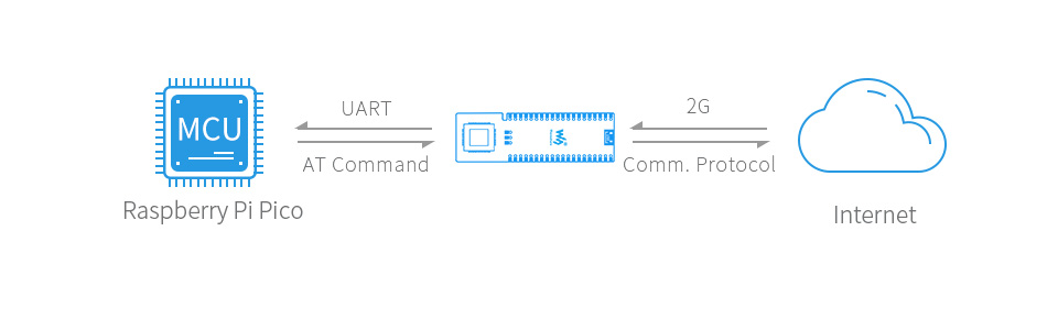
- UART communication, serial AT commands control
- Supports SMS, phone call, GPRS, DTMF, HTTP, FTP, MMS, email, etc.
- Bluetooth3.0 support, allows Bluetooth data transfer
- RTC real time clock, with rechargeable Li-po battery
- Integrates 3.7V Li-po battery connector and recharge circuit, allows being powered from external rechargeable Li-po battery, or recharging it in turn
- Onboard microphone, together with speaker header, can be used to make phone call
- 2x LED indicators, for monitoring the module operating status
- Onboard nano SIM card slot, supports 2G/4G SIM card *
- Comes with development resources and manual (Raspberry Pi Pico C/C++ and MicroPython examples)
| SIM868 | |||
|---|---|---|---|
| Applicable region | most countries/regions | ||
| FREQUENCY BAND | |||
| NB-IoT | N/A | B1/B2/B3/B4/B5/B8/B12/B13/B18/B19/ B20/B25/B26/B28/B66/B71/B85 | LTE-FDD: B1/B3/B5/B8/B20/B28 |
| Cat-M | N/A | B1/B2/B3/B4/B5/B8/B12/B13/B14/B18/ B19/B20/B25/B26/B27/B28/B66/B85 | N/A |
| 2G | GSM 850/EGSM 900/DCS 1800/PCS 1900 MHz | N/A | N/A |
| GNSS | GPS, GLONASS, BeiDou | GPS, GLONASS, BeiDou, Galileo | N/A |
| DATA RATE | |||
| NB-IoT(Kbps) | - | 136(DL)/150(UL) | 26.15(DL)/62.5(UL) |
| Cat-M(Kbps) | - | 589(DL)/1119(UL) | - |
| 2G(Kbps) | 85.6(DL)/85.6(UL) | - | - |
| OTHERS | |||
| Communication protocol | TCP/UDP/HTTP/SSL/FTP /POP3/SMTP/MQTT... | TCP/UDP/HTTP/HTTPS/TLS/DTLS /PING/LWM2M/COAP/MQTT... | |
| Power supply | External Li-po battery OR Raspberry Pi Pico USB port | ||
| Battery interface | 3.7V ~ 4.2V | ||
| Logic level | 3.3V | ||
| Module standalone current | Idle mode: 12mA | Idle mode: 10mA | Idle mode: 5.6mA |
| Sleep mode: 0.65mA | Sleep mode: 1.2mA | Sleep mode: 0.4mA | |
| Backup mode: 8uA | PSM mode: 3.2uA | PSM mode: 3.4uA | |
| Audio input/output | onboard microphone, with speaker header | N/A | |
| Indicator | NET: network indicator Charge: recharge indicator | ||
| Switch | Li-po battery and USB power supply switch | Li-po battery power supply switch | |
| SIM card | 2G SIM card (1.8V / 3V) | NB-IoT / Cat-M card (1.8V ONLY) | NB card (1.8V / 3V) |
| Antenna connector | LTE, GNSS, BT | LTE, GNSS | LTE |
| Dimensions | 76.15 × 24.00mm | 73.5 × 24.00mm | |
The Pico Can Be SMD-Mounted (Left), Or Attached Via Female Header (Right)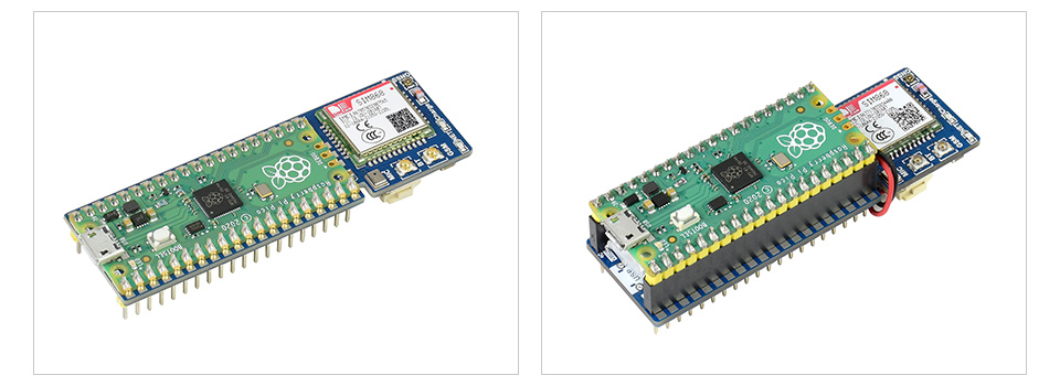
Connecting With Other Expansion Module And Antenna
Supports Communication Protocols Including: TCP/UDP/HTTP/SSL/FTP/POP3/SMTP/MQTT
GNSS Support Including GPS, GLONASS, BeiDou

Onboard Microphone, Together With Speaker Header, For Making Phone Call
Supports Sending SMS, MMS, And Email Via AT Commands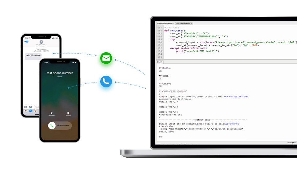
Allows Bluetooth Wireless Communication With Bluetooth3.0 Devices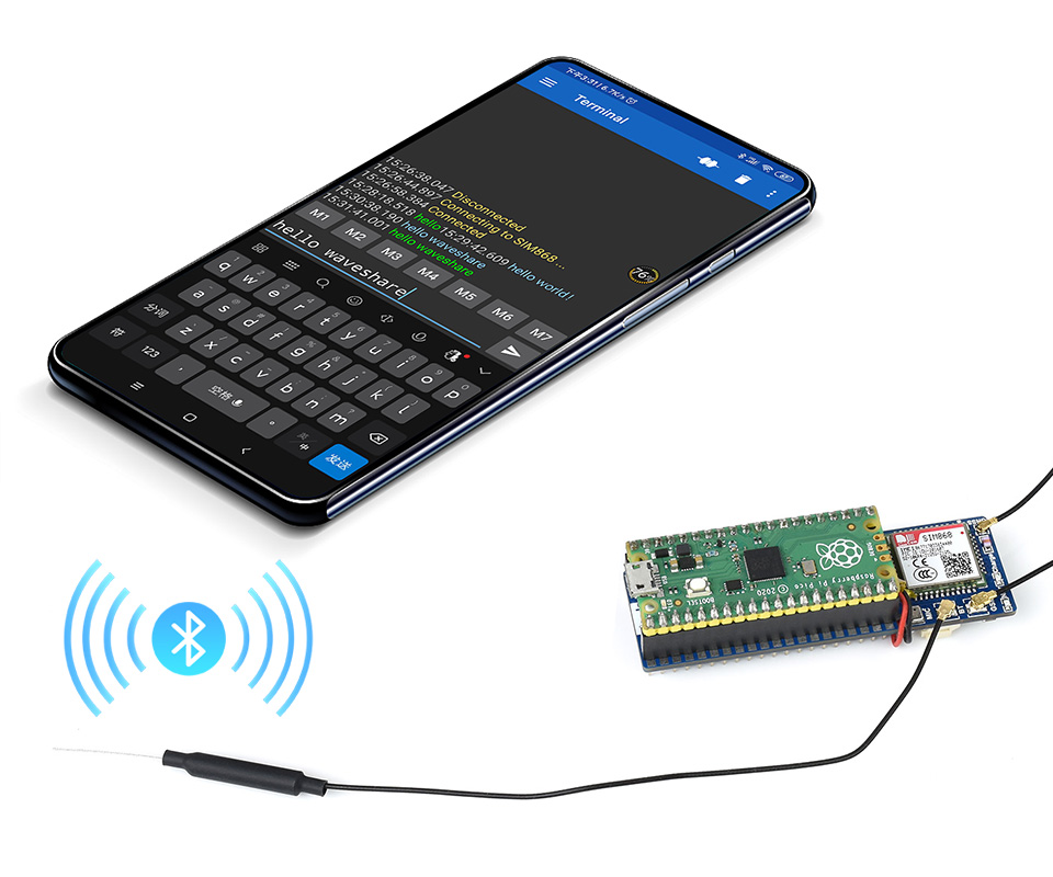
Pinout Definition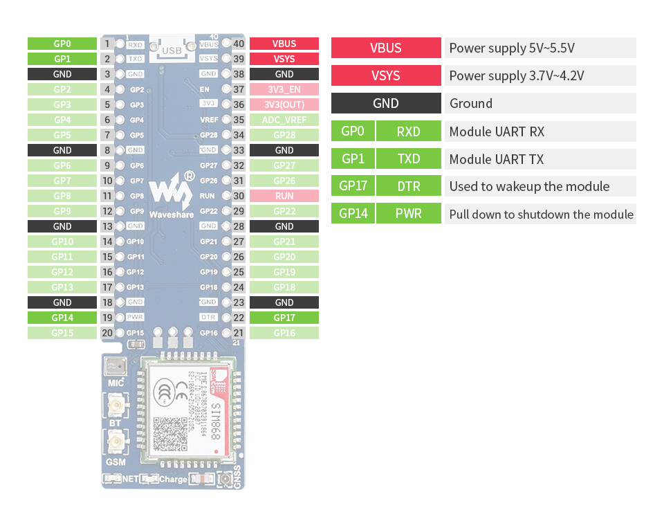
Outline Dimensions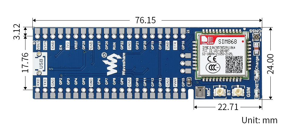
What's in the box?
1 x Pico-SIM868-GSM/GPRS/GNSS
1 x LTE antenna
1 x GPS antenna
1 x Bluetooth antenna
2 x 20PIN female pin header
1 x 40PIN male pin header
1 x 3.7V rechargeable Li-po battery
1 x Speaker
Resources
Wiki: Pico-SIM868-GSM/GPRS/GNSS

Raspberry Pi 5 provides two four-lane MIPI connectors, each of which can support either a camera or a display. These connectors use the same 22-way, 0.5mm-pitch “mini” FPC format and require adapter cables to connect to the 15-way, 1mm-pitch “standard” format connectors on current Raspberry Pi camera and display products.
Note that a camera cable should not be used with a display, and vice versa.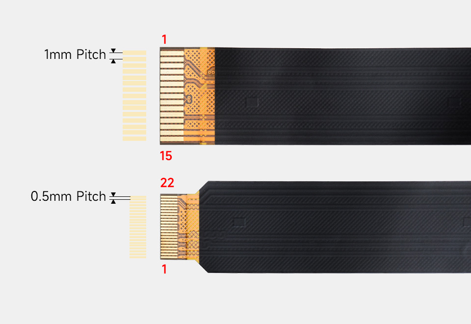
What's in the box?
1 x Raspberry Pi 5 Display Adapter Cable

| INPUT VOLTAGE | 5V DC (supplied via four-pin fan header on Raspberry Pi 5) |
|---|---|
| FAN SPEED CONTROL | Pulse width modulation control with tachometer |
| MAXIMUM AIRFLOW | 2.35 CFM |
| FAN SPEED | 8000±10%RPM |
| MATERIAL | Anodised aluminium |
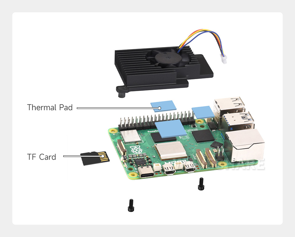
Matching The Size And Mounting Holes Of The Raspberry Pi 5, Combines An Aluminium Heatsink With An Active Cooling Fan To Accelerate Heat Dissipation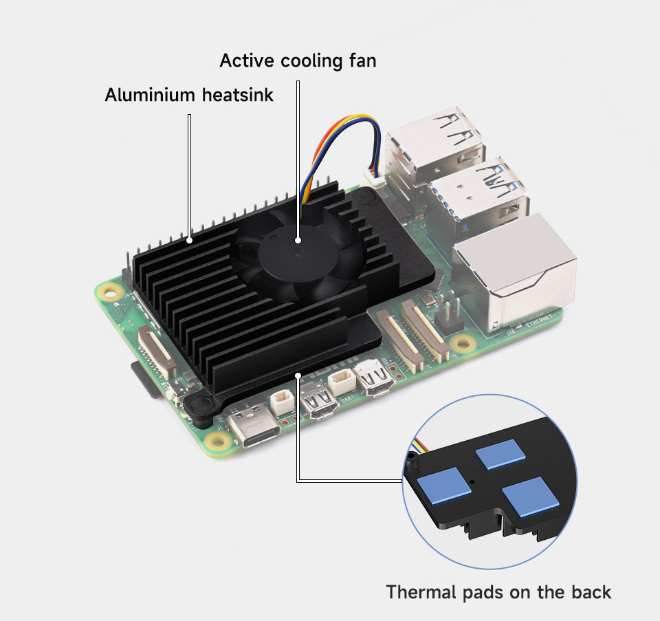
Connect The 4pin Cable To The Fan Header On Raspberry Pi 5, And Fix The Active Cooler Via M2.5 Nylon Screws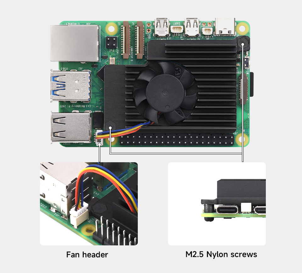
Raspberry Pi 5 Cooling Solution Comparing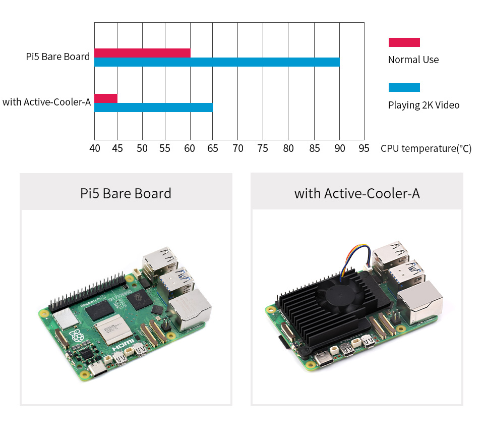
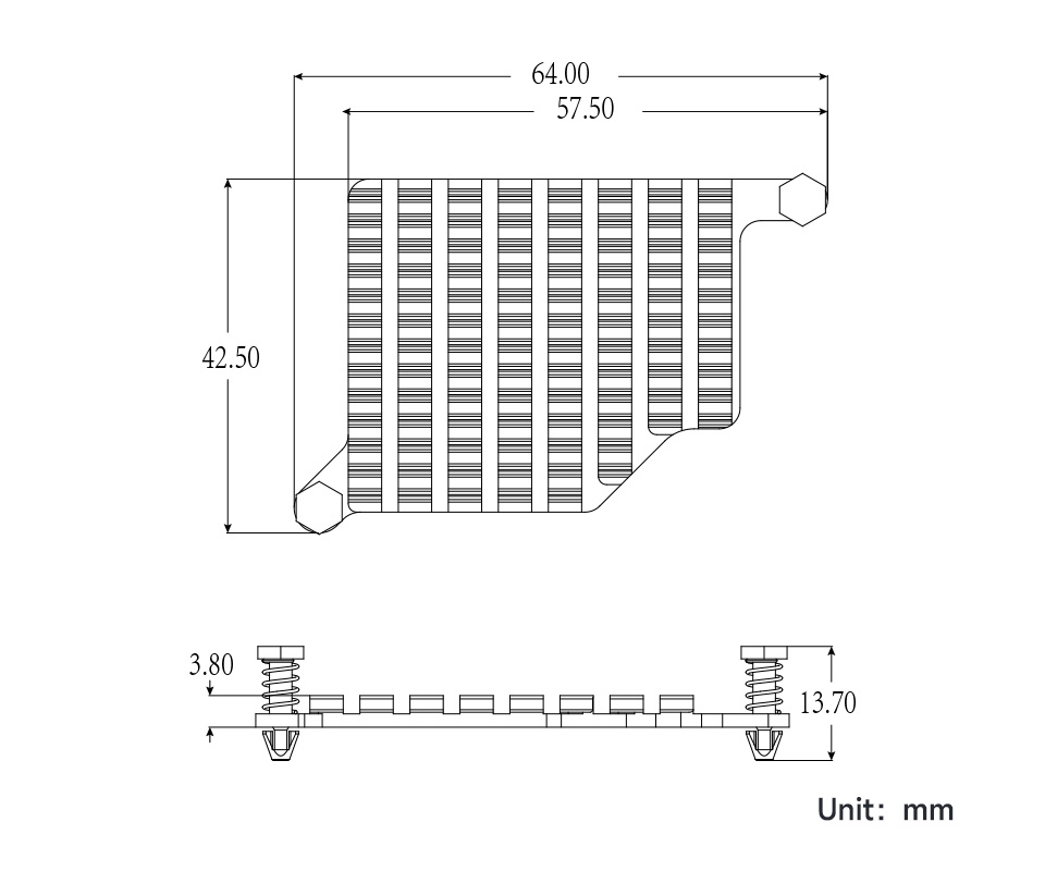
Outline Dimensions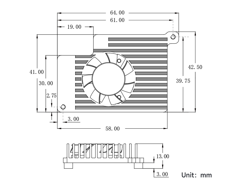
What's in the box?
1 x Active Cooler for Raspberry Pi 5 Aluminium Heatsink with Thermal Pads (Raspberry Pi 5 not included)
Raspberry Pi 5 provides two four-lane MIPI connectors, each of which can support either a camera or a display. These connectors use the same 22-way, 0.5mm-pitch “mini” FPC format and require adapter cables to connect to the 15-way, 1mm-pitch “standard” format connectors on current Raspberry Pi camera and display products.
Note that a camera cable should not be used with a display, and vice versa.
What's in the box?
1 x Raspberry Pi 5 Display Adapter Cable

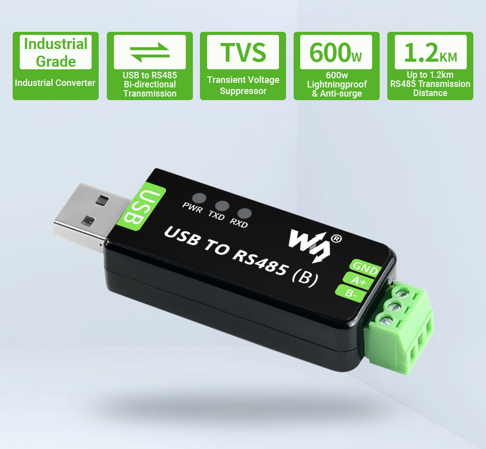
Features At A Glance
- Support USB to RS485 bidirectional conversion
- Fast communication, stable and reliable, better compatibility
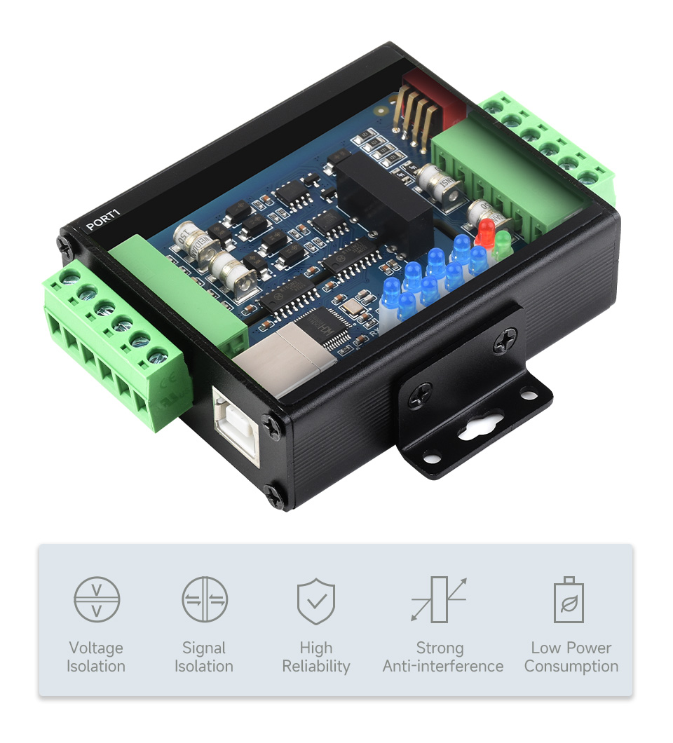
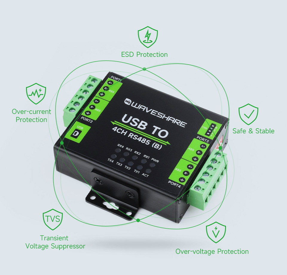
- Onboard TVS (Transient Voltage Suppressor), effectively suppress surge voltage and transient spike voltage in the circuit, lightning proof & anti-electrostatic
- Onboard resettable fuse and protection diodes, ensures the current/voltage stable outputs, provides over-current/over-voltage proof, improves shock proof performance
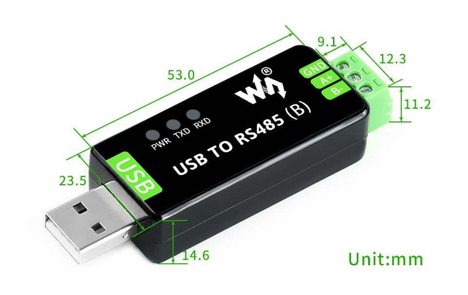
- 3 LEDs for indicating the power and transceiver status
Specifications
| PRODUCT TYPE | Industrial Grade USB to RS485 converter | |
|---|---|---|
| HOST PORT | USB | |
| DEVICE PORT | RS485 | |
| BAUDRATE | 300bps ~ 3Mbps | |
| USB | Operating voltage | 5V |
| Connector | USB-A | |
| Protection | 200mA self-recovery fuse, ESD protection | |
| Transmission distance | About 5m | |
| RS485 | Connector | Screw terminal |
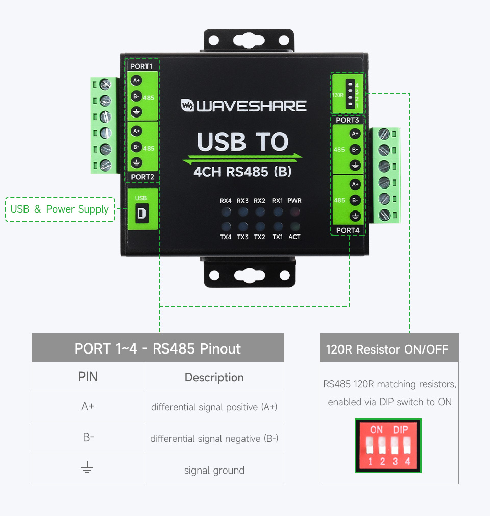
| Pins | A+, B-, GND | |
| Direction control | Hardware automatic control | |
| Protection | 600W lightningproof and surge-suppress, 15KV ESD protection (onboard 120R balancing resistor) | |
| Transmission distance | About 1.2km(low rate) | |
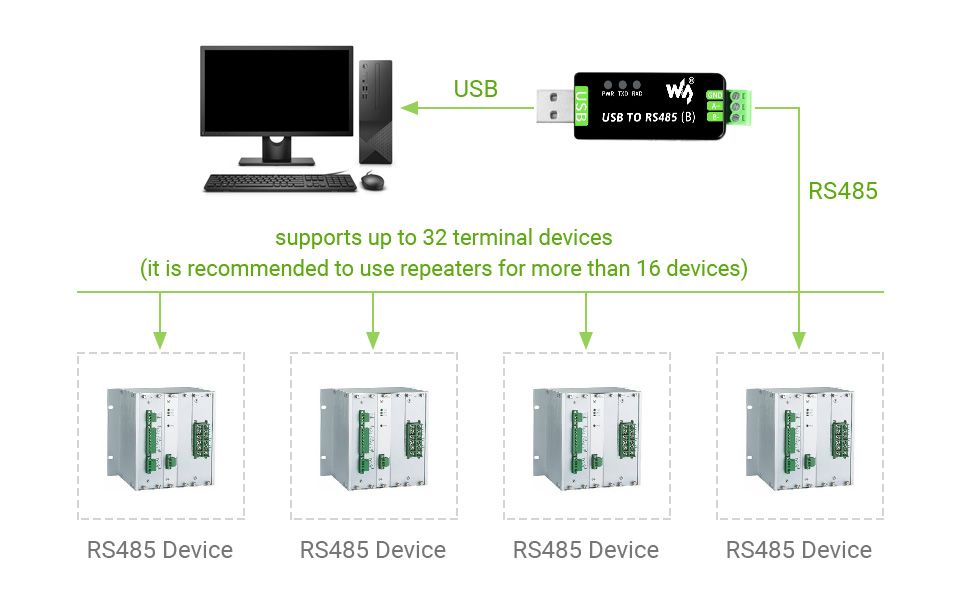
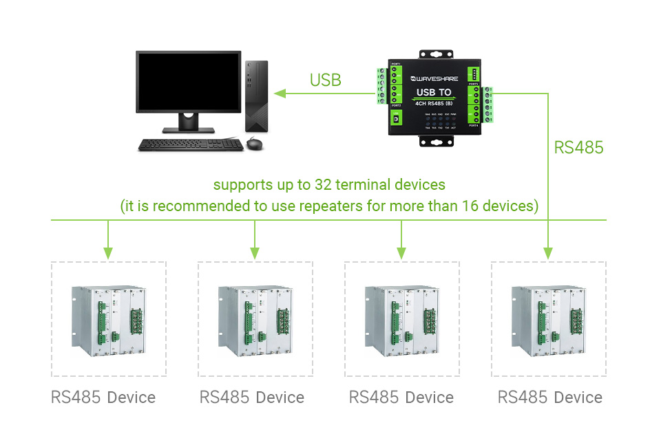
| Transmission mode | Point-to-multipoints (up to 32 nodes, it is recommended to use repeaters for 16 nodes or more) | |
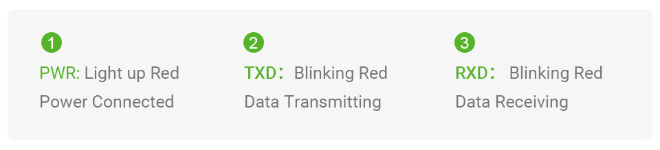
| LED INDICATORS | PWR | Red power indicator, light up when there is USB connection and voltage is detected |
| TXD | Red TX indicator, light up when the USB port sends data | |
| RXD | Red RX indicator, light up when the device ports send data back | |
| OPERATING ENVIRONMENT | Temperature | -15℃ ~ 70℃ |
| Humidity | 5%RH ~ 95%RH | |
| OPERATING SYSTEM | Mac, Linux, Android, WinCE, Windows 11 / 10 / 8.1 / 8 / 7 | |
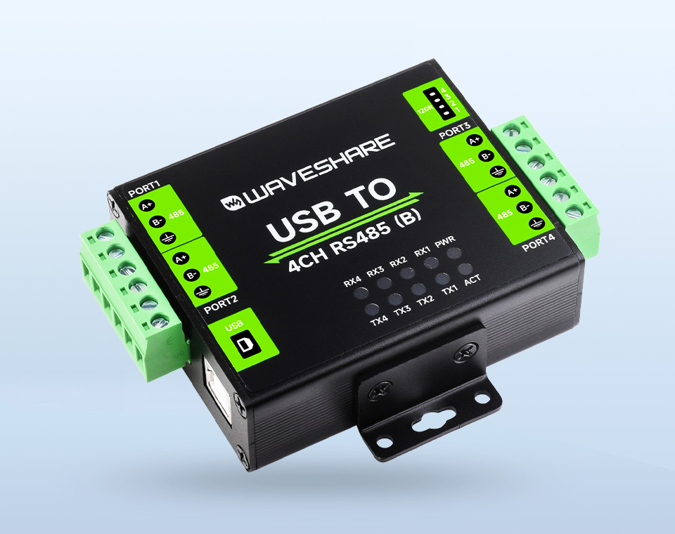
Onboard Original CH343G And SP485EEN Chips, Providing Better Stability And Compatibility, Built-In Lightningproof Tube, Resettable Fuse, ESD And TVS Protection Circuits, Etc.
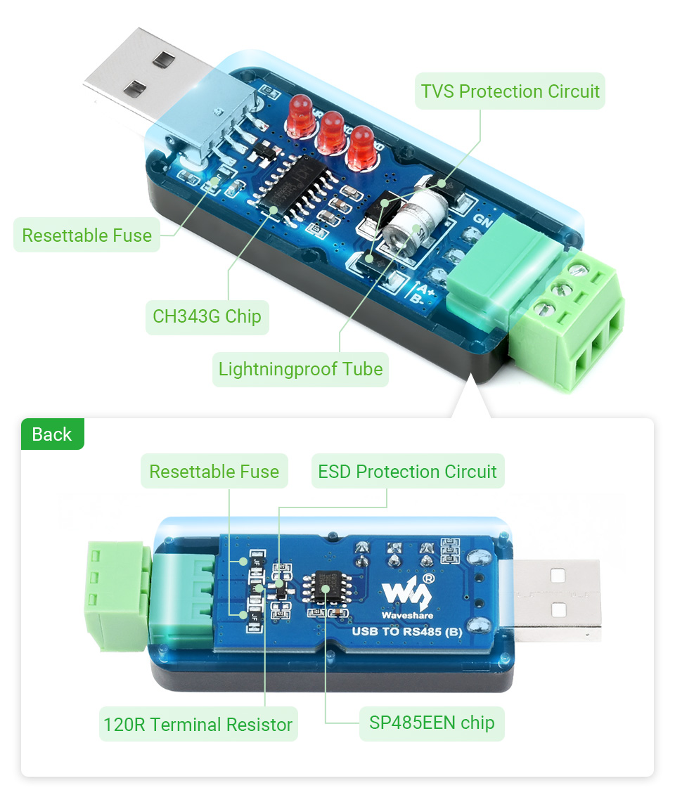
The USB Signal Can Be Converted Into A Balanced Differential RS485 Signal And The Transmission Rate Is Stable. The Reliable Speed Is 300bps ~ 3Mbps, The Transmission Distance Is About 1.2km For RS485, And About 5 Meters For USB.
Supports Mac, Linux, Android, WinCE, Win11/10/8.1/8/7/XP, Etc.
Onboard 3 LEDs For Indicating The Power And Transceiver Status
What's in the box?
1 x USB TO RS485 Bidirectional Converter
Resources
www.waveshare.com/wiki/USB_TO_RS485_(B)

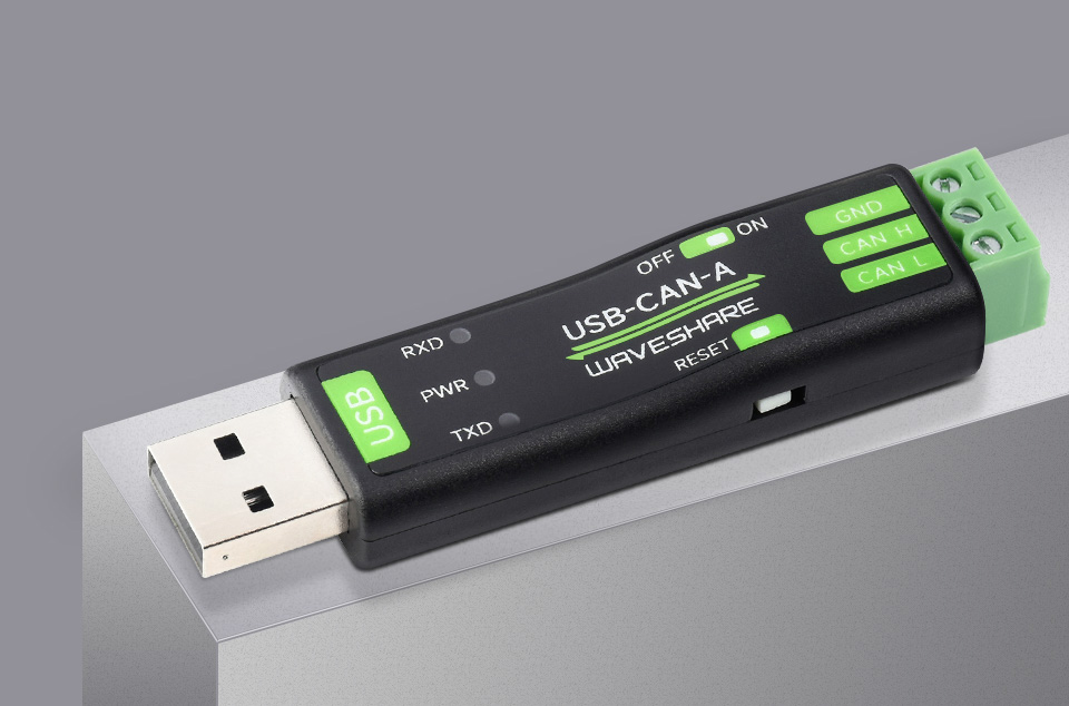
STM32 Chip Solution, Multi-System Compatible, Multiple Working Modes
Features At A Glance
- Supports CAN2.0A (standard frame) and CAN2.0B (extended frame)
- CAN baud rate is configurable in the range of 5Kbps-1Mbps
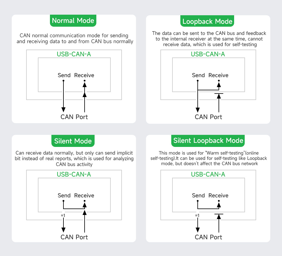
- Supports 4 working modes: normal mode, loopback mode, silent mode, silent loopback mode
- Supports multiple CAN data sending modes: single frame, multiple frames, manually, regularly and cyclic sending
- Supports multiple CAN data receiving modes: can be configured to only receive data from a certain ID, or specify ID to automatically answer the configured data
- Data can be saved as TXT or Excel
- Supports CAN bus detection for status checking
- Sending/receiving CAN data with time scale, allows sequentially displaying
- Baud rate of USB virtual COM port is configurable in the range of 9600 ~ 2000000bps (2000000bps by default)
- Supports setting working parameters by configuration software or serial command, can be saved after power off
- Adopts STM32 chip solution, stable and reliable communication
- Onboard TVS (Transient Voltage Suppressor), effectively suppress surge voltage and transient spike voltage in the circuit
- Comes with master computer software for Windows system, easy to use
- Easy secondary development, just need to modify the sending and receiving commands
Collects Data From CAN Bus To PC Via USB For Transceiver Control, Data Analysis,
Acquisition And Monitoring Of CAN Bus Network
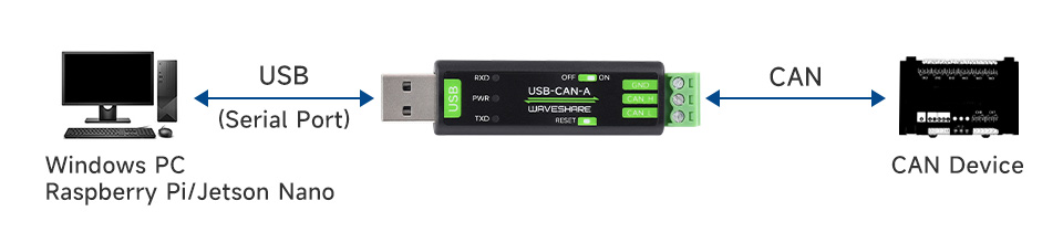
CAN Baud Rate Is Configurable In The Range Of 5Kbps-1Mbps

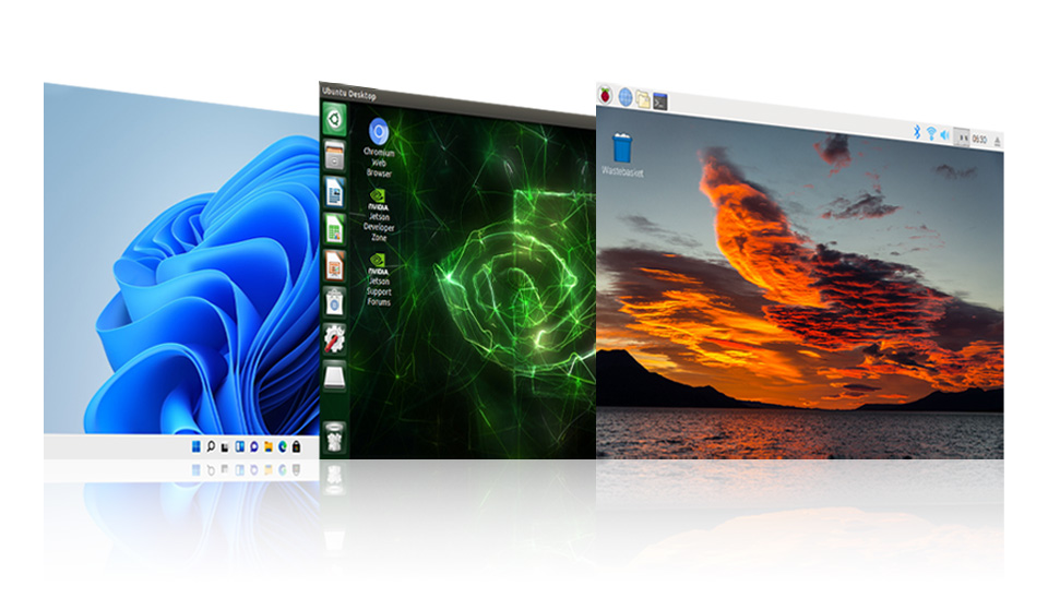
Support Windows XP/7/8/10/11 And Linux Systems Such As Raspberry Pi OS And Ubuntu Under Jetson Nano, Support Secondary Development
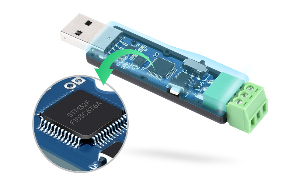
Adopts STM32 Chip Solution
Adopts The Original STM32F103 Chip, Stable And Reliable Communication
What's in the box?
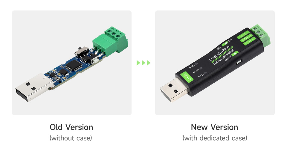
1 x USB-CAN-A
1 x USB Cable ~1.5m
1 x Screwdriver
Resources

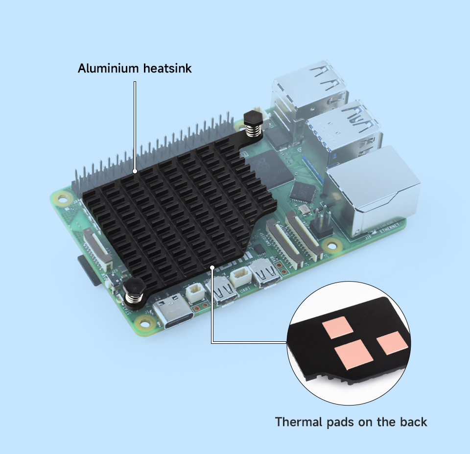
Dedicated Aluminum Heatsink, Corrosion / Oxidation Resisting, Better Heat Dissipation
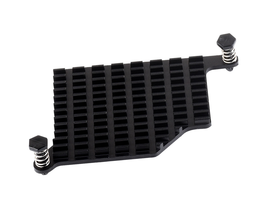
Matches The Size And Mounting Holes Of The Raspberry Pi 5, With Thermal Pads
1 x Pi5-Active-Cooler-C
1 x Thermal pad (3PCS)
How To Install
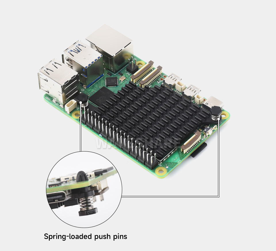
Attach The Thermal Pads And Fix The Aluminum Heatsink Via Spring-Loaded Push Pins
* for reference only, the Raspberry Pi 5 and TF card are NOT included.

Adopts Temperature-Controlled Blower Fan, Faster Heat Dissipation, More Durable
* for reference only, the Raspberry Pi 5 is NOT included
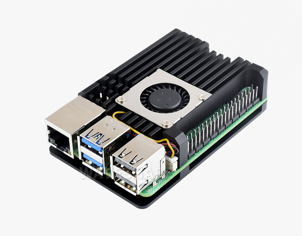
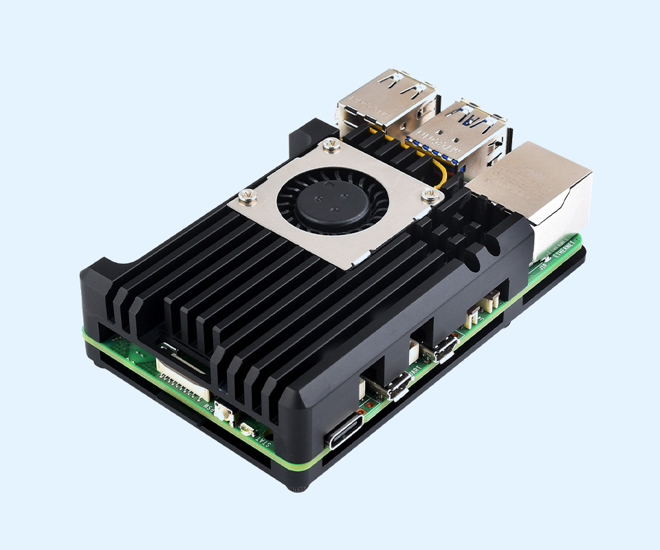
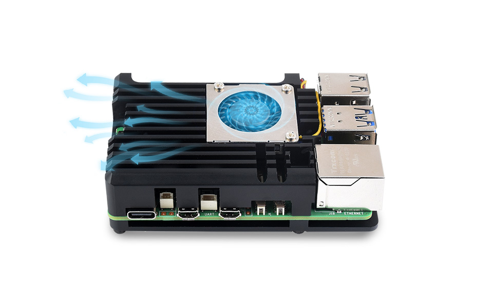
Aluminium Alloy Case, With Temperature-Controlled Blower Fan And Aluminium Heatsink
For Better Heat Dissipation
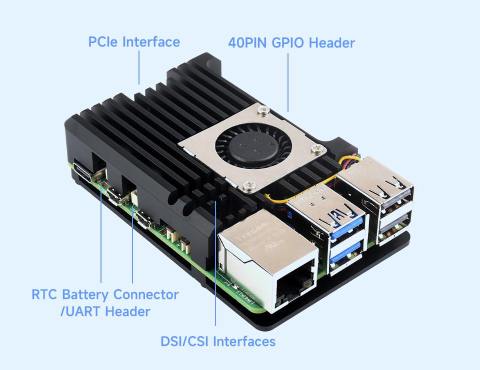
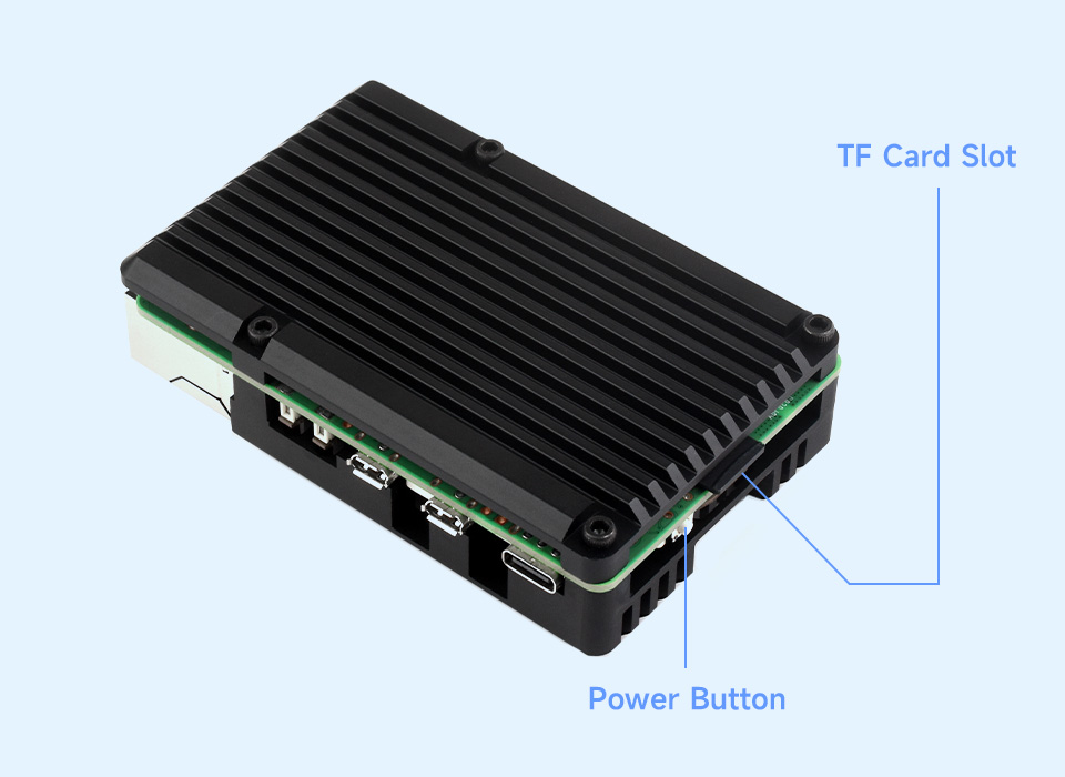
More Details
Adopts Advanced Metal Cutting Processing, With Precise Openings For Sorts Of Connectors, More Convenient For Wiring
The Fins Work Together With The Cooling Fan To Accelerate Heat Dissipation, Ensuring Stable Operation Of The Raspberry Pi 5
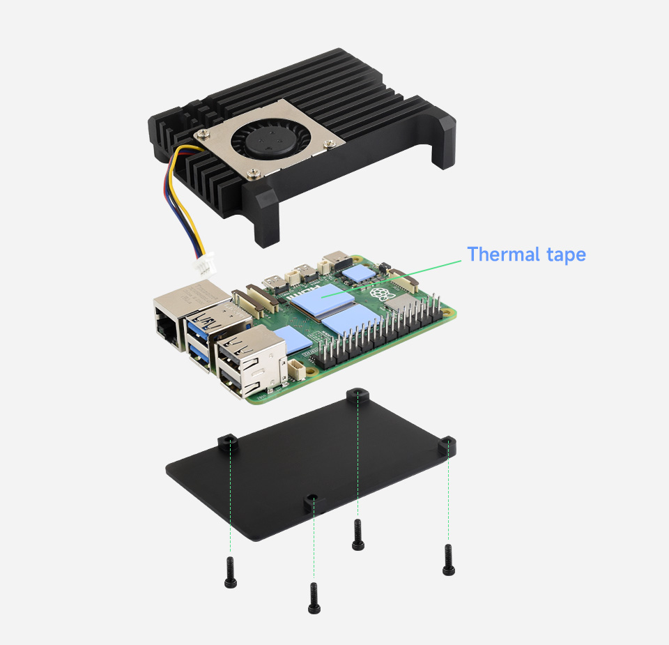
What's in the box?
1 x Aluminium Alloy lower plate
1 x Aluminium Alloy upper plate
1 x Cooling fan
1 x Screwdriver
1 x L-form hex socket spanner
1 x Thermal tape 4PCS
1 x Screws pack
The Case Consists Of Upper And Lower Cover Plates, With Thermal Tapes,
Easy To Install

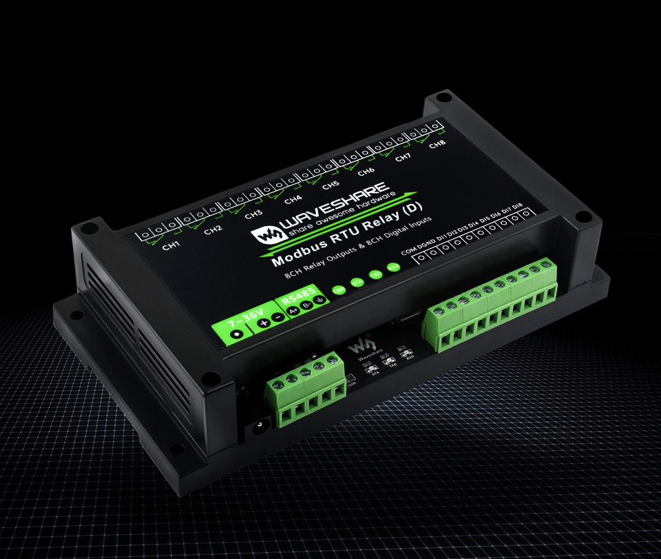
Modbus RTU Protocol, Multi Isolation Protection Circuits, Safe & Stable & Reliable
Features At A Glance
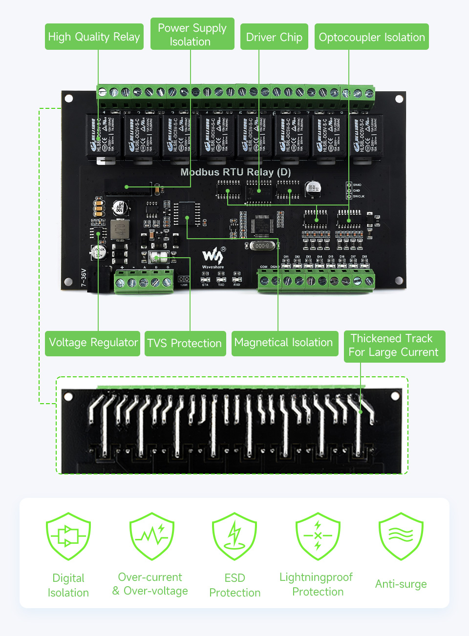
This is an industrial 8-ch relay module controlled via RS485 bus, with 8-ch digital input, utilizing Modbus RTU protocol. It features embedded protection circuits such as power isolation, magnetical isolation, and TVS diode, etc. It also comes with an ABS enclosure. The Modbus RTU Relay (D) is very easy to use. Due to its fast communication, stability, reliability, and safety, it is an ideal choice for industrial control equipments and/or applications with high communication requirement.
- Configurable device address (1~255), multi devices can be cascaded on RS485 bus
- Features flash-on, flash-off function, by passing argument to the command, it is possible to turn on the relay for a while and then close it automatically
- Onboard unibody power supply isolation, provides stable isolated voltage, needs no extra power supply for the isolated terminal
- Onboard unibody magnetical isolation, allows signal isolation, high reliability, strong anti-interference, low power consumption
- Onboard resettable fuse and TVS (Transient Voltage Suppressor), effectively suppress surge voltage and transient spike voltage in the circuit, provides over-current/over-voltage proof, lightningproof & anti-electrostatic
- Onboard Optocoupler isolation, prevent the relay from being interfered by high-voltage circuit
- Adopts dedicated relay driver chip, with built-in flyback diode protection, for stronger and more stable driving ability
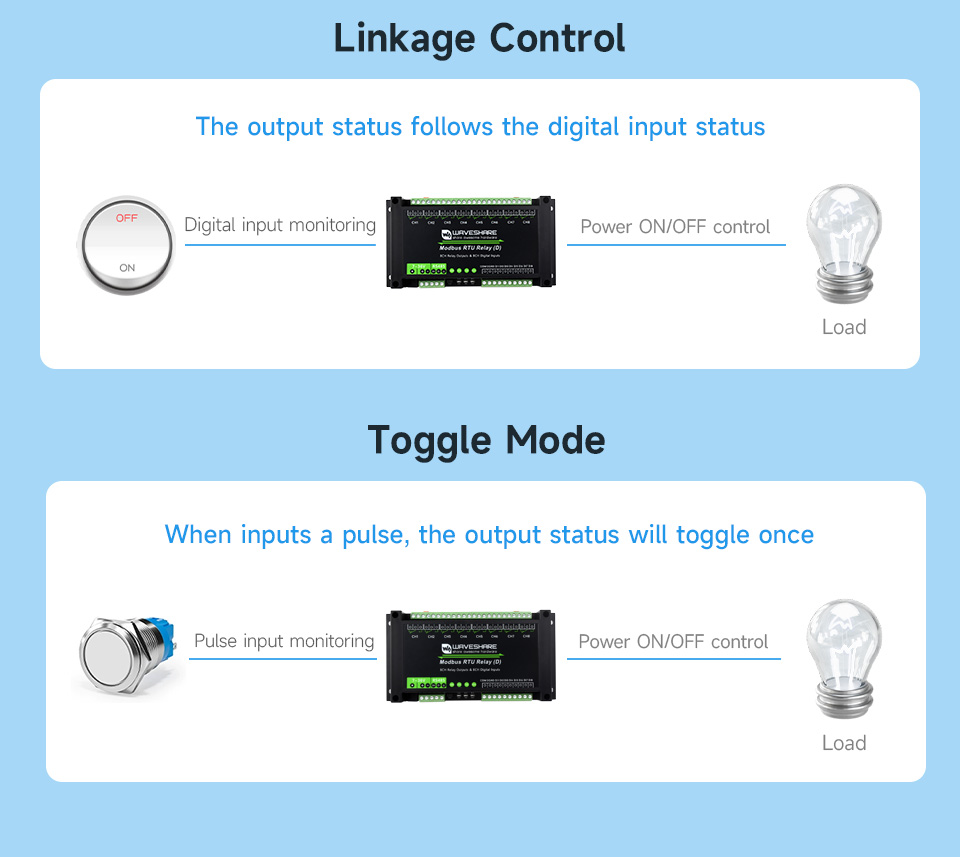
- Supports passive and active digital input, with bi-directional optocoupler isolation, built in debouncing algorithm. The relay supports digital input linkage control or toggle control
- Reverse-proof circuit, prevent the circuit from being damaged accidentally by incorrect connection
- High quality relay, contact rating: ≤10A 250VAC/30VDC
- Rail-mounted ABS plastic enclosure, easy to install, safe to use
- Multiple LEDs for indicating the MCU status and signal transceiving status
| POWER SUPPLY | 7~36V |
|---|---|
| COMMUNICATION INTERFACE | RS485 |
| BAUDRATE | 4800, 9600, 19200, 38400, 57600, 115200, 128000, 256000 |
| DEFAULT COMMUNICATION FORMAT | 9600, N, 8, 1 |
| RELAY CHANNELS | 8 |
| CONTACT FORM | 1NO 1NC |
| CONTACT RATING | ≤10A 250VAC/30VDC |
| DIGITAL INPUT | 8DI, 5~36V, passive / active input (NPN or PNP), built-in bi-directional optocoupler isolation |
| COMMUNICATION PROTOCOL | Standard Modbus RTU protocol |
| RS485 ADDRESS | 1~255 |
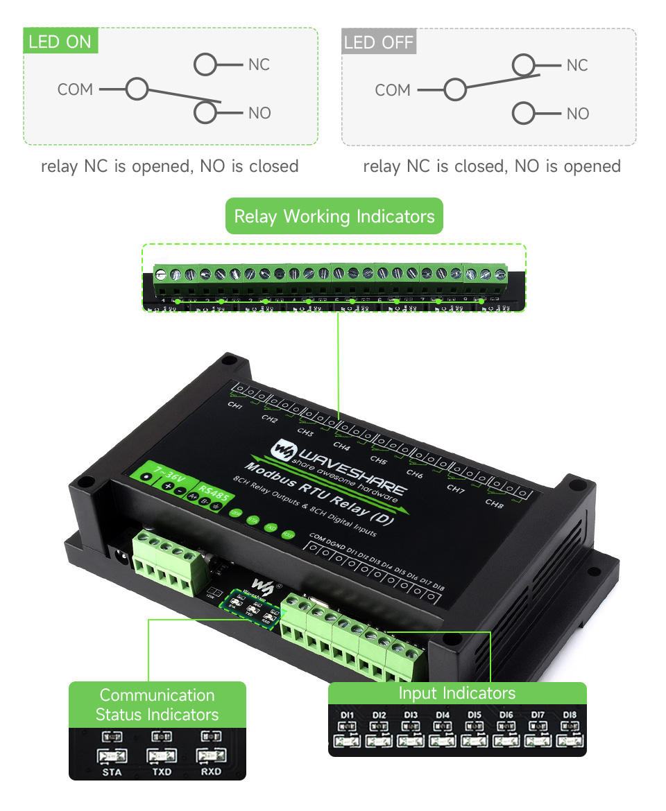
| LED INDICATORS | STA: MCU indicator, keeps flashing when the MCU normally working TXD: TX indicator, lights up when sending data RXD: RX indicator, lights up when receiving data |
Primary Function
Supports Reading Digital Input By Sending Modbus RTU Protocol Commands Via RS485 For Relay Output Control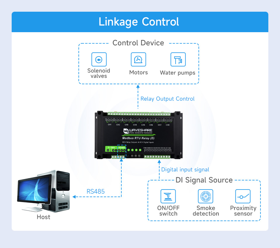
Hardware Analysis
Multiple Protections For Safer And More Reliable Use
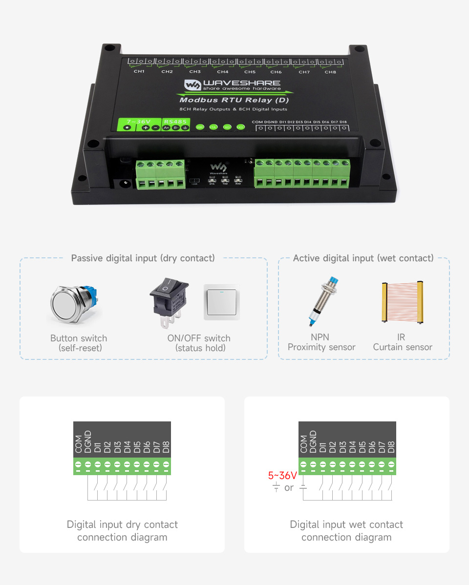
Digital Input
Supports Passive (Dry Contact) And Active (Wet Contact) Digital Input, With Bi-Directional Optocoupler Isolation
Interfaces & Indicators
With Multiple LED Indicators, Easy To Monitor The Operating Status
Supports Multiple Relay Control Modes, Each Channel Supports Independent
Control Mode Setting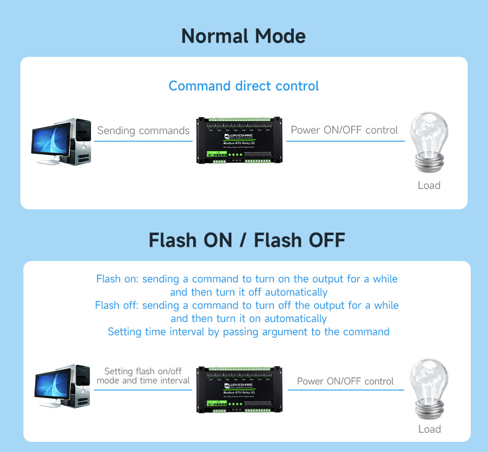
RS485 Communication
Configurable Device Address (1~255), Multi Devices Can Be Cascaded On RS485 Bus
In Case Of Many Devices Are Cascaded, Or Communication Distance Is Quite Long, It Is Necessary To Use RS485 Repeaters
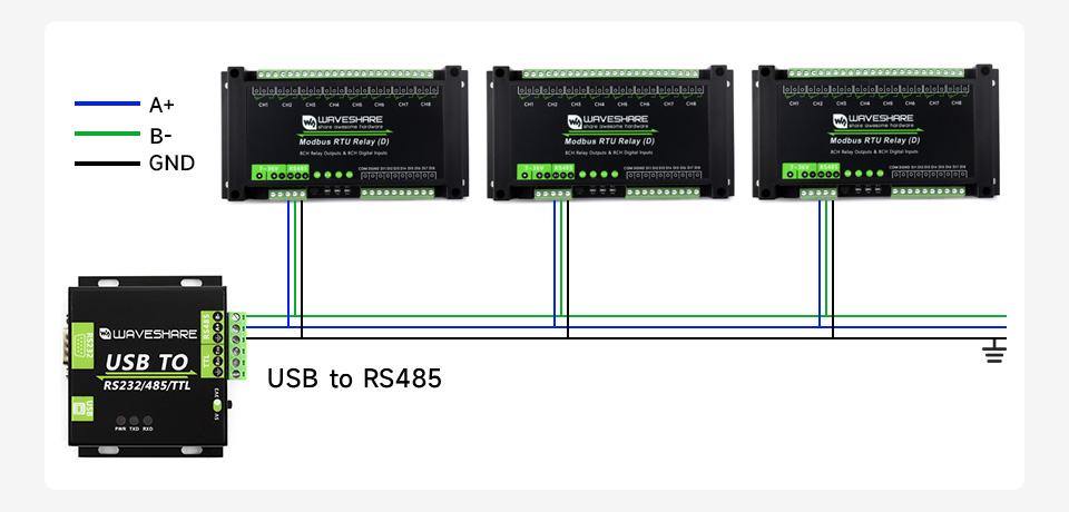
for reference only, the USB TO RS232/485/TTL converter is Not included
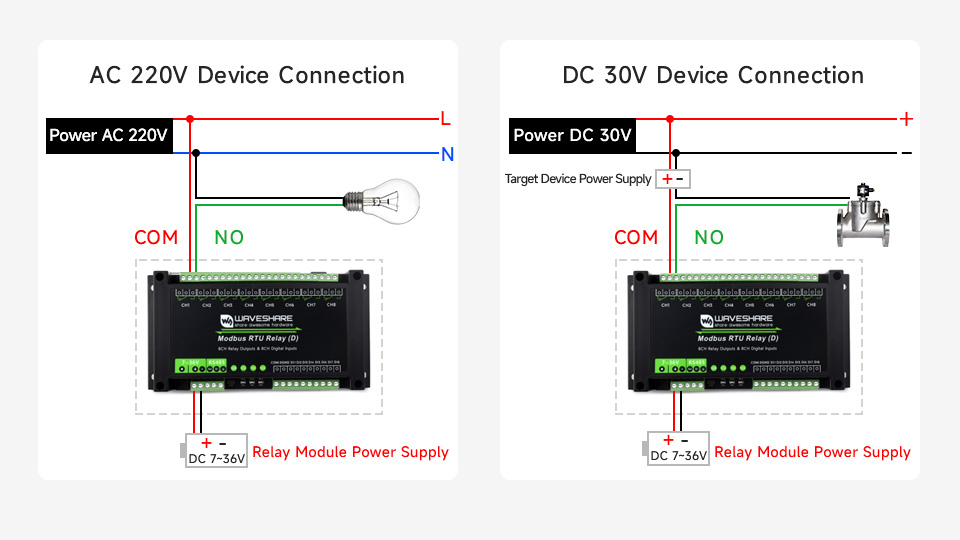
Relay Connection
Contact Rating Of The Onboard Relay Up To 10A 250VAC/30VDC
Directly Controlling 220VAC Home Appliances, Or Devices Below 30VDC
Enclosure Design
Rail-Mounted ABS Plastic Enclosure, Easy To Install, Safe To Use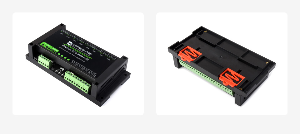
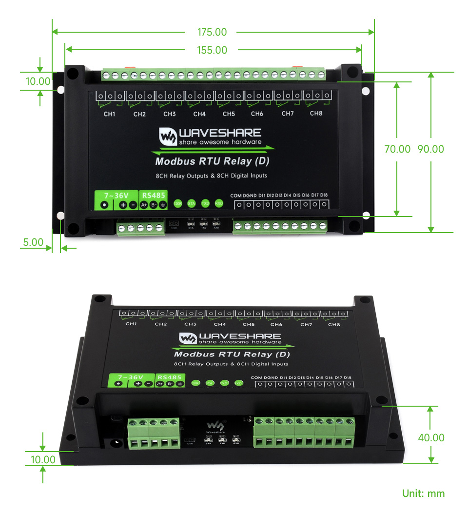
Outline Dimensions
What's in the box?
1 x Modbus RTU Relay (D)
1 x Screwdriver
Resources
WIKI: www.waveshare.com/wiki/Modbus_RTU_Relay_(D)

CH344L | Stable Transmission | Multiple Devices Applicable | Multi-OS Compatible
Features At A Glance
- Adopts original CH344L chip, fast communicating, stable and reliable, better compatibility
- Supports USB to 4-ch isolated RS485, convenient for expanding multiple RS485 industrial serial devices
- Onboard unibody power supply isolation, provides stable isolated voltage, needs no extra power supply for the isolated terminal
- Onboard unibody digital isolation, allows signal isolation, high reliability, strong anti-interference, low power consumption
- Onboard TVS (Transient Voltage Suppressor), effectively suppress surge voltage and transient spike voltage in the circuit, lightningproof & ESD protection
- Onboard self-recovery fuse and protection diodes, ensures the current/voltage stable outputs, provides over-current/over-voltage proof, improves shock proof performance
- Onboard RS485 output terminal 120R resistors, enabled/disabled via DIP switch
- 10 LEDs for indicating the power, device configuration status and transceiver status
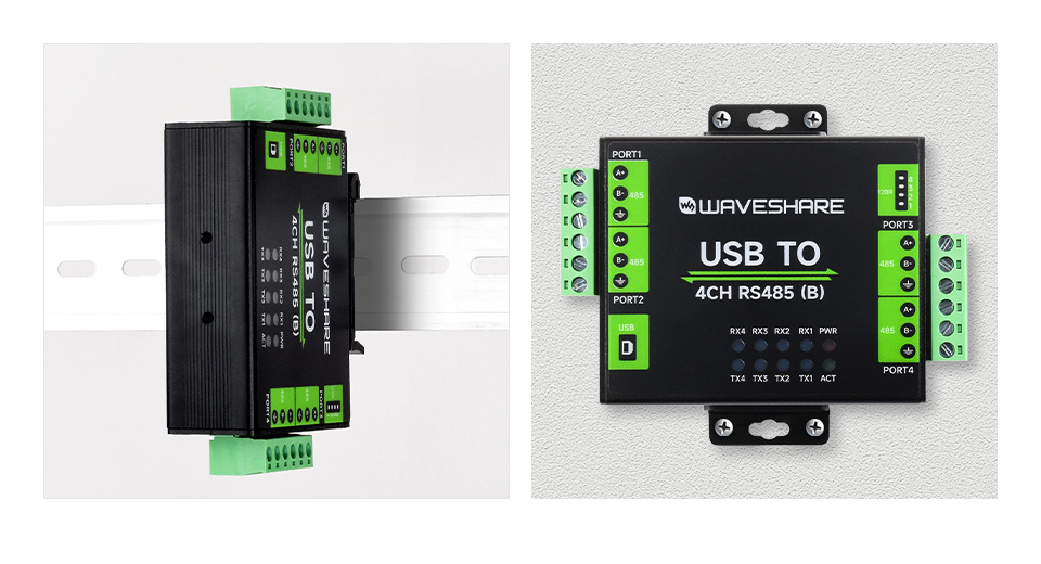
- Industrial grade metal case, supports wall-mount & rail-mount installation, solid and beautiful, easy to install
Specifications
| PRODUCT TYPE | Industrial isolated USB to RS485 converter | |
|---|---|---|
| HOST PORT | USB | |
| DEVICE PORT | RS485 | |
| BAUDRATE | 1200bps ~ 460800bps | |
| USB | Operating voltage | 5V |
| Connector | USB-B | |
| Protection | 500mA resettable fuse, output isolation | |
| ISOLATED RS485 | Connector | Screw terminal |
| Direction control | Hardware automatic control | |
| Protection | 600W lightningproof and surge-suppress, 15KV ESD protection (onboard 120R matching resistors) | |
| Transmission mode | Point-to-multipoints (up to 32 nodes, it is recommended to use repeaters for 16 nodes or more) | |
| INDICATORS | PWR | Power indicator, lights up while the USB is connected and voltage is detected |
| ACT | Status indicator, lights up green while the driver is detected. | |
| RXD | RXD indicator, lights up when the device ports send data back | |
| TXD | TXD indicator, lights up when the USB port is sending data | |
| OPERATING ENVIRONMENT | Temperature | -40 ~ 85℃ |
| Humidity | 5%RH ~ 95%RH | |
| OPERATING SYSTEM | Win7/8/8.1/10/11, Mac, Linux, Android | |
Safer Isolated Design
- Onboard unibody power supply isolation, provides stable isolated voltage, needs no extra power supply for the isolated terminal
- Onboard unibody digital isolation, allows signal isolation, high reliability, strong anti-interference, low power consumption
Multiple Protection, Safe And Stable
Onboard TVS (Transient Voltage Suppressor), effectively suppress surge voltage and transient spike voltage in the circuit, lightningproof & ESD protection. Onboard self-recovery fuse and protection diodes, ensures the current/voltage stable outputs, provides over-current/over-voltage proof, improves shock proof performance.
Multi System Support
Supports Mac, Linux, Android, Windows 11 / 10 / 8.1 / 8 / 7, Etc.
Transmission Distance Up To 1.2km
The USB Signal Can Be Converted Into 4 Balanced Differential RS485 Signals And The Transmission Rate Is Stable. The Reliable Speed Is 1200~460800bps, The Transmission Distance Is About 1.2km For RS485, And About 5 Meters For USB
Aluminium Alloy Enclosure
Aluminium Alloy Enclosure With Sand Blasting And Anodic Oxidation,
Solid And Durable, Fashionable And Good Hand Feeling
Wall-Mount & Rail-Mount Support, More Flexible For Industrial Installation
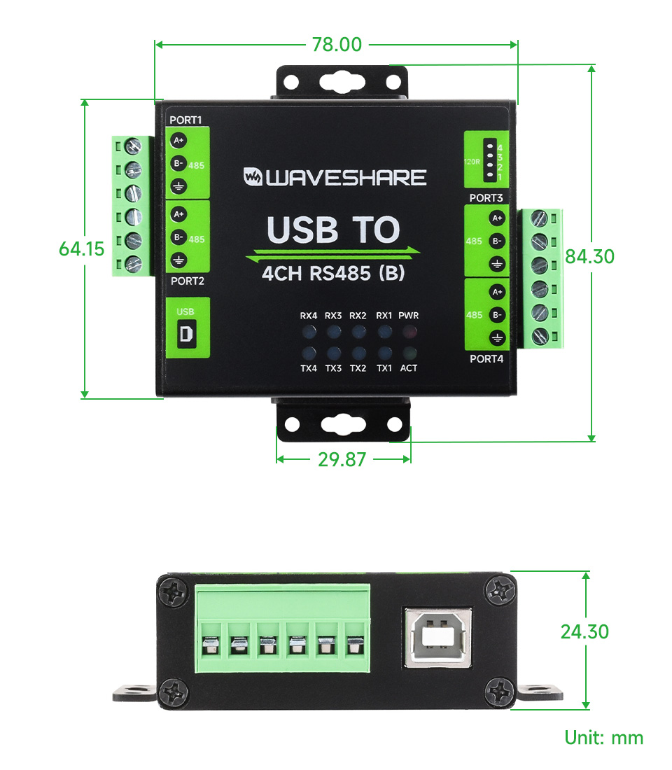
Outline Dimensions
What's in the box?
1 x USB TO 4CH RS485 (B)
1 x Rail-mount buckle
1 x USB type A to type B cable ~1.2m
1 x Screwdriver
Resources
www.waveshare.com/wiki/USB_TO_4CH_RS485_(B)

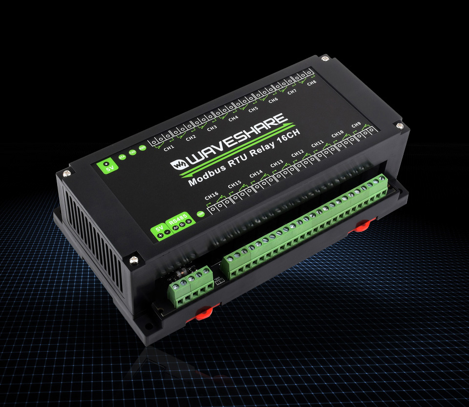
Modbus RTU Protocol, Multi Isolation Protection Circuits, Safe & Stable & Reliable
Features At A Glance
This product is an industrial 16-ch relay module controlled via RS485 bus, adopts Modbus RTU protocol, built-in protection circuits such as power supply isolation, magnetical isolation, resettable fuse, and TVS diode, etc. It also comes with an ABS case.
The Modbus RTU 16-Ch Relay is very easy to use. Due to its fast communication, stability, reliability, and safety, it is an ideal choice for industrial control equipments and/or applications with high communication requirements.
- Configurable device address (1~255), multi devices can be cascaded on RS485 bus
- Features flash-on, flash-off function, by passing argument to the command, it is possible to turn on the relay for a while and then close it automatically
- Onboard unibody power supply isolation, provides stable isolated voltage, needs no extra power supply for the isolated terminal
- Onboard unibody magnetical isolation, allows signal isolation, high reliability, strong anti-interference, low power consumption
- Onboard resettable fuse and TVS (Transient Voltage Suppressor), effectively suppress surge voltage and transient spike voltage in the circuit, provides over-current/over-voltage proof, lightningproof & anti-electrostatic
- Onboard Optocoupler isolation, prevent the relay from being interfered by high-voltage circuit
- Onboard dedicated relay driver chip, with built-in freewheeling diode protection, the driving ability is stronger and more stable
- Reverse-proof circuit, prevent the circuit from being damaged accidentally by incorrect connection
- High quality relay, contact rating: ≤10A 250VAC/30VDC
- Rail-mounted ABS case, easy to install, safe to use
- 3 LEDs for indicating the MCU status and signal transceiving status
Specifications
| OPERATING VOLTAGE | 5V |
|---|---|
| COMMUNICATION INTERFACE | RS485 |
| BAUDRATE | 4800, 9600, 19200, 38400, 57600, 115200, 128000, 256000 |
| DEFAULT COMMUNICATION FORMAT | 9600, N, 8, 1 |
| RELAY CHANNELS | 16 |
| CONTACT FORM | 1NO 1NC |
| COMMUNICATION PROTOCOL | Standard Modbus RTU protocol |
| RS485 ADDRESS | 1~255 |
| LED INDICATORS | STA: MCU indicator, keep flashing when the MCU normally working TXD: TX indicator, lights up when sending data RXD: RX indicator, lights up when receiving data |
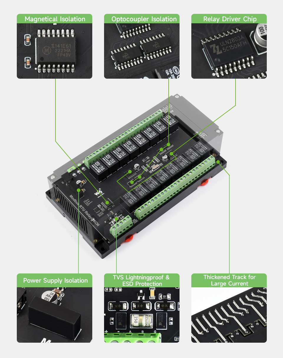
Onboard Multiple Isolation Protection Circuit
Multiple Protections, More Safe And Reliable
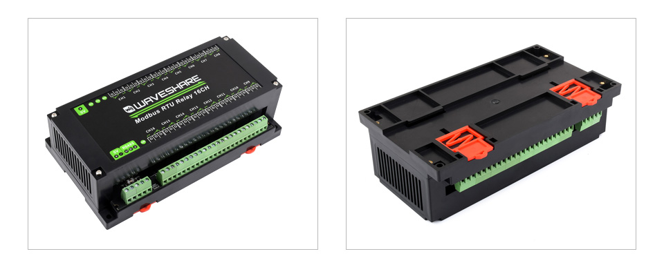
Rail-Mount Case Design
Rail-Mounted ABS Protective Enclosure, Easy To Install, Safe To Use
RS485 Communication
Configurable Device Address (1~255), Multi Devices Can Be Cascaded On RS485 Bus
In Case Of Many Devices Are Cascaded, Or The Communication Distance Is Quite Long, It Is Necessary To Use RS485 Repeaters
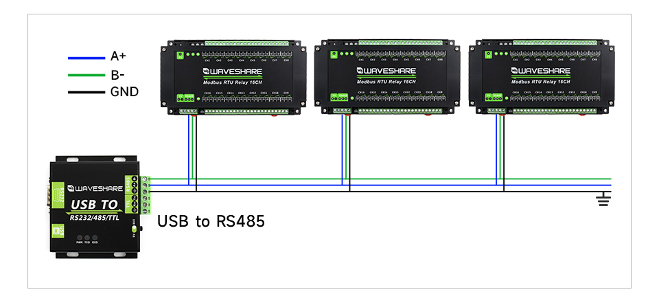
* for reference only, the USB to RS485 is NOT included.
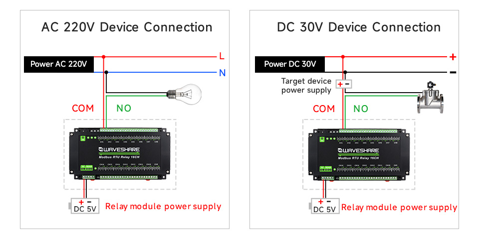
Relay Connection
Contact Rating Of The Onboard Relay Up To 10A 250VAC/30VDC
Directly Controlling 220VAC Home Appliances, Or Devices Below 30VDC
Applications

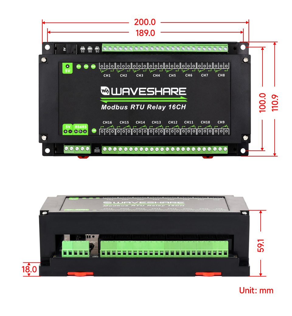
Outline Dimensions
What's in the box?
1 x Modbus RTU Relay 16CH
1 x US plug 5V 2A Power supply (with EU head adapter)
Resources
www.waveshare.com/wiki/Modbus_RTU_Relay_16CH

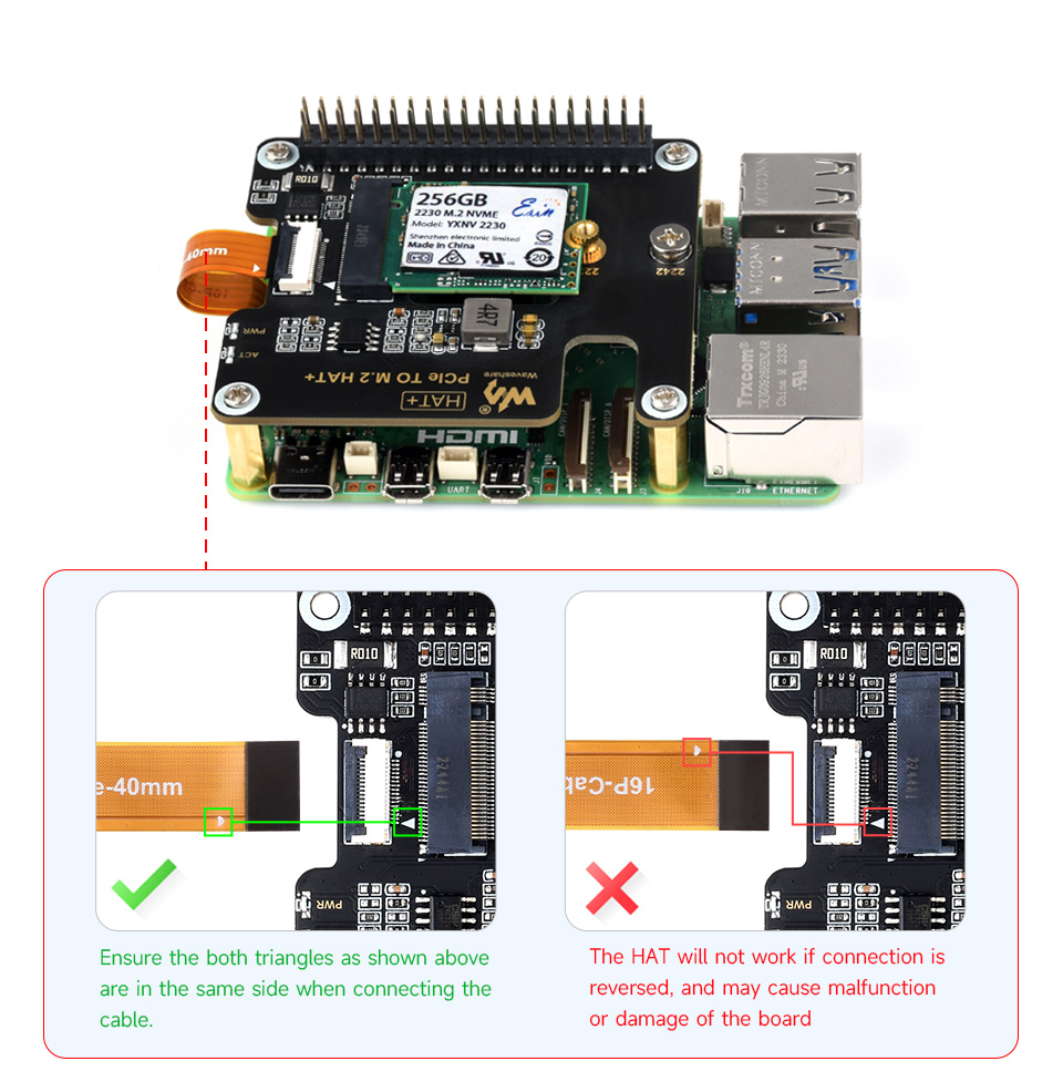
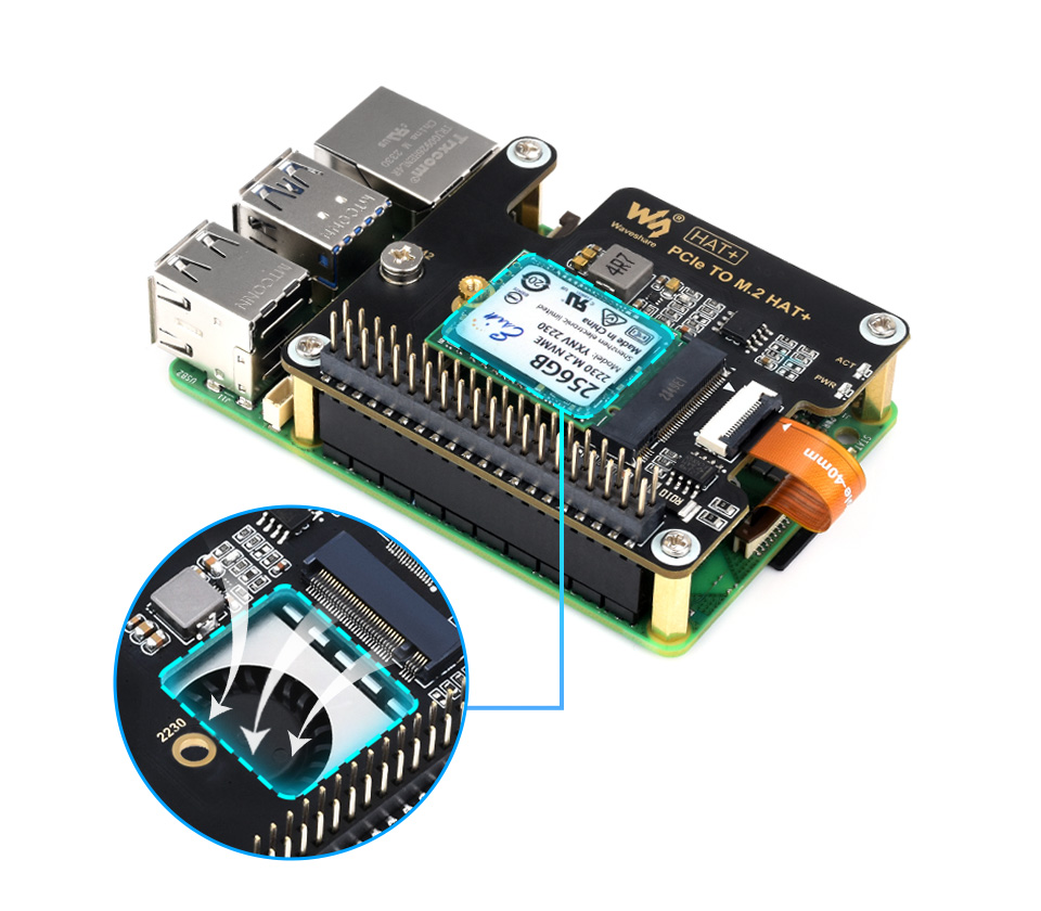
Designed for Raspberry Pi 5
Adapter For NVMe Protocol M.2 Solid State Drive, High-Speed Reading/Writing
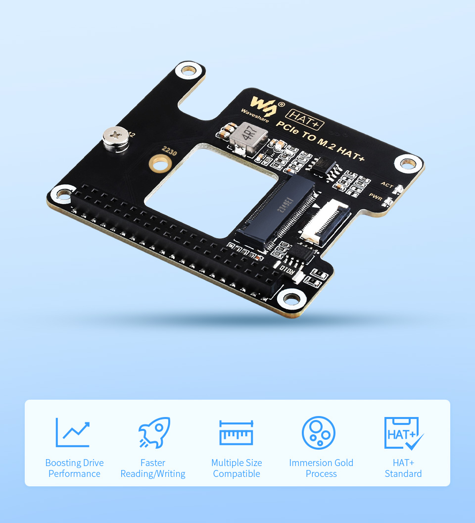
Based On 16PIN PCIe Interface Of Raspberry Pi 5
* for reference only, please refer to the Package Content for detailed part list
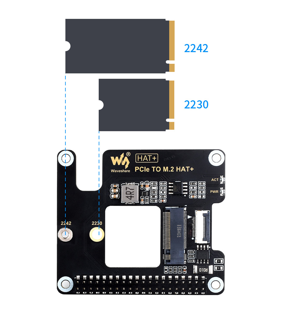
Compatible With 2230/2242 Size M.2 Solid State Drive
Supports Gen2 And Gen3 Modes, Supports Booting PI5 From Solid State Drive
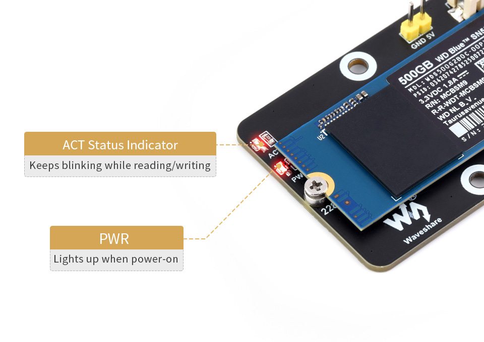
Easy To Monitor The Working Status
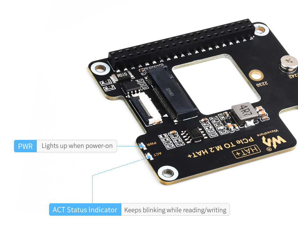
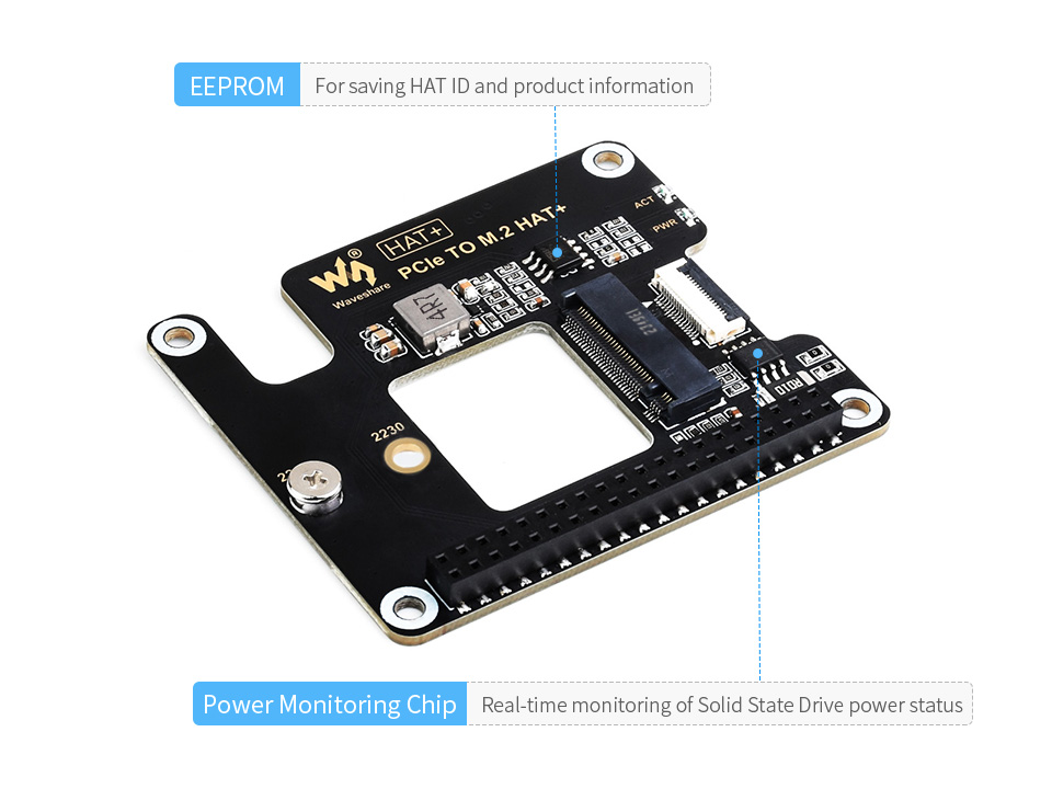
Onboard Power Monitoring Chip And EEPROM
Real-Time Monitoring Of Solid State Drive Power Status For More Stable Operation
Better Cooling Effect For Pi5 And Solid State Drive
* for reference only, the Raspberry Pi 5, cooling fan and Solid State Drive are not included
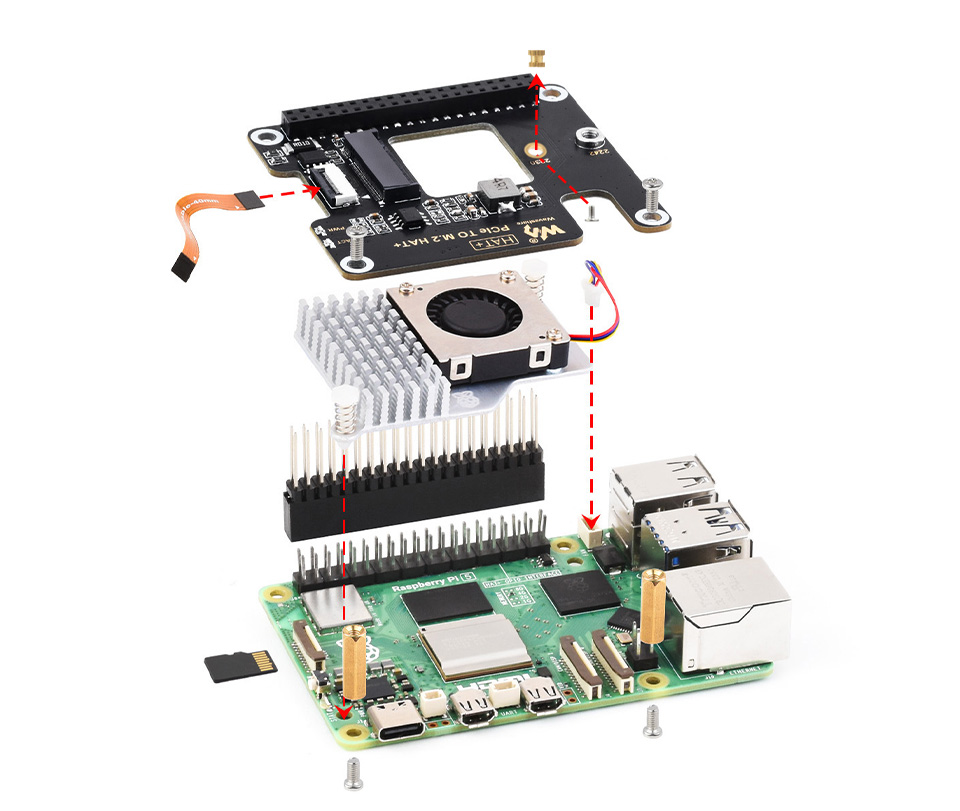
* for reference only, please refer to the Package Content for detailed part list
What's in the box?
1 x PCIe TO M.2 HAT+
1 x 2*20 Pin header
1 x 16P-Cable-40mm
1 x Standoff pack

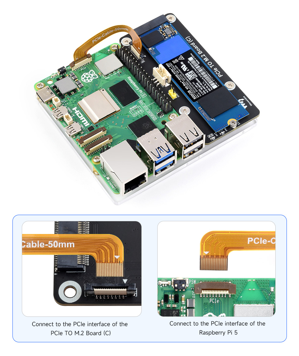
Designed for Raspberry Pi 5
Adapter For NVMe Protocol M.2 Solid State Drive, High-speed Reading/Writing, Improves Working Efficiency
Based on 16PIN PCIe Interface of Raspberry Pi 5
* for reference only, please refer to the Package Content for detailed part list
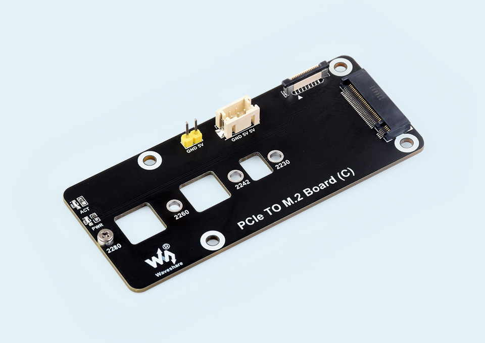
Adopts side-mounting solution to save space above the Raspberry Pi 5
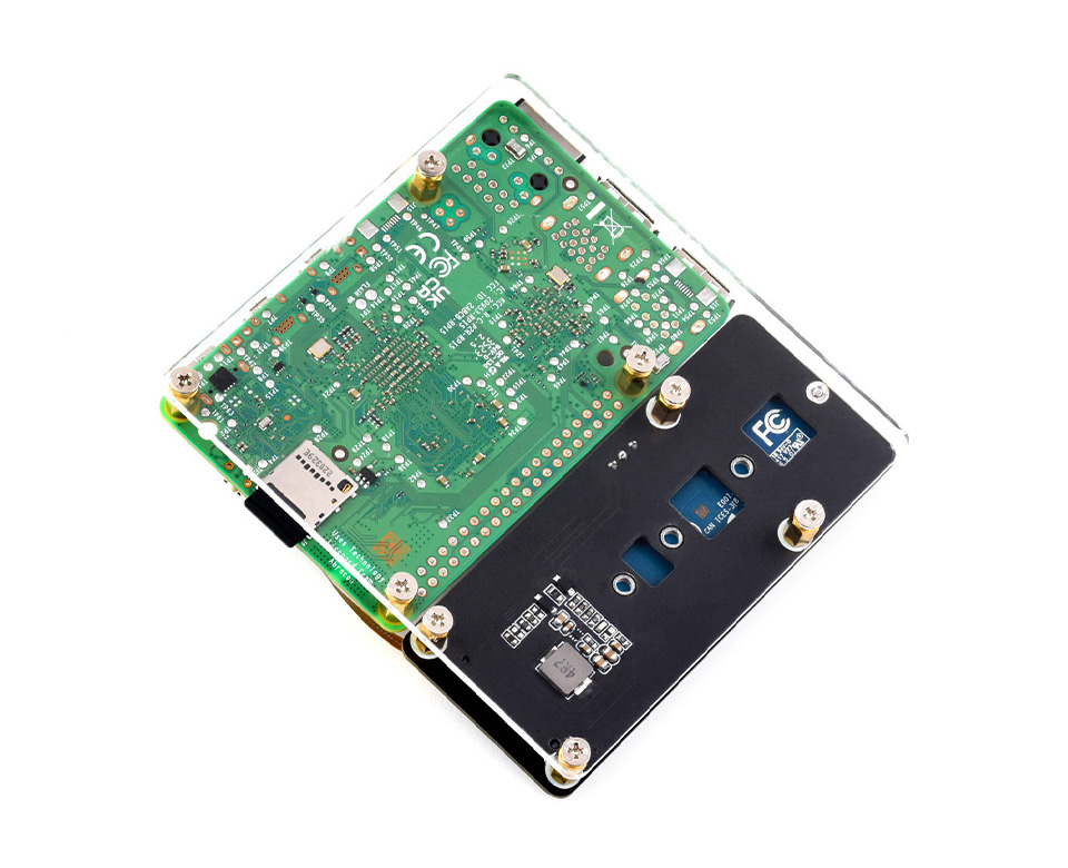
* for reference only, please refer to the Package Content for detailed part list
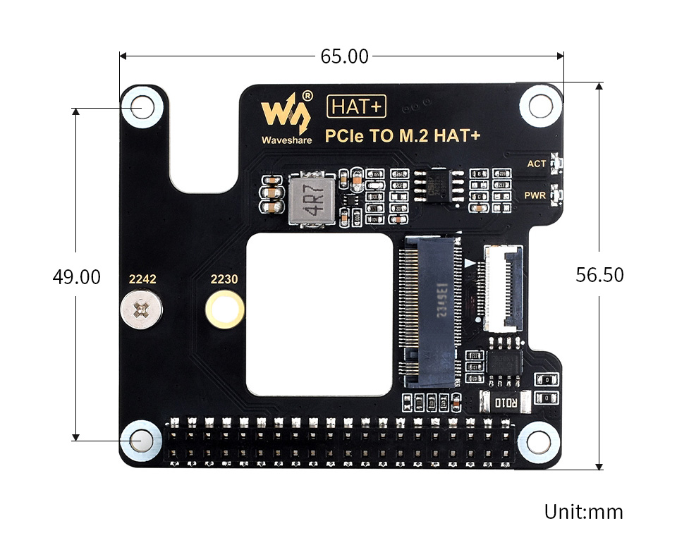
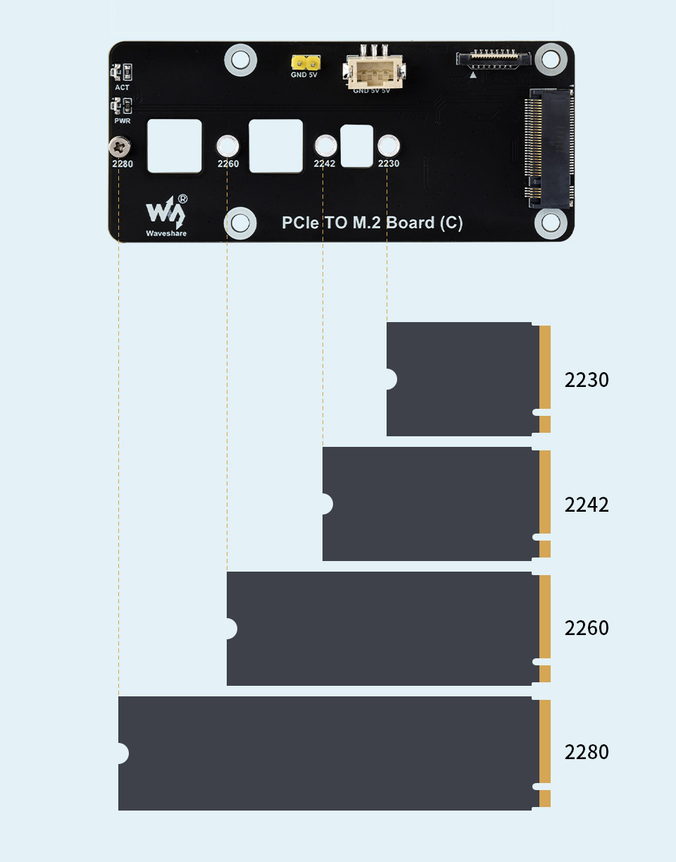
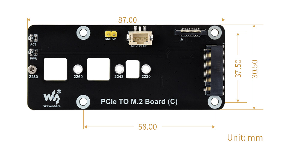
Compatible With 2230 / 2242 / 2260 / 2280 Size M.2 Solid State Drive
Supports Gen2 and Gen3 Modes, Supports Booting PI5 From Solid State Drive
Supports power supply via PCIe cable or 3PIN cable
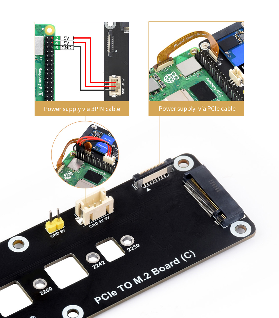
* Note: uses PCIe cable for power supply by default, you can add 3PIN cable in cases of insufficient power
Easy to monitor the Working Status
1 x PCIe TO M.2 Board (C)
1 x Transparent acrylic mounting plate
1 x PH2.0 3PIN cable ~5cm
1 x PCIe-Cable-50mm
1 x Standoff pack
You might also need a NVMe drive.

Needless to say, the Raspberry Pi is powerful enough in most cases, yet it's not that good at providing precise PWM output. You may have tried to control a robotic arm or a hexapod walker by using the Pi, but finally get frustrated due to the limited number of PWM outputs and the jittering servo. Now you get a new option to bring your ideas to life, we prepare this useful Servo Driver HAT for you.
Features
- Standard Raspberry Pi 40PIN GPIO extension header, supports Raspberry Pi series boards, Jetson Nano
- I2C controlled, using only 2 pins
- Up to 16-Channel servo/PWM outputs, 12-bit resolution for each channel (4096 scales)
- Integrates 5V regulator, up to 3A output current, can be powered from battery through VIN terminal
- Standard servo interface, supports common used servos
- Reserved I2C control pins, allows to work with other control boards
- Comes with development resources and manual (examples in python like Bluetooth/WiFi remote control)
Specifications
- Power supply: 5V (Pi connector) OR 6V~12V (VIN terminal)
- Servo voltage: 5V
- Logic voltage: 3.3V
- Driver: PCA9685
- Control interface: I2C
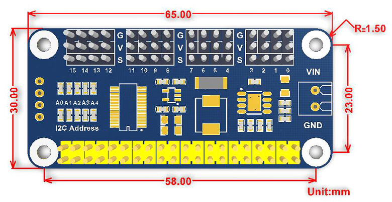
- Dimension: 65mm x 30mm
- Mounting hole size: 3.0mm
Dimensions
What's in the box?
1 x Servo Driver HAT
1 x RPi screws pack (2pcs)
Resources

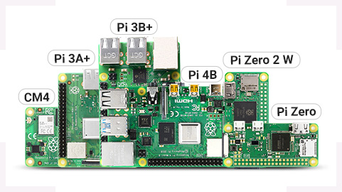
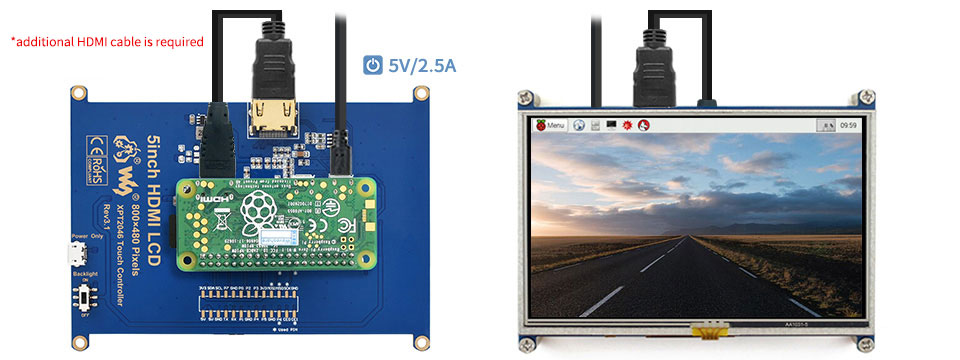
Additional HDMI Cable Required: Raspberry Pi Zero 2 W / Zero W / Zero
Driver Provided: supports Raspbian / Ubuntu / Kali / Retropie
Supports future version which is backward compatible
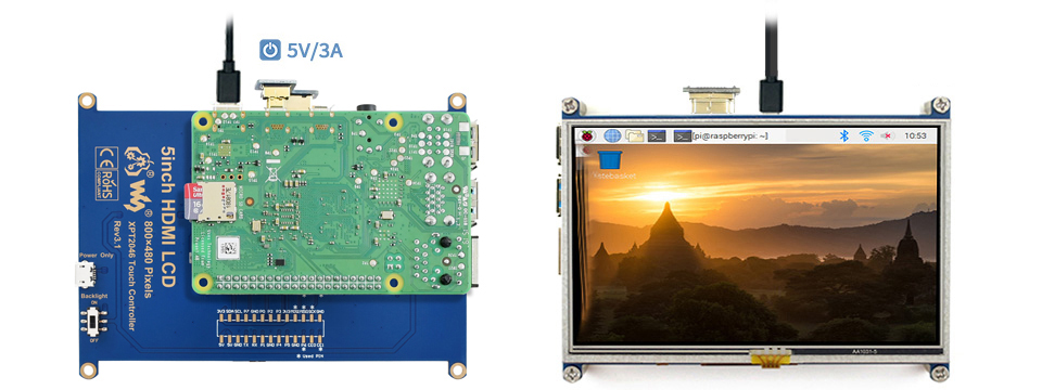
Working With Raspberry Pi 4
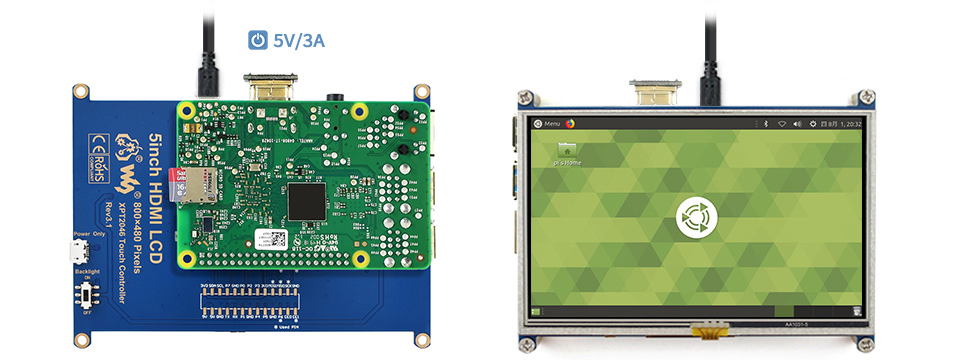
Working With Raspberry Pi 3B+
Working With Raspberry Pi Zero W
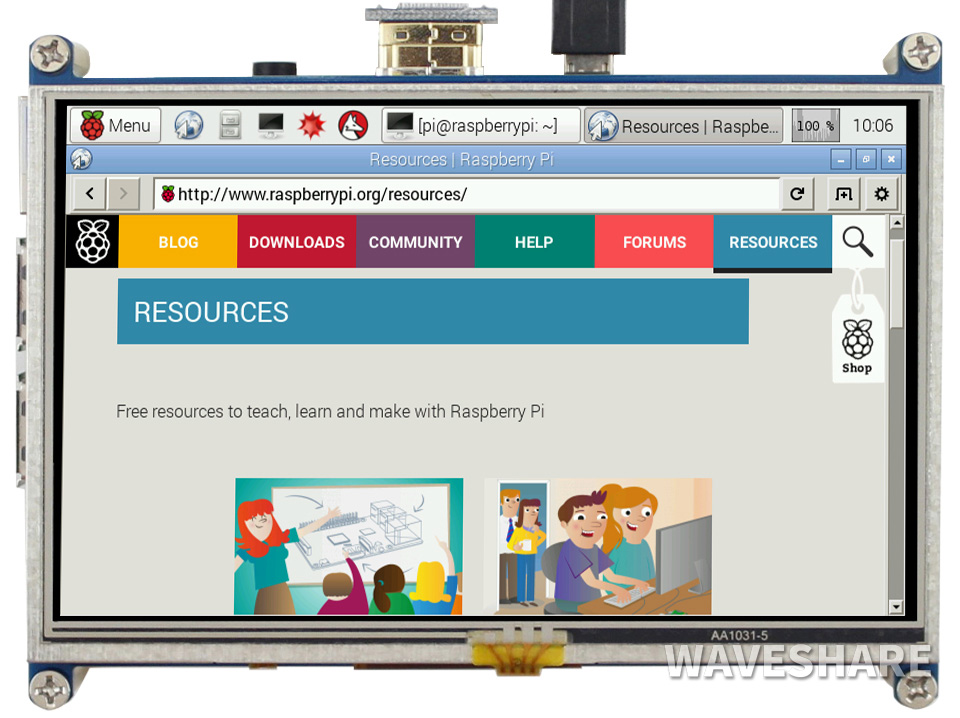
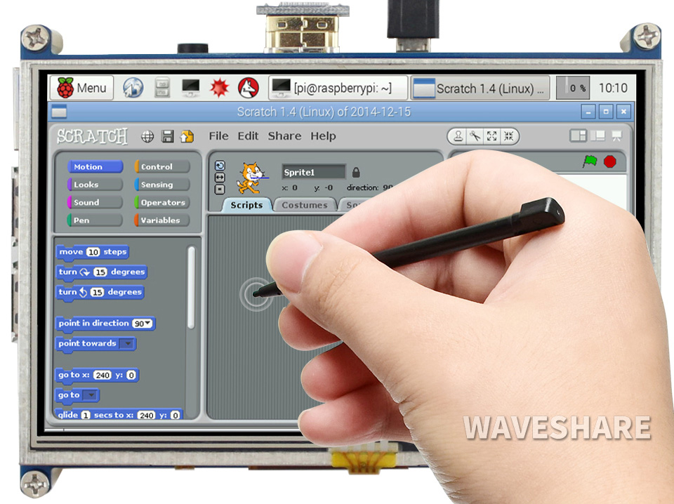
Comes With Touch Pen
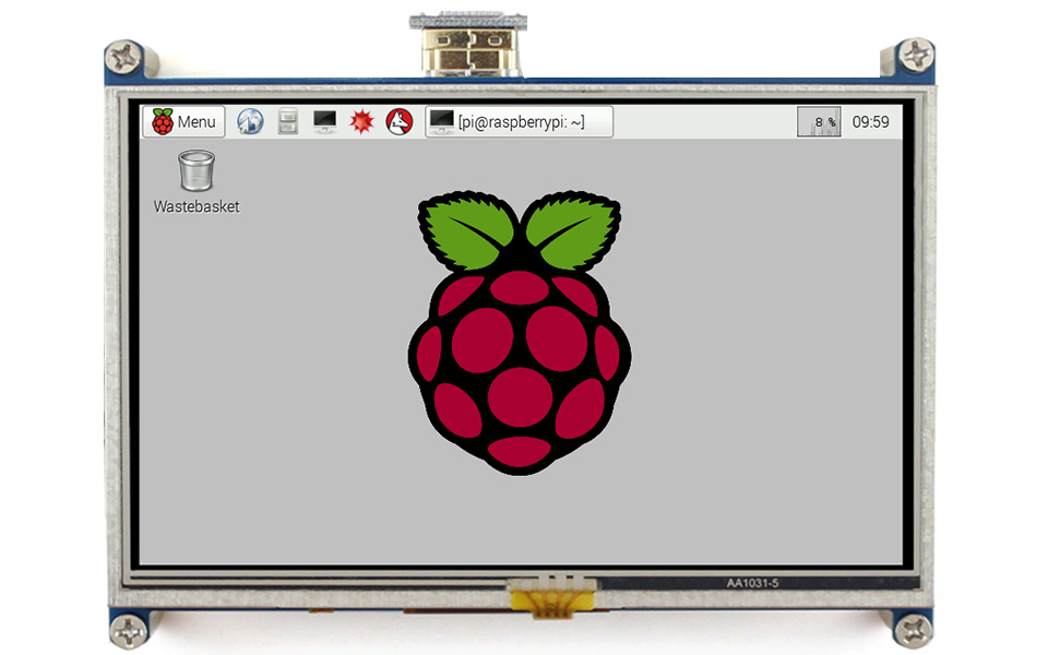
1 x 5inch HDMI LCD
1 x HDMI to micro HDMI connector
1 x HDMI connector
1 x Stylus
1 x RPi screws pack (4pcs)
Resrouces
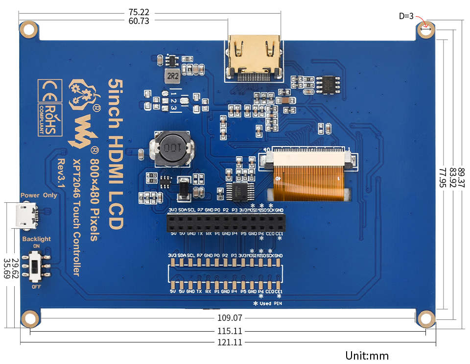
Wiki: 5inch_HDMI_LCD

Specifications
- Category: FFC
- Feature:
- flexible, easy wring
- EMI shielded, more stable transmission
- gold/tin-plating, anti-oxidation, capable of dealing with complex environment
- Exposed contact: 20 pin, 0.5mm pitch, opposite side
- Impendence control: 100 ± 10Ω
- Compliance: RoHS-compliant
- Dimension: 200mm x 10.7mm x 0.5mm
- For DIY HDMI Cable
What's in the box?
1 x DIY HDMI Cable: 0.2m FFC

Specifications
| MODEL |
(This product) | (Also available) | |
|---|---|---|---|
| MICROCONTROLLER | R7FA4 (32-bit ARM Cortex-M4) | R7FA4 (32-bit ARM Cortex-M4) | |
| ESP32-S3FN8 (Dual-core 32-bit Xtensa LX7) | |||
| CLOCK FREQUENCY | R7FA4: 48MHz | R7FA4: 48MHz | |
| ESP32-S3FN8: 240MHz | |||
| STORAGE | R7FA4: 256kB Flash, 32kB RAM | R7FA4: 256kB Flash, 32kB RAM | |
| ESP32-S3FN8: 384kB ROM, 512kB RAM, 8MB Flash | |||
| WIRELESS COMMUNICATION | None | 2.4GHz WiFi + Bluetooth LE | |
| OPERATING VOLTAGE | Options for 5V/3.3V, support more shields | ||
| POWER INPUT | 6~24V | ||
| RESET BUTTON | Lateral, easier to use when connecting with shield | ||
| IO PIN OUTPUT CURRENT | 8mA | ||
| DIGITAL PINS | 14 | ||
| ANALOG PINS | 6 | ||
| DAC | 2 | ||
| PWM | 6 | ||
| UART | 1 | ||
| I2C | 1 | ||
| SPI | 1 | ||
| CAN | 1 | ||
| DC JACK | Low profile, shields won't be blocked anymore while connecting | ||
| POWER OUTPUT HEADER | Provides 5V OR 3.3V power output and common-grounding with other boards | ||
| 5V POWER OUTPUT | Up to 2000mA Max, features higher driving capability | ||
| EXPERIMENTAL BOARD | Support, solder pad is provided for DIY interfaces to connect with experimental board | ||

What's On Board?
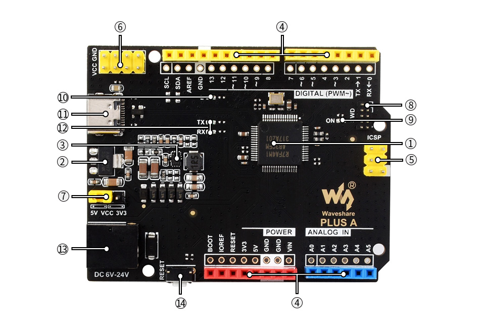
- R7FA4M1AB3CFM
- AMS1117-3.3
3.3V voltage regulator - MP8759
5V voltage regulator - Arduino interface
compatible with standard Arduino interface, adapting 2.54 pitch solder pad, can be directly connected to experimental board - ICSP interface
- Power output header
3.3V OR 5V, voltage level configured by the onboard power configuration switch, used as power output and common-grounding with other boards
- Power configuration
for configuring R7FA4 PLUS A operating voltage - SWD indicator
- Power indicator
- User LED
- USB Type-C connector
for uploading program OR serial port debugging - Serial port RX/TX indicators
- DC input
6V ~ 24V - Reset button
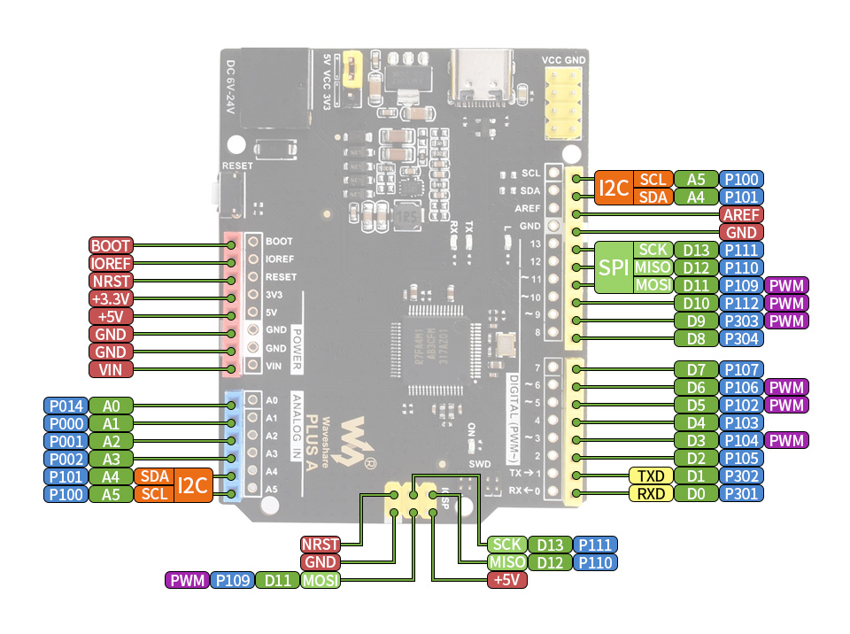
Pinout Definition
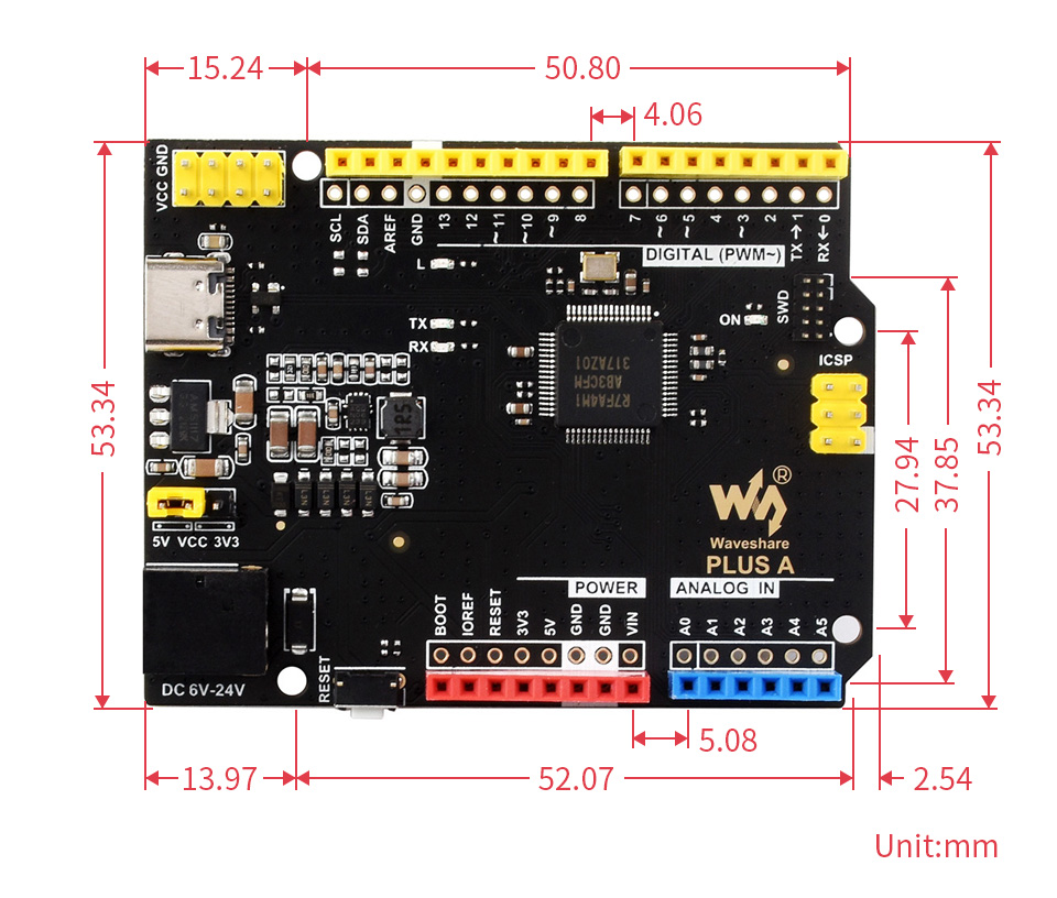
Outline Dimensions
What's in the box?
1 x Arduino Uno Rev 4 compatible
1 x USB Type-A to Type-C cable

Specifications
| MODEL | (This product) |
(Also available) | |
|---|---|---|---|
| MICROCONTROLLER | R7FA4 (32-bit ARM Cortex-M4) | R7FA4 (32-bit ARM Cortex-M4) | |
| ESP32-S3FN8 (Dual-core 32-bit Xtensa LX7) | |||
| CLOCK FREQUENCY | R7FA4: 48MHz | R7FA4: 48MHz | |
| ESP32-S3FN8: 240MHz | |||
| STORAGE | R7FA4: 256kB Flash, 32kB RAM | R7FA4: 256kB Flash, 32kB RAM | |
| ESP32-S3FN8: 384kB ROM, 512kB RAM, 8MB Flash | |||
| WIRELESS COMMUNICATION | None | 2.4GHz WiFi + Bluetooth LE | |
| OPERATING VOLTAGE | Options for 5V/3.3V, support more shields | ||
| POWER INPUT | 6~24V | ||
| RESET BUTTON | Lateral, easier to use when connecting with shield | ||
| IO PIN OUTPUT CURRENT | 8mA | ||
| DIGITAL PINS | 14 | ||
| ANALOG PINS | 6 | ||
| DAC | 2 | ||
| PWM | 6 | ||
| UART | 1 | ||
| I2C | 1 | ||
| SPI | 1 | ||
| CAN | 1 | ||
| DC JACK | Low profile, shields won't be blocked anymore while connecting | ||
| POWER OUTPUT HEADER | Provides 5V OR 3.3V power output and common-grounding with other boards | ||
| 5V POWER OUTPUT | Up to 2000mA Max, features higher driving capability | ||
| EXPERIMENTAL BOARD | Support, solder pad is provided for DIY interfaces to connect with experimental board | ||
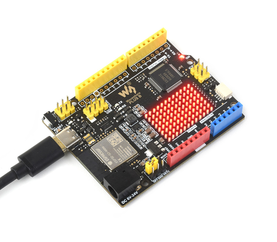
Onboard 12×8 Red LED Matrix
Supports Customisation Of Display Effect
What's On Board?
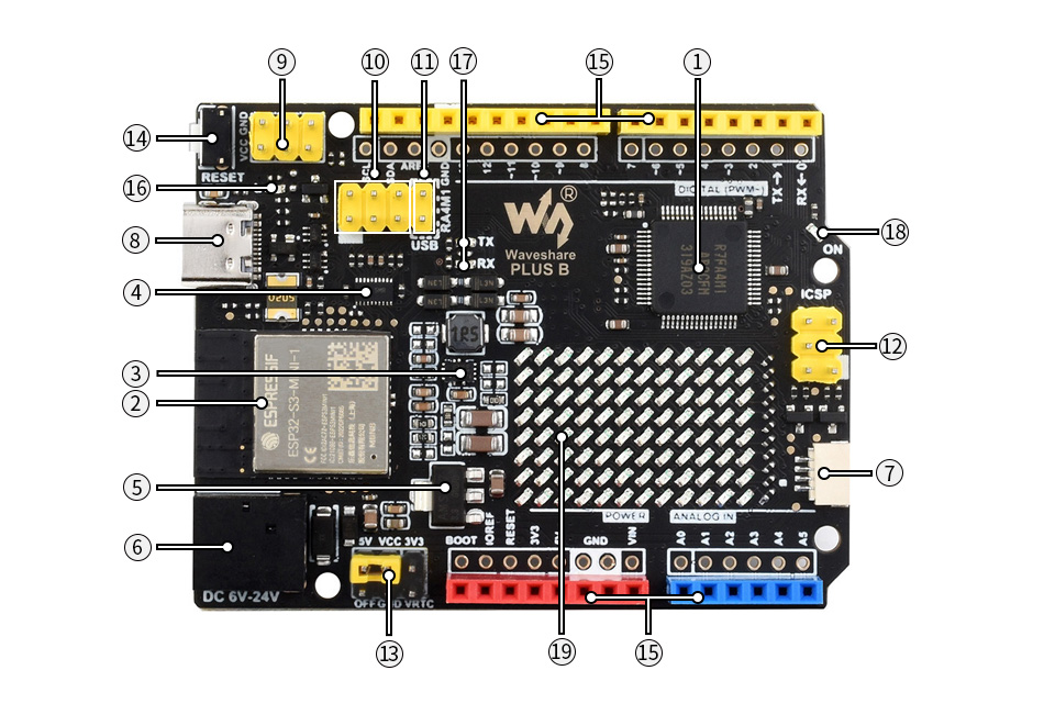
- R7FA4M1AB3CFM
- ESP32-S3-MINI-1 module
- MP8759
5V voltage regulator - TXB0108DQSR
voltage translator, for communication between R7FA4 and ESP32-S3 - AMS1117-3.3
3.3V voltage regulator - DC input
6V ~ 24V - Qwiic connector
for connecting I2C device of Qwiic Eco - USB Type-C connector
for uploading program OR serial port debugging - Power output header
3.3V OR 5V, voltage level configured by the onboard power configuration switch, used as power output and common-grounding with other boards
- ESP32-S3 pinheader
for ESP32-S3-MINI-1 firmware downloading - USB communication selection
- ICSP interface
- Power configuration
for configuring R7FA4 PLUS B operating voltage - Reset button
- Arduino interface
compatible with standard Arduino interface, adapting 2.54 pitch solder pad, can be directly connected to experimental board - User LED
- Serial port RX/TX indicators
- Power indicator
- 12×8 LED matrix
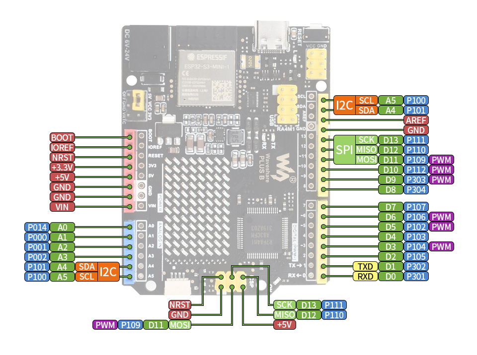
Pinout Definition
What's in the box?
1 x Arduino Uno Rev 4 wifi compatible
1 x USB Type-A to Type-C cable
Resources

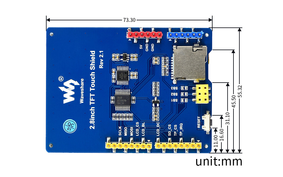
- Resistive touch screen TFT LCD, 2.8inch, 320x240 resolution
- Standard Arduino interface, compatible with development boards like : Arduino UNO, Leonardo, UNO PLUS, NUCLEO, XNUCLEO
- Onboard stand-alone touch controller, better touching than solutions that use AD pins directly for touch control
- Micro SD slot, provides an easy way to store photos for displaying
- Controlled via SPI, only a few Arduino pins are used
- Backlight adjustable by program, lower power consumption
Key Parameters
| LCD TYPE | TFT |
|---|---|
| LCD INTERFACE | SPI |
| LCD CONTROLLER | ST7789 |
| TOUCH SCREEN TYPE | Resistive |
| TOUCH SCREEN CONTROLLER | XPT2046 |
| COLORS | RGB, 65K colours |
| RESOLUTION | 320x240 (Pixel) |
| I/O VOLTAGE | 3.3V/5V |
Interface
| ARDUINO PIN | SYMBOL | DESCRIPTION |
|---|---|---|
| D3 | TP_IRQ | Touch panel interrupt |
| D4 | TP_CS | Touch panel chip select |
| D5 | SD_CS | Micro SD card chip select |
| D7 | LCD_DC | LCD data/command selection |
| D9 | LCD_BL | LCD backlight control |
| D10 | LCD_CS | LCD chip select |
| D11 | MOSI | SPI data input |
| D12 | MISO | SPI data output |
| D13 | SCLK | SPI clock |
External Dimensions
Resources

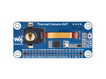
80×62 Pixels IR Array
Four versions are available: options for HAT version with Raspberry Pi 40PIN GPIO header and USB version with Type-C port. Also provides basic version and wide angle version with 45° / 90° FOV.
Key features include:
- Adopts the hybrid technology of microbolometer and thermopile, 80x62 array pixels
- Continuous operation and thermal imaging video stream due to shutterless design
- Noise Equivalent Temperature Difference (NETD) 150mK RMS@1Hz refresh rate
- Up to 25FPS (Max) thermal imaging video stream output
- Comes with online resources and manuals (Python demo for Raspberry Pi, Android/Windows host computer and user manual, etc.)
Main applications:
- High precision long-term non-contact temperature online monitoring
- IR thermal imaging devices, IR thermometers
- Smart home, intelligent building, intelligent lighting
- Industrial temperature control, security & safety, intrude/motion detection
- Small Target Thermal Analysis, Heat Trend Analysis and Solutions
Onboard 40PIN GPIO header
| POWER SUPPLY | 5V |
|---|---|
| OPERATING CURRENT | 61mA@5V |
| WAVELENGTH RANGE | 8~14μm |
| OPERATING TEMPERATURE | -20~85℃ |
| TARGET TEMPERATURE | -20~400℃ |
| REFRESH RATE | 25 FPS (Max) |
| FOV | Basic version: 45°(H)×45°(V) |
| NOISE EQUIVALENT TEMPERATURE DIFFERENCE | 150mK |
| MEASURING ACCTRACY | ±2℃ (ambient temp. 10~70℃) |
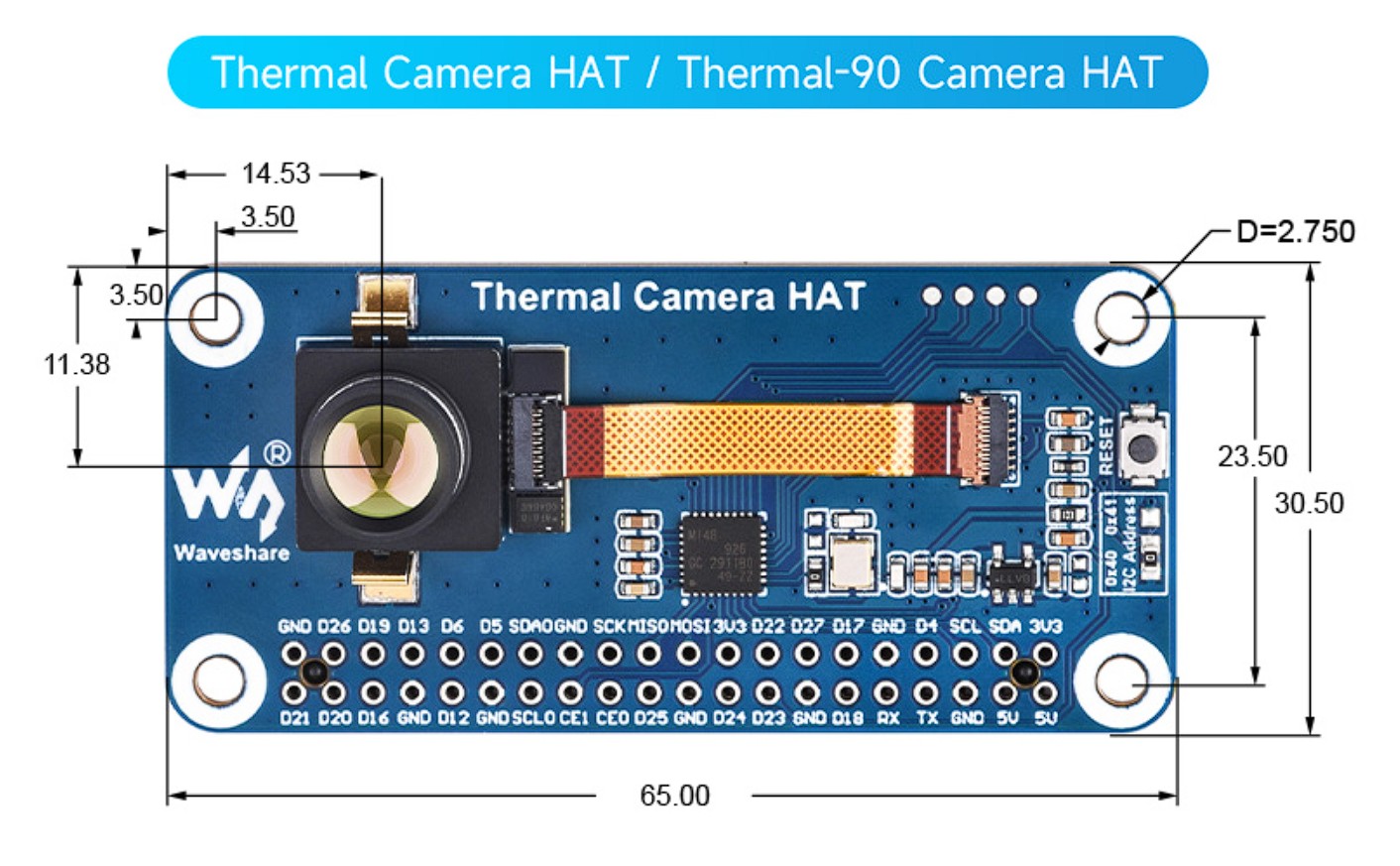
| DIMENSIONS | Thermal Camera HAT / Thermal-90 Camera HAT: 65.0×30.5mm |
| Thermal USB Camera / Thermal-90 USB Camera: 62.0×13.0mm |
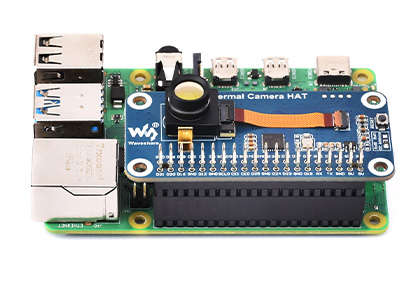
With Onboard 40PIN GPIO Header
Compatible With Raspberry Pi Boards
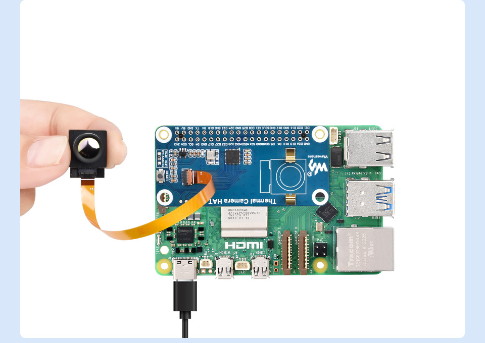
Directly connect to Raspberry Pi ZERO
What's in the box?
1 x 40PIN female header
1 x FPC 15 PIN cable 0.3mm pitch ~100mm
1 x Screws pack