
WaveShare


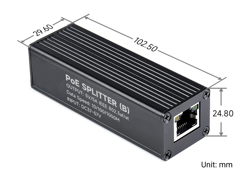
Industrial Gigabit PoE Splitter, 5V 5A Type-C power output. IEEE 802.3af/at-compliant Gigabit Ethernet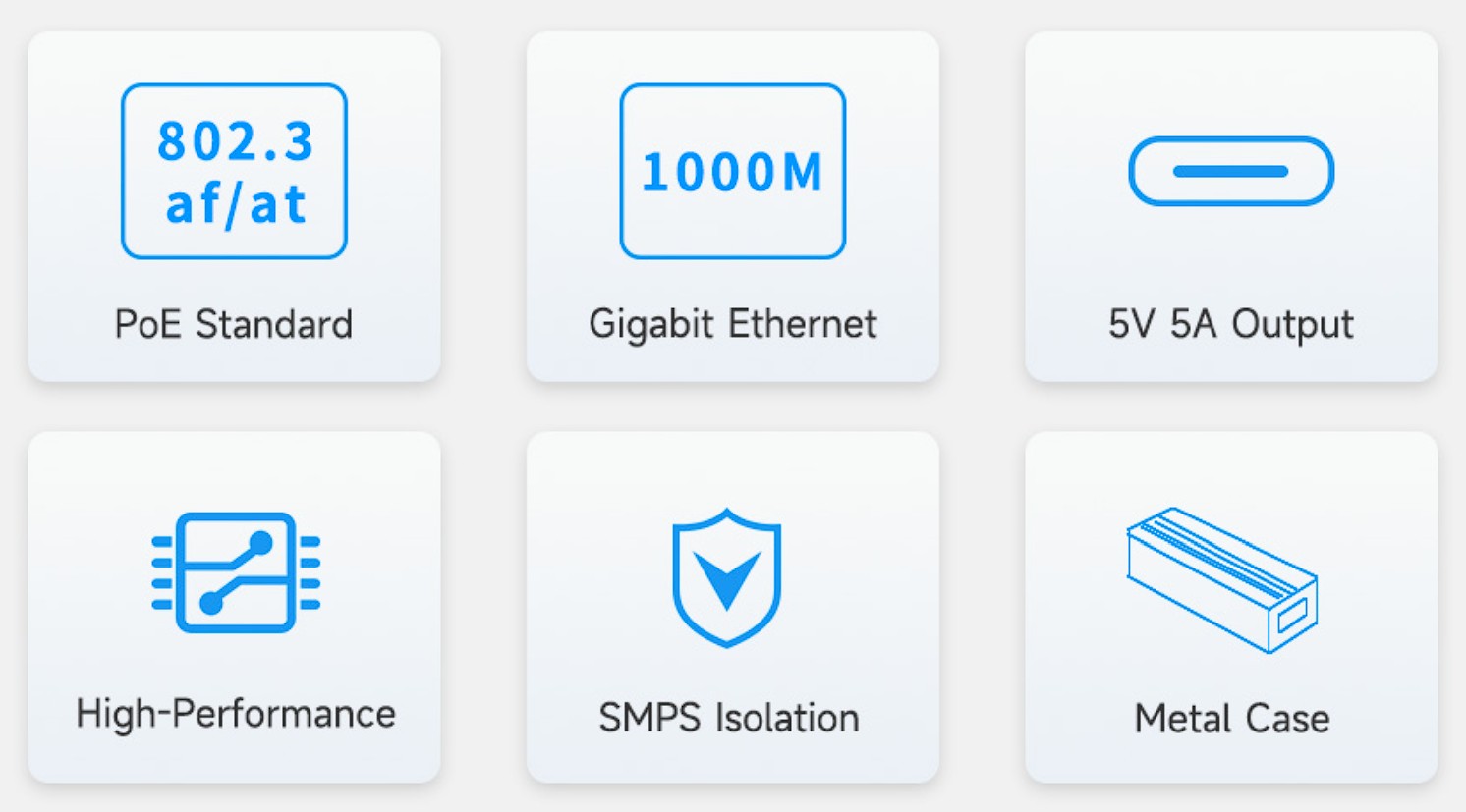
Features at a glance
- 10/100/1000Mbps auto-negotiation Ethernet port
- 802.3af/at-compliant PoE (Power over Ethernet) standard
- Isolated SMPS (Switching Mode Power Supply), effectively protecting the powered device
- 5V DC output, suitable for powering Raspberry Pi and other small-scale network devices
- Black dull-polish metal case, sturdy and rugged, higher protection level, better heat dissipation
Specifications
| Power supply | supports 1/2(+); 3/6(-); 4/5(+); 7/8(-) powering |
|---|---|
| PoE input voltage | 37V ~ 57V |
| Type-C output | 5V 5A (MAX) |
| Cable | Cat-5 UTP |
| Standard | IEEE 802.3 af/at PoE Ethernet |
| Data rate | 10/100/1000Mbps |
| LED indicator | PoE power input indicator |
| Dimensions | 86 × 30 × 25mm (l × w × h) |
| Operating temperature | -40℃ ~ 85℃ |
MPS Control Chip Solution
High-efficiency, Safer And More Stable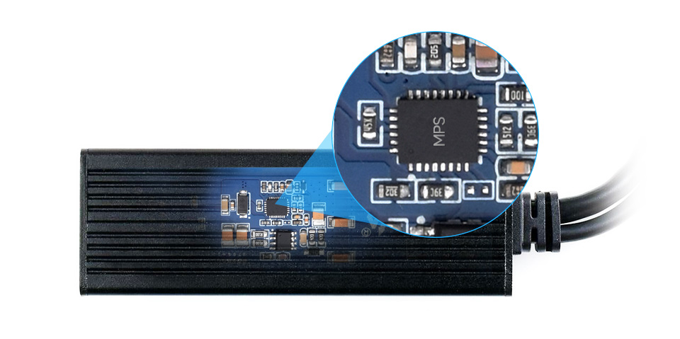
Isolated circuit protection, effectively protecting the powered device
Industrial grade protection case
aluminum alloy case, sturdy and rugged, higher protection level, better heat dissipation 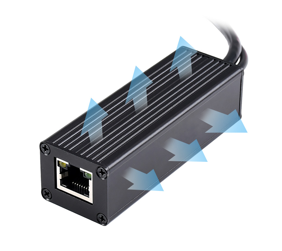
Powering the Raspberry Pi or other 5V-powered network devices by PoE switch
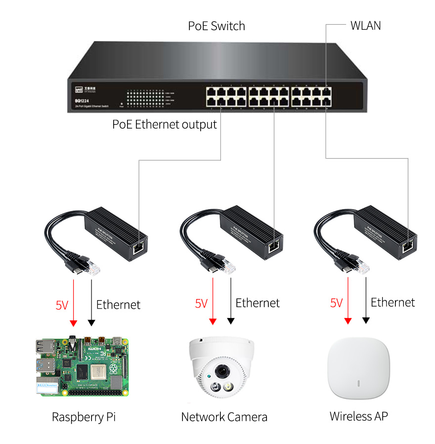
for reference ONLY, Raspberry Pi and switch are NOT included.
What's in the box?
1 x POE splitter
Resources
Wiki: POE-SPLITTER-TYPE-C (Docs for the 2.5A unit. 5A docs not available yet)

Specifications
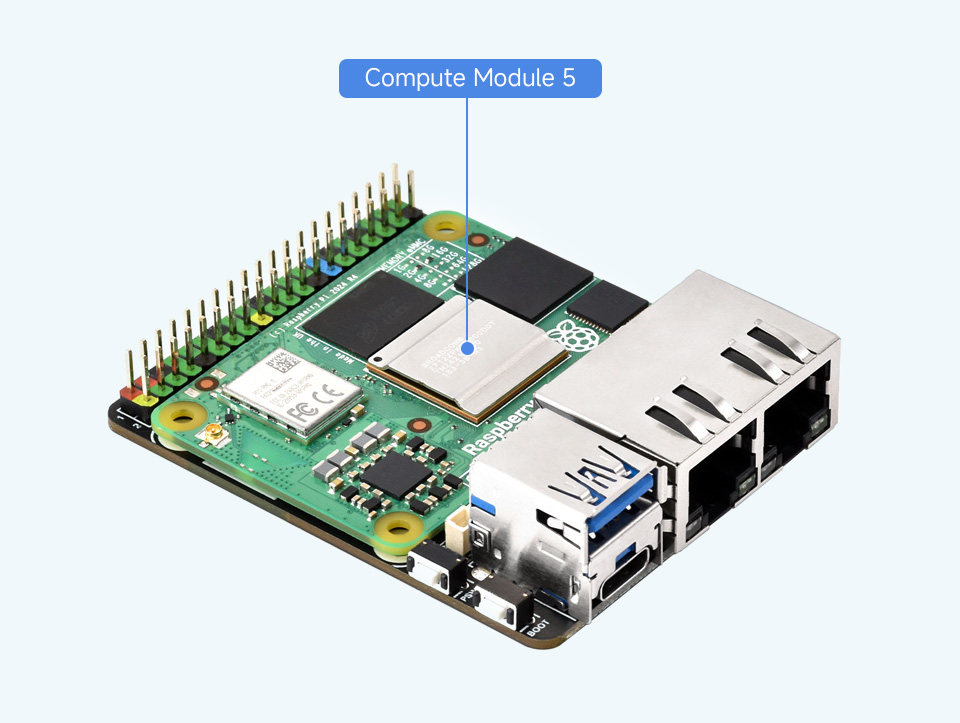
- CM5 socket: suitable for all variants of Compute Module 5
- Networking: Dual Gigabit Ethernet RJ45 connectors
- USB: USB 3.0 port
- PIN HEADER: Raspberry Pi 40PIN GPIO header
- Storage: TF card socket for Compute Module 5 Lite (without eMMC) variants
- Fan header: 4-wire SH1.0 port, allows speed adjustment and measurement, 5V
- Power input: 5V, Type-C interface
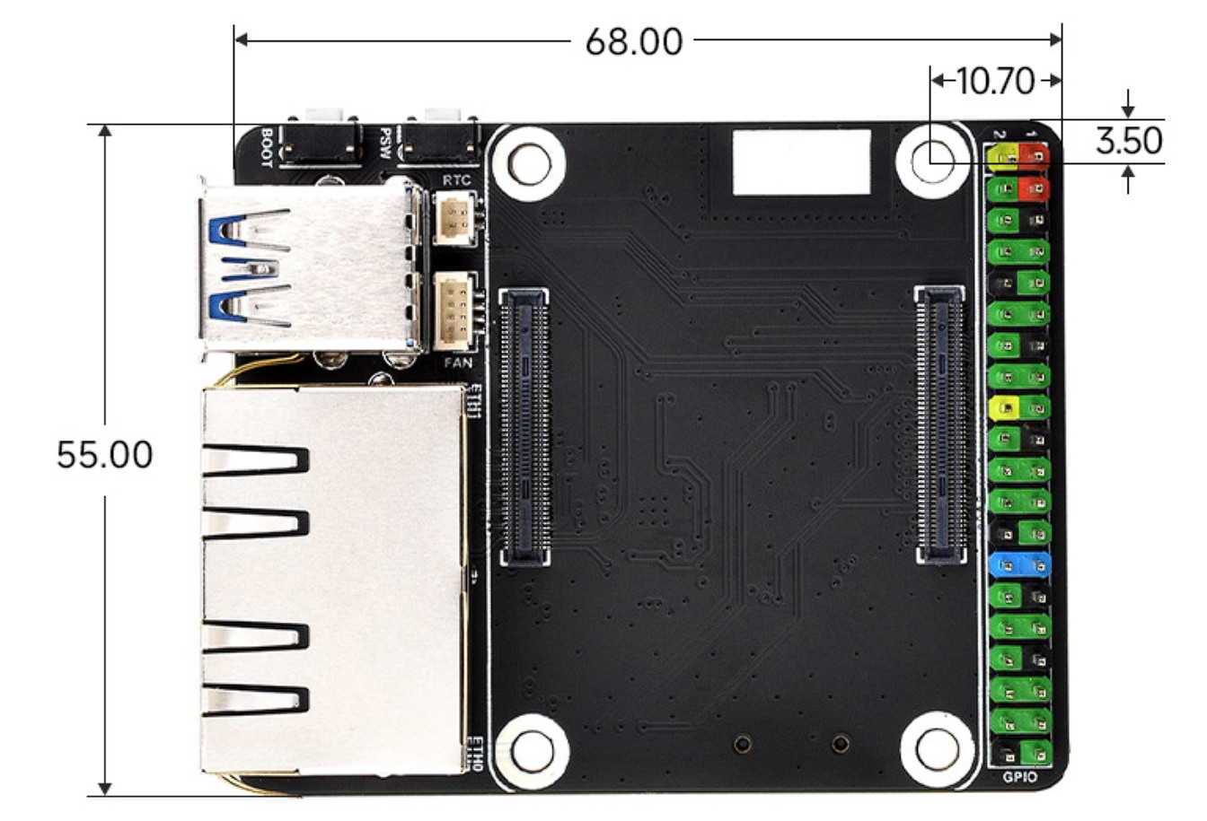
- Dimensions: the base board: 55.0 × 68.0mm
Connecting with Compute Module 5(Not Included)
Standard CM5 socket and 40PIN GPIO header
Suitable for Compute Module 5 Lite/eMMC series module
What's On Board
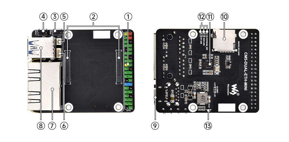
- 40PIN GPIO header
for connecting sorts of HAT - CM5 socket
suitable for all variants of Compute Module 5 - PSW button
- BOOT button
- RTC battery header
for connecting rechargeable RTC battery - FAN header
for connecting cooling fan, allows speed adjustment and measurement - RJ45 Gigabit Ethernet ports
Dual RJ45 Gigabit Ethernet ports, 10/100/1000M compatible
ETHERNET 0: CM5 original network port
ETHERNET 1: PCIe extended network port
- USB3.2 Gen1 Type-A port
for connecting sorts of USB devices - Type-C port
5V power supply, or used for eMMC programming - TF card slot
for connecting a TF card with pre-burnt image (Lite variant ONLY) - RTL8111H
Gigabit NIC chip - SYSTEM switch
EEPROM_WP: Prevent EEPROM from being overwritten
WiFi_DIS: WiFi disabled, only for CM5 versions with wireless
BT_DIS: Bluetooth disabled, only for CM5 versions with wireless - Indicators
Red light: indicating the power supply status of Raspberry Pi
Green light: indicating the working status of Raspberry Pi
Outline dimensions
What's in the box?
1 x Base board for CM5
Resources

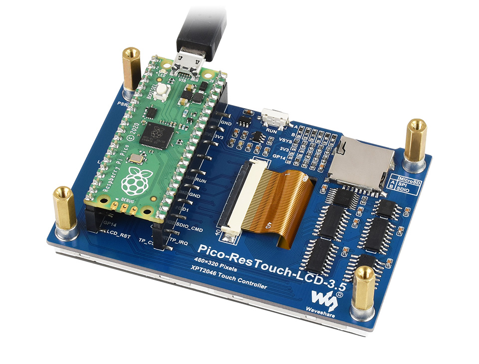
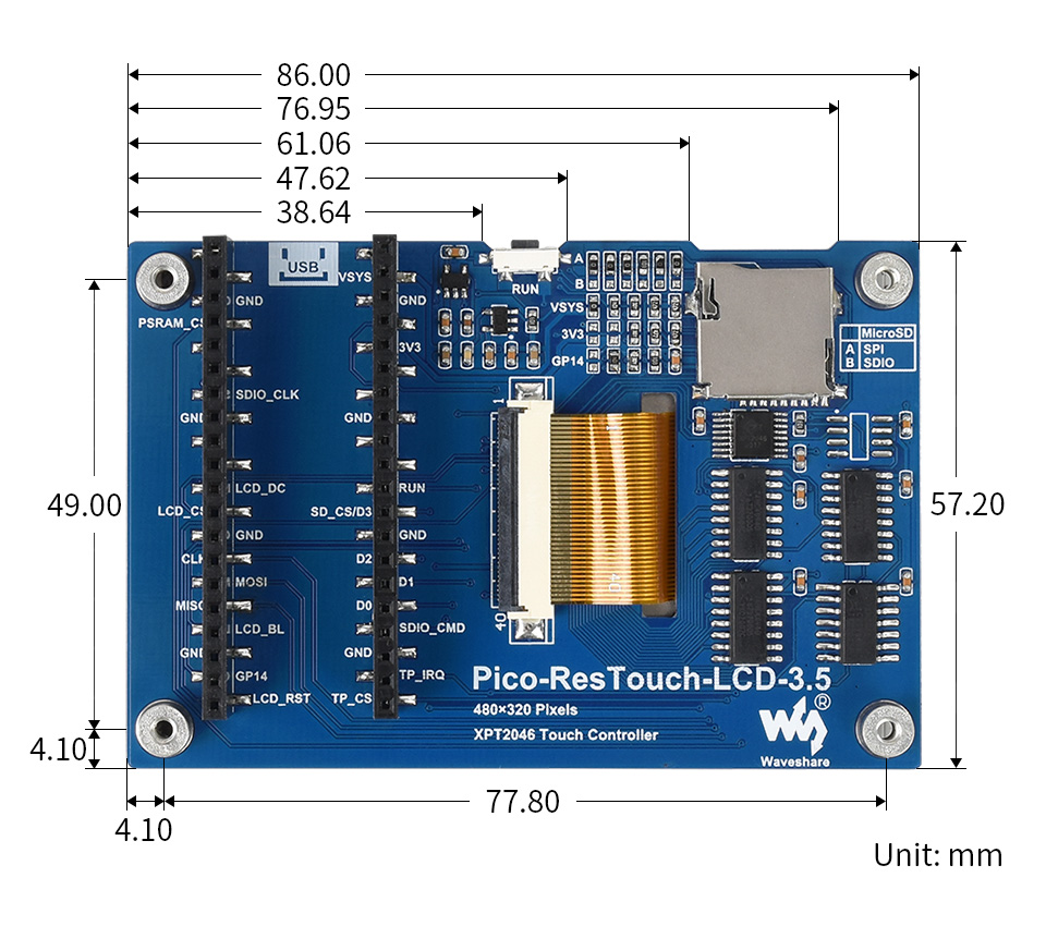
Resistive touch controller XPT2046, ILI9488 driver, using SPI bus
Comes with Raspberry Pi Pico C/C++ and MicroPython Demo
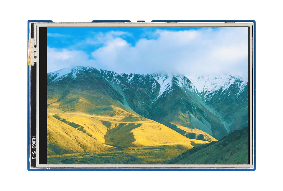
- Size: 3.5"
- Resolution: 480×320
- Display Color: 65K Colors
- Display Panel: IPS
- Touch Type: Resistive
- Interface: SPI
- Driver/Controller: ILI9488/XPT2046
- 480×320 resolution, IPS screen, 65K colors, clear and colorful displaying effect
- Dedicated touch controller, bringing more smooth touching effect than AD-controlled solutions
- MicroSD card slot for storing images and direct displaying them easily
- Programmable backlight control, power saving
- Comes with development resources and manual (Raspberry Pi Pico C/C++ and MicroPython examples)
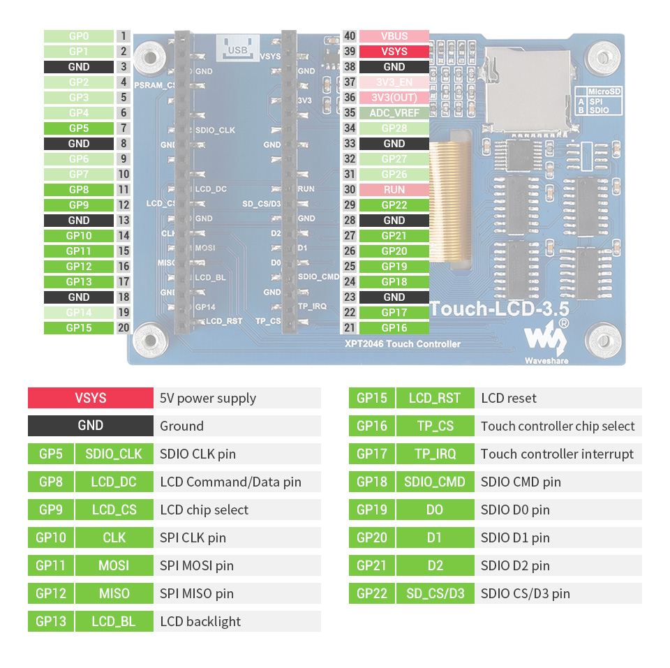
| Operating voltage | 5V | Resolution | 480×320 pixels |
|---|---|---|---|
| Communication Interface | SPI | Display size | 73.44 × 48.96 mm |
| Display Panel | IPS | Pixel size | 0.153 × 0.153 mm |
| Driver | ILI9488 | Dimensions | 86.00 × 57.20 mm |
| Touch Controller | XPT2046 |
Onboard female pin header for direct attaching to Raspberry Pi Pico
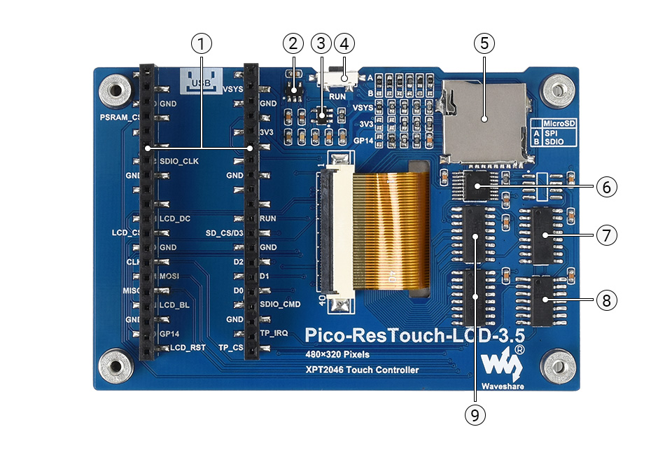
- Rapsberry Pi Pico header
- CAT6219
LCD backlight power chip - RT9193-33
3.3V linear voltage regulator - Pico reset button
- MicroSD card slot
- XPT2046 resistive touch controller
- 74HC4040 counter chip, for clock frequency division
- 74HC04D inverter chip
- 74HC4094 serial data to parallel data converter

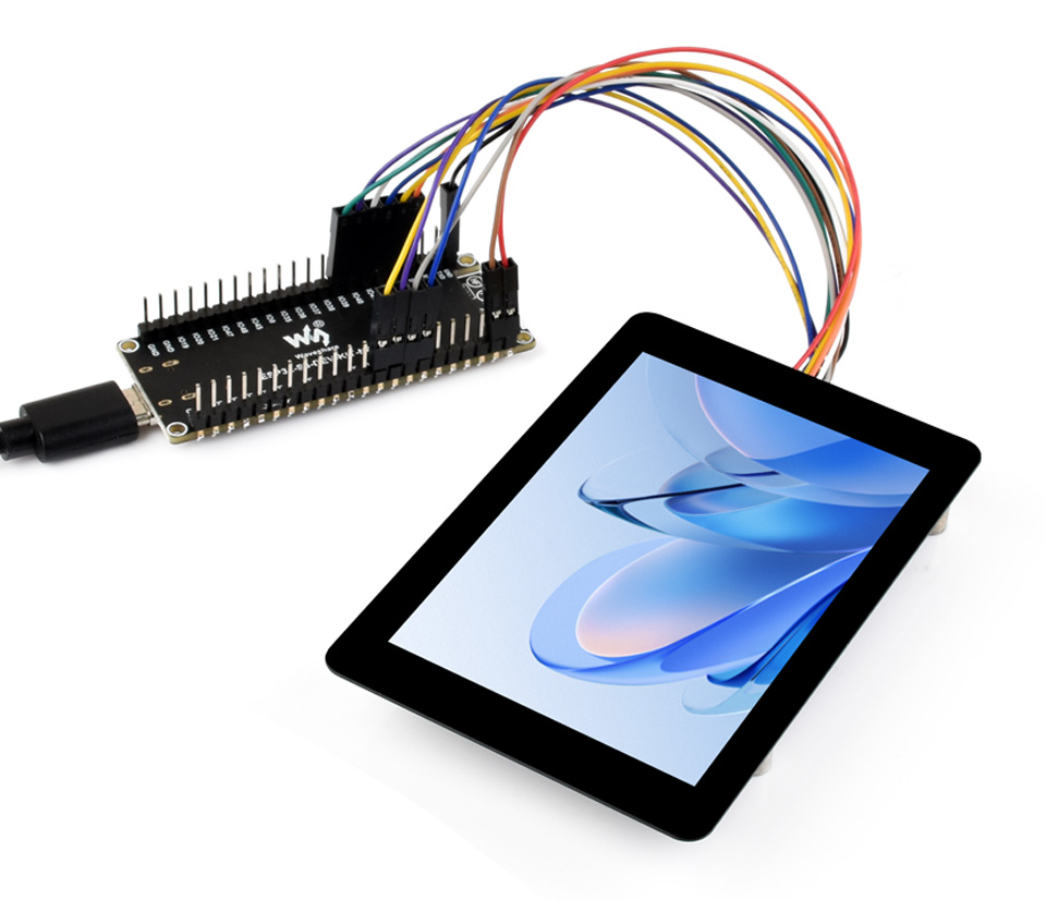
Embedded ST7796S driver and GT911 capacitive touch control chip
Comes with examples for Raspberry Pi / Raspberry Pi Pico / ESP32 / Arduino
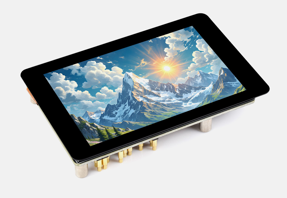
- Size: 3.5"
- Resolution: 320×480
- Display Color: 262K
- Display Panel: IPS
- Display Driver: ST7796S
- Display Interface: SPI
- Touch Driver: GT911
- Touch Interface: I2C
- Touch Type: Capacitive
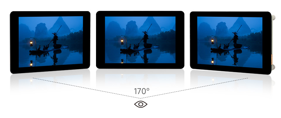
- Touch Points: 5-Point
- Viewing Angle: 170°
- Touch Panel: Toughened Glass
- Certification 1: CE
- Certification 2: ROHS
- PCB Process: Immersion Gold
- 262K color display with 320 × 480 resolution for excellent visual effects
- High touch screen transmittance, fast response, sensitive touch, and long lifetime
- Embedded with ST7796S driver chip and GT911 capacitive touch control chip, using SPI and I2C communication respectively, minimizes required IO pins
- Supports Pigo pin communication and GH1.25 13PIN cable connection
- Adopts Immersion Gold process, nice looking, with better durability
- Comes with online development resources and manual (examples for Raspberry Pi / Raspberry Pi Pico / ESP32 / Arduino)
| Operating Voltage | 5V | Logic level | 3.3V |
|---|---|---|---|
| Display Driver | ST7796S | Touch Driver | GT911 |
| Display Interface | 4-wire SPI | Touch Interface | I2C |
| Display Panel | IPS | Display size | 3.5inch |
| Touch Type | Capacitive | Touch Points | 5-point touch |
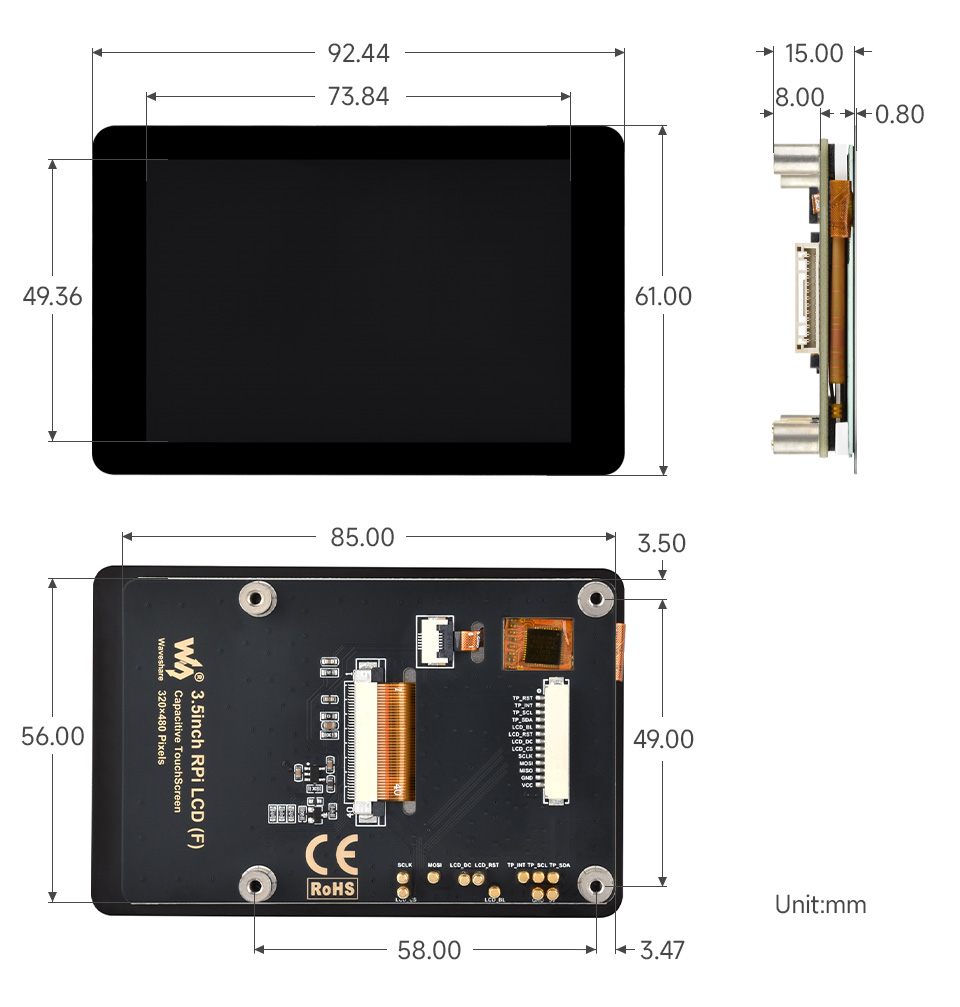
| Display Size | 49.36 × 73.84mm | Touch panel Size | 61.00 × 92.44mm |
Embedded with ST7796S Driver Chip And GT911 Capacitive Touch Control Chip

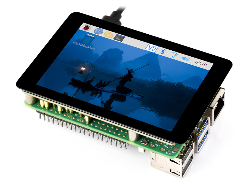
Highly compatible with Raspberry Pi desktop OS, supports smooth and stable operation
Excellent Display Performance, 262K color, wide viewing angle
Comes With Demos And Manuals For Raspberry Pi / Raspberry Pi Pico / ESP32 / Arduino
More Convenient For Development And Integration, with High Expansibility
Options For GH1.25 13PIN Connector Or Pigo Pin For Connecting The LCD To The Host Board
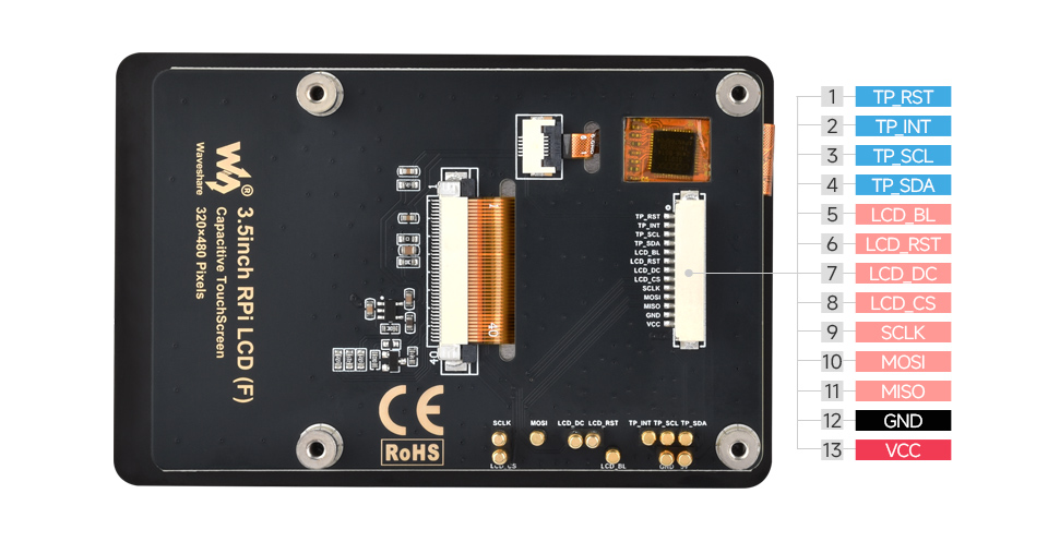
| Pin | Description | 13PIN Pin No. |
|---|---|---|
| TP_RST | Touch panel Reset pin, low active | 1 |
| TP_INT | Touch panel Interrupt pin | 2 |
| TP_SCL | Touch panel Clock pin | 3 |
| TP_SDA | Touch panel Data pin | 4 |
| LCD_BL | LCD Backlight pin | 5 |
| LCD_RST | LCD Reset pin, low active | 6 |
| LCD_DC | LCD Data/Command selection (high for data, low for command) | 7 |
| LCD_CS | LCD Chip Selection, low active | 8 |
| SCLK | SPI CLK pin | 9 |
| MOSI | SPI MOSI pin | 10 |
| MISO | SPI MISO pin | 11 |
| GND | Ground | 12 |
| VCC | 5V Power input | 13 |
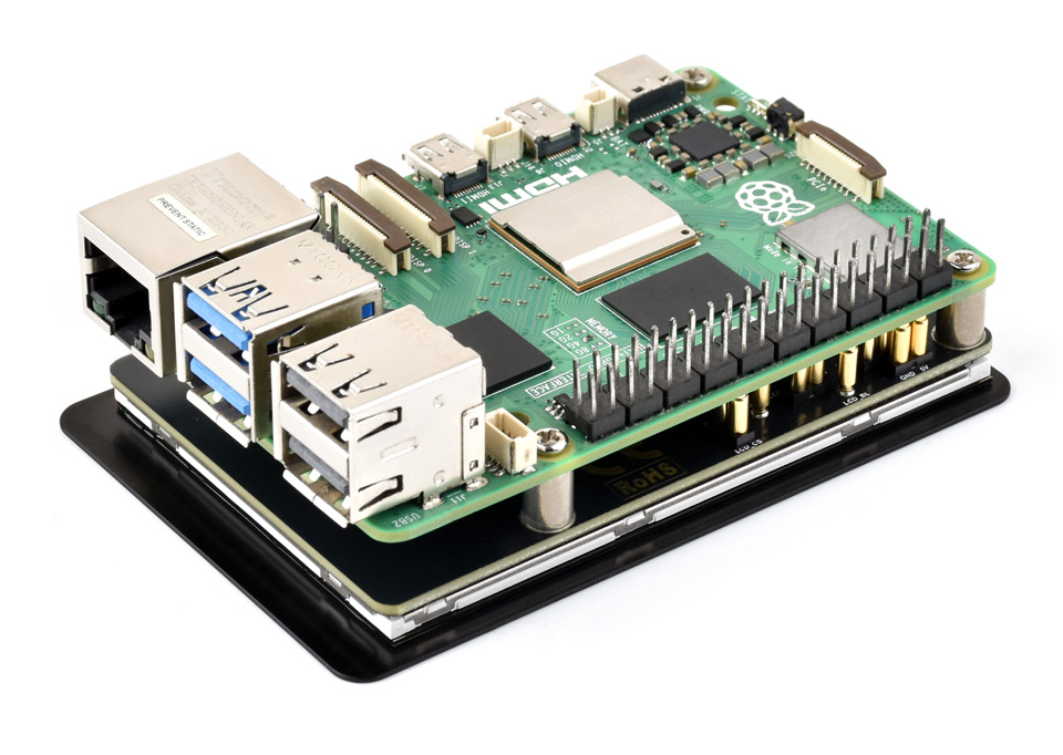
Connecting with Raspberry Pi 5
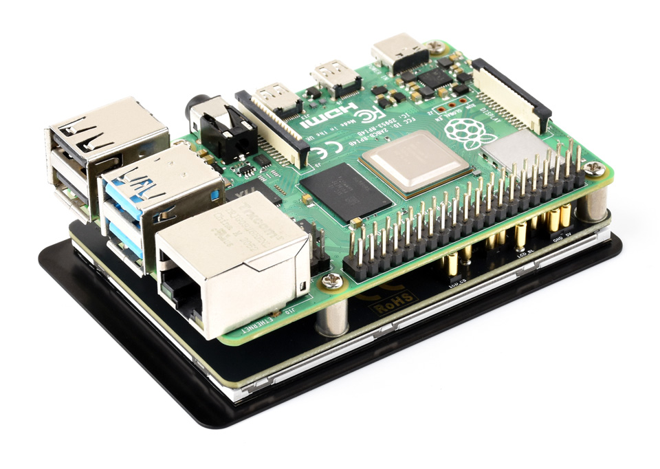
Connecting with Raspberry Pi 4B
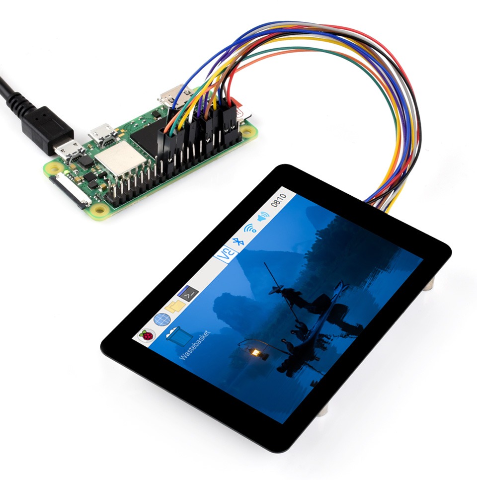
Connecting with Raspberry Pi Zero 2 W
Connecting with ESP32-S3 development board
* for reference only, the Raspberry Pi boards and ESP32-S3 development board are NOT included, please check the Package Content for the detailed part list.

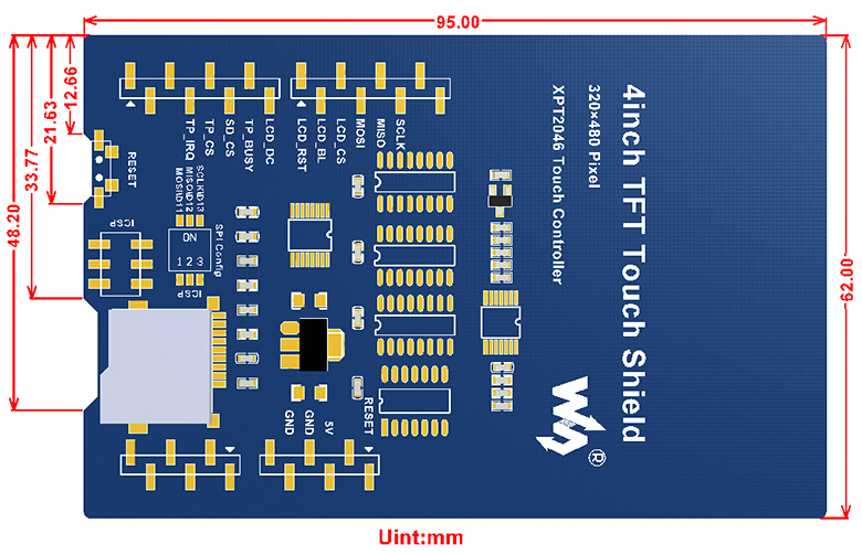
- Resistive touch screen TFT LCD, 4inch, 480x320 resolution
- Standard Arduino interface, compatible with development boards like : Arduino UNO, Leonardo, UNO PLUS, NUCLEO, XNUCLEO
- Onboard stand-alone touch controller, better touching than solutions that use AD pins directly for touch control
- PWM backlight control, allows to adjust the backlight to a comfortable level
- Micro SD slot, provides an easy way to store photos for displaying
- Controlled via SPI, only a few Arduino pins are used
- Comes with STM32 and Arduino examples, convenient for porting
Key Parameters
| LCD Type | TFT |
|---|---|
| LCD Interface | SPI |
| LCD Controller | ILI9486 |
| Touch Screen Type | Resistive |
| Touch Screen Controller | XPT2046 |
| Colours | RGB, 65K colors |
| Resolution | 480x320 (Pixel) |
| Aspect Ratio | 8:5 |
| I/O Voltage | 3.3V/5V |
| Symbol | Arduino / NUCLEO PIN | Description |
|---|---|---|
| 5V | 5V | 5V power input |
| GND | GND | Ground |
| SCLK | D13 | SPI clock |
| MISO | D12 | SPI data input |
| MOSI | D11 | SPI data output |
| LCD_CS | D10 | LCD chip select |
| LCD_BL | D9 | LCD backlight |
| LCD_RST | D8 | LCD reset |
| LCD_DC | D7 | LCD data/command selection |
| TP_BUSY | D6 | Touch panel busy |
| SD_CS | D5 | Micro SD card chip select |
| TP_CS | D4 | Touch panel chip select |
| TP_IRQ | D3 | Touch panel interrupt |
External Dimensions
What's in the box?
1 x 4inch Touch LCD Shield for Arduino
Resources

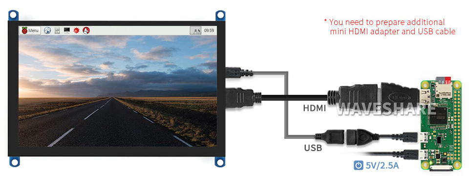
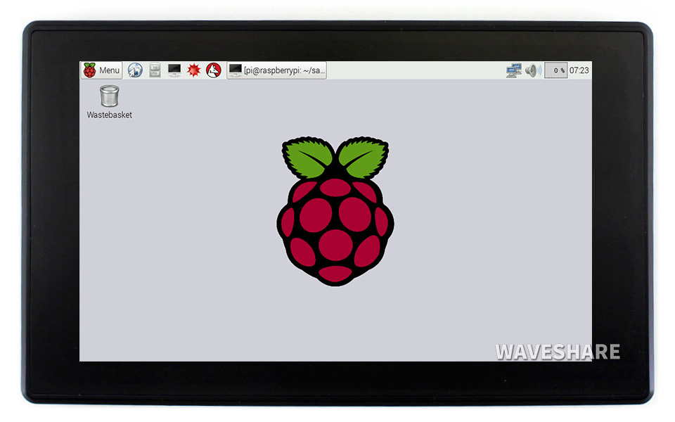
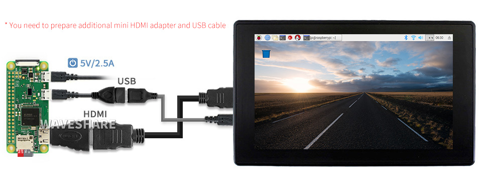
Additional HDMI Cable Required: Raspberry Pi Zero 2 W / Zero W / Zero
Driver Provided: supports Raspbian / Ubuntu / Kali / Retropie
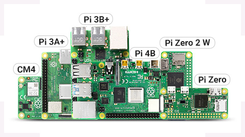
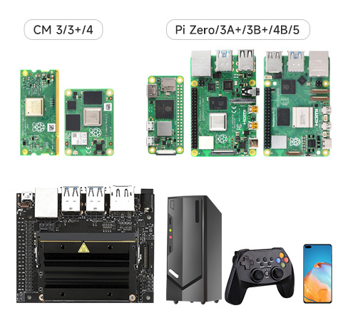
Supports All versions of Raspberry Pi
Working With Raspberry Pi
1 x HDMI cable
1 x HDMI to Micro HDMI Adapter
1 x USB type A plug to micro B plug cable
1 x RPi screws pack (4pcs)
Resources
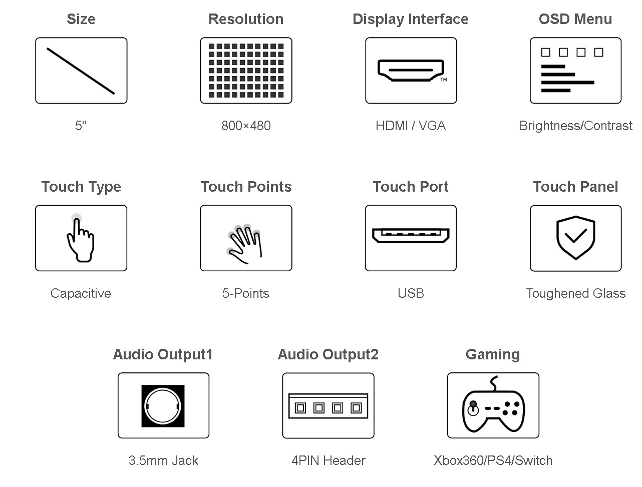
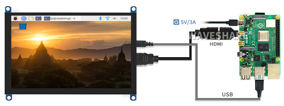
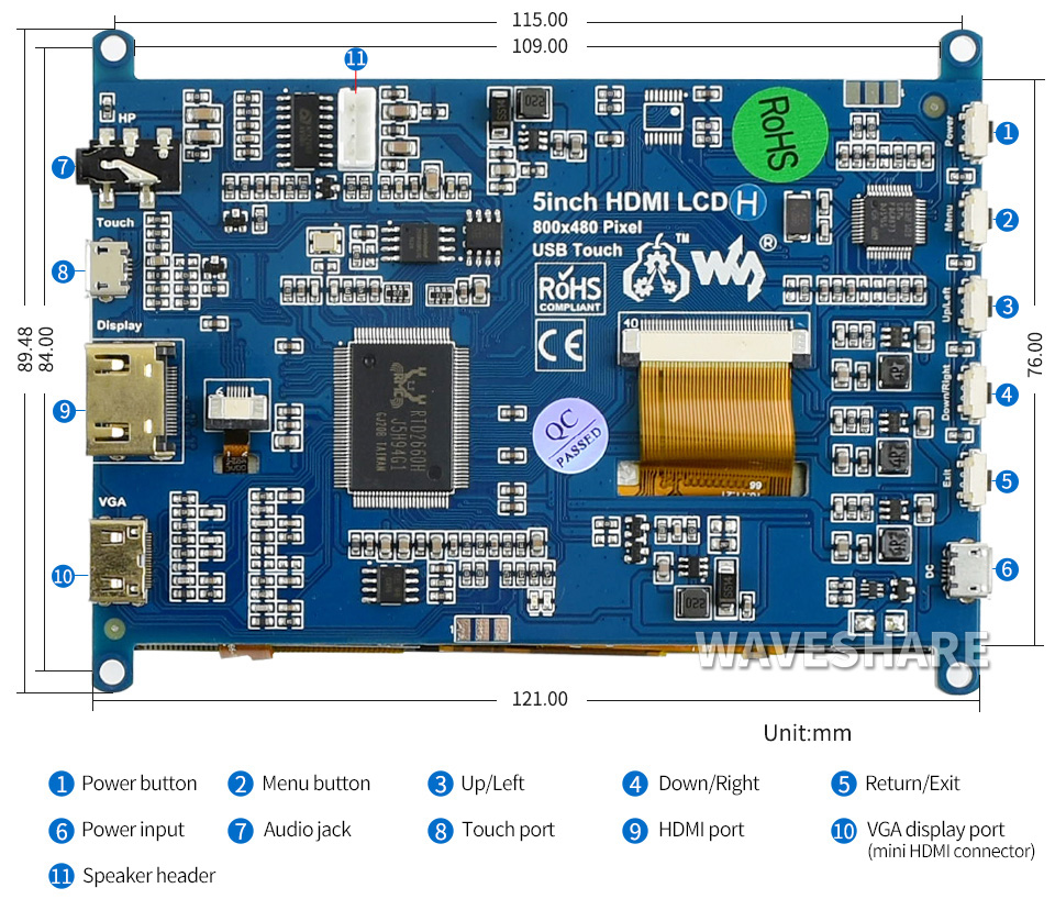
Wiki: 5inch_HDMI_LCD_(H)

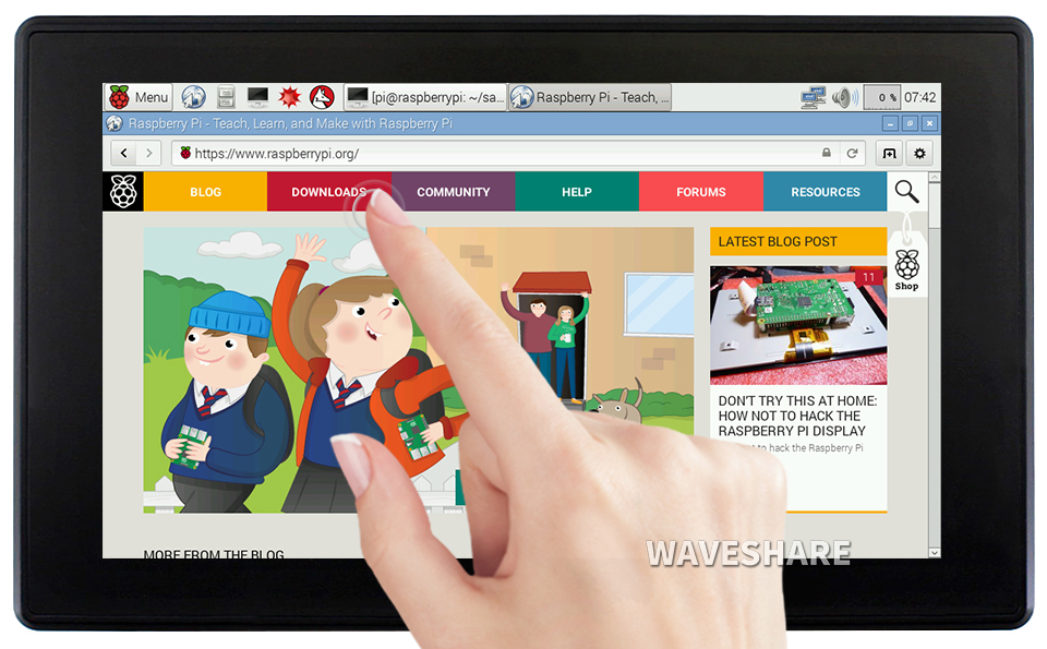
Supports Ubuntu / Kali / WIN10 IoT, single point touch, driver free
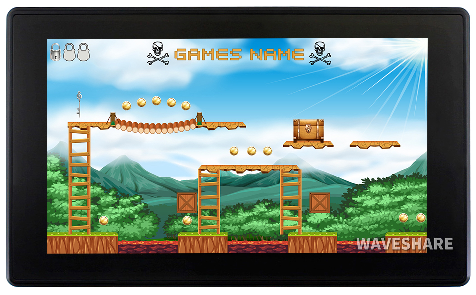
Supports Retropie, driver free
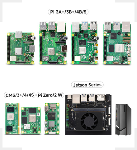
Supports all versions of Raspberry Pi
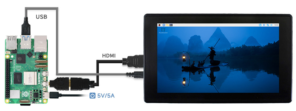
Working with Raspberry Pi 5
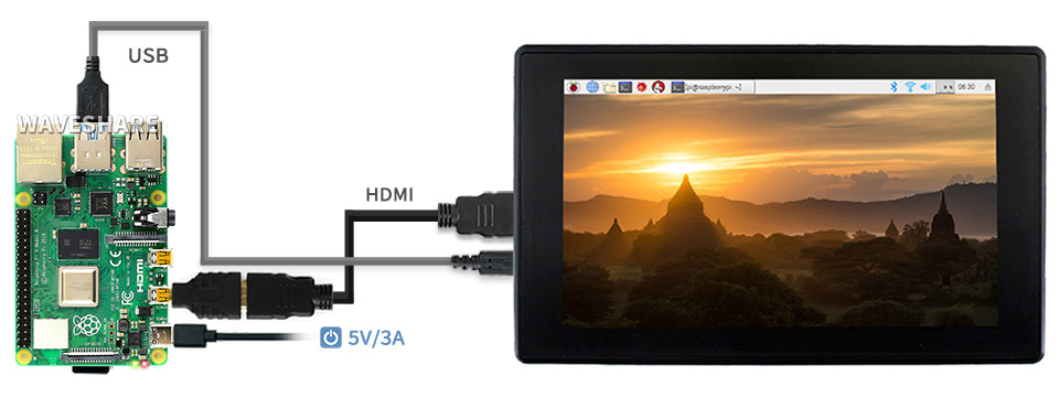
Working with Raspberry Pi 4
Working with Raspberry Pi Zero W
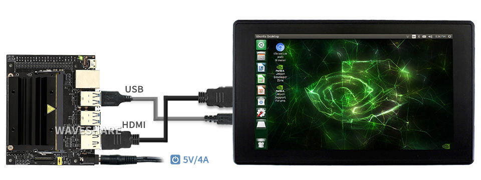
Working with AI Computer Jetson Nano
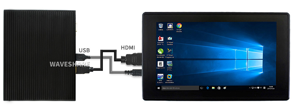
Working with mini PC
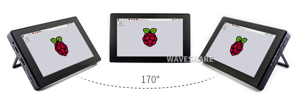
IPS Panel
1) up to 5-point touch, depending on the operating system. 2) up to 6H hardness toughened glass panel.

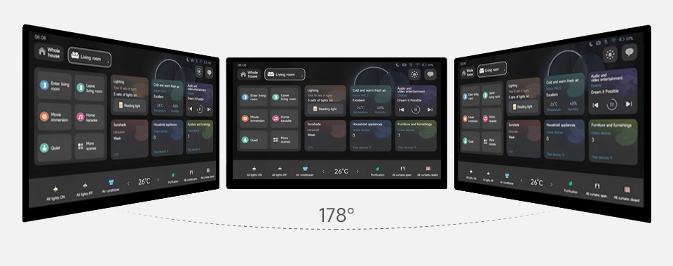
Commercial Quality, Suitable For Commercial IoT Displays, and Smart Home, etc.


Supports Ubuntu / Kali / WIN10 IoT, single point touch, driver free
Supports Retropie, driver free
Supports all versions of Raspberry Pi
Working with Raspberry Pi 5
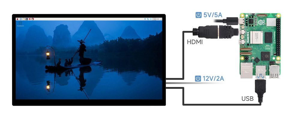
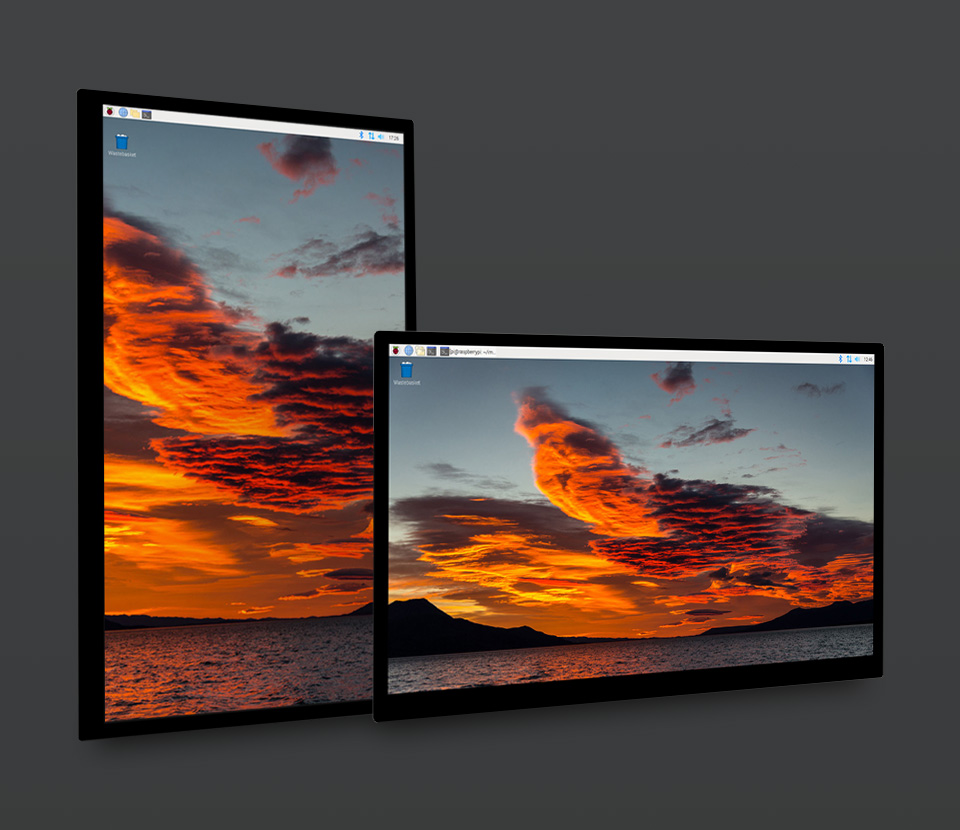
The display orientation is landscape by default, 1920x1080 resolution (H×V).
Change the software config for portrait display
Excellent Display & Color Performance
Wide viewing angle up to 178°, color gamut up to 72% NTSC

- up to 10-point touch, depending on the operating system
- up to 6H hardness toughened glass panel
- Optical bonding, display well and dustproof

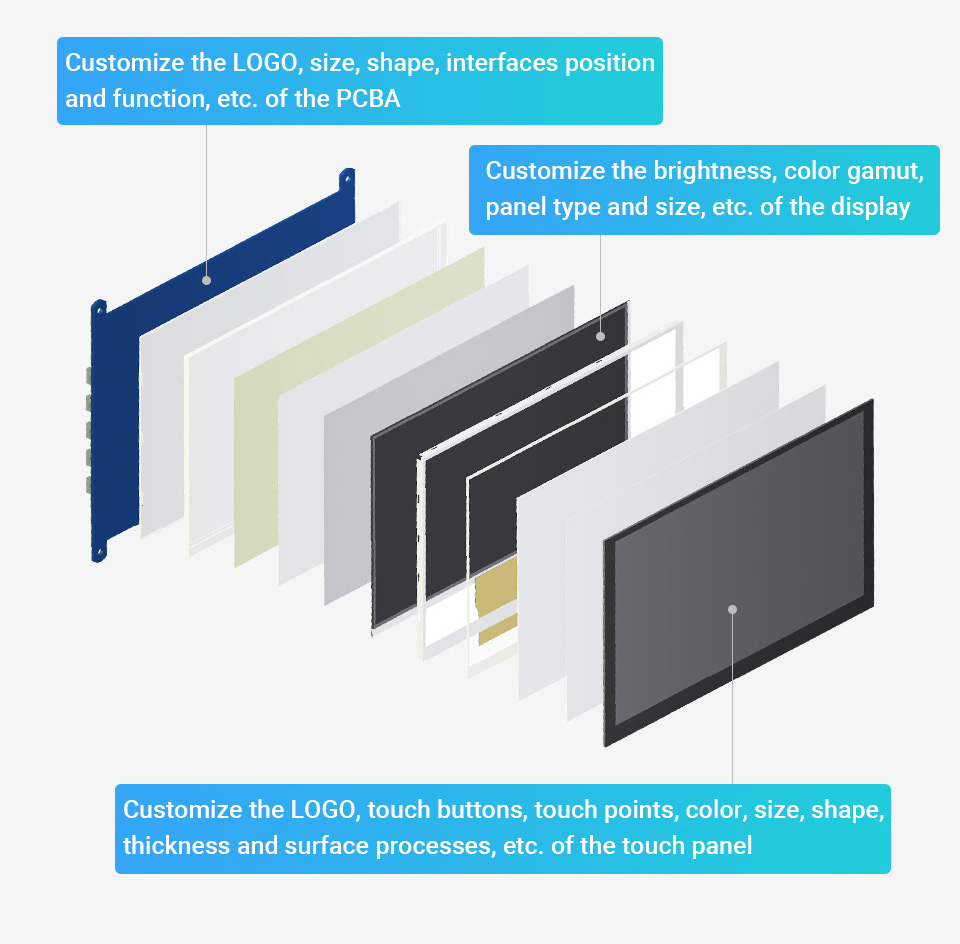
Support the following ways to customize the touch screen display in bulk order
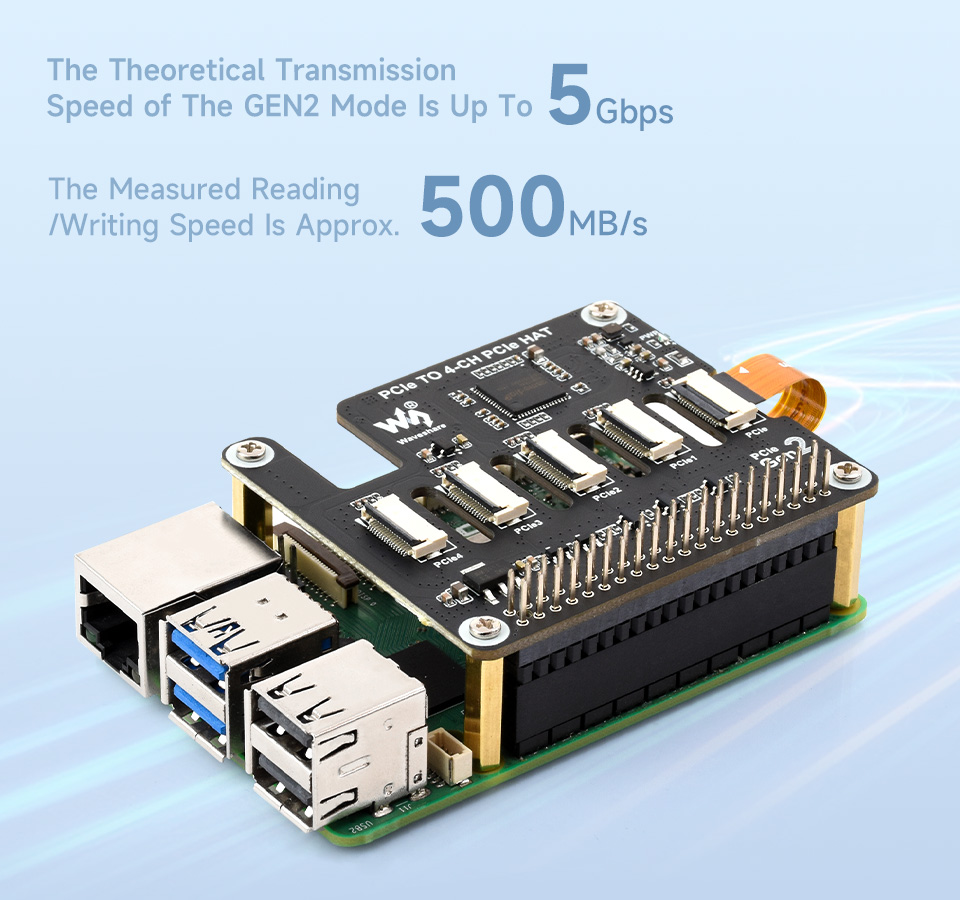
Designed for Raspberry Pi 5
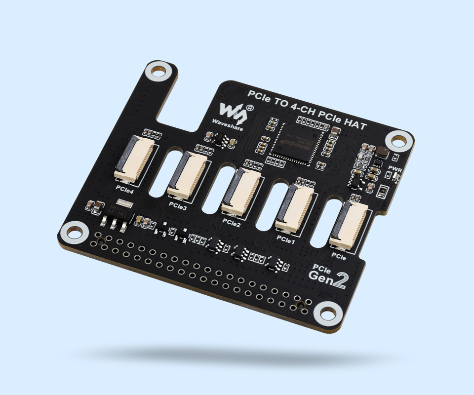
Based on 16PIN PCIe Interface of Raspberry Pi 5
* for reference only, please refer to the Package Content for detailed part list
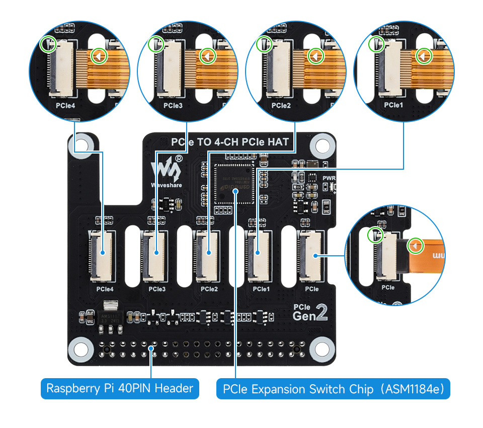
Flexible Combination for Easy Stacking of Multiple PCIe HATs
Expands Multiple PCIe HATs
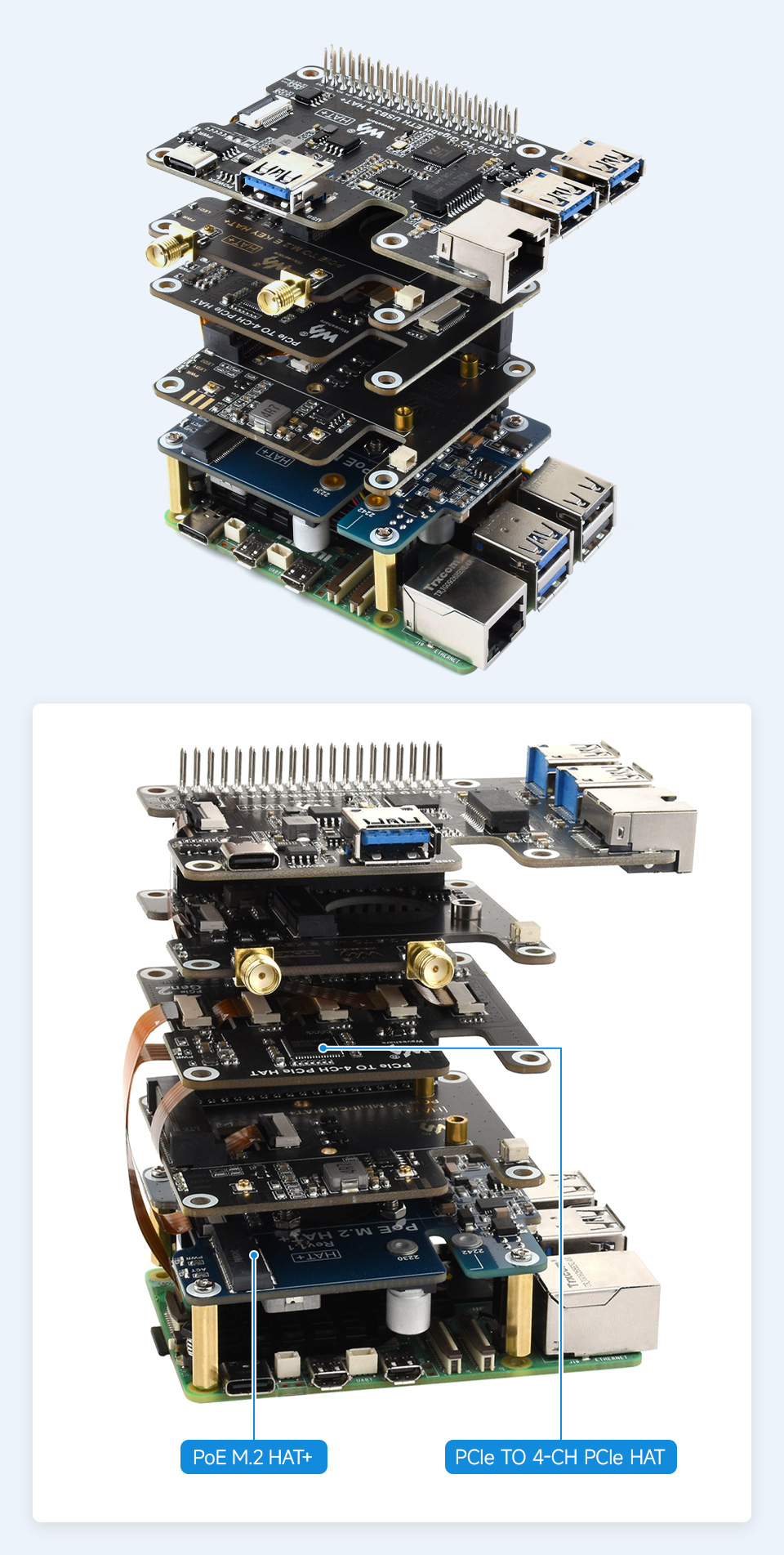
* for reference only, please refer to the Package Content for detailed part list
Supports PCIe Gen2 (PCIe 2.0) Only
1 x PCIe TO 4-Ch PCIe HAT
1 x 2*20 Pin header
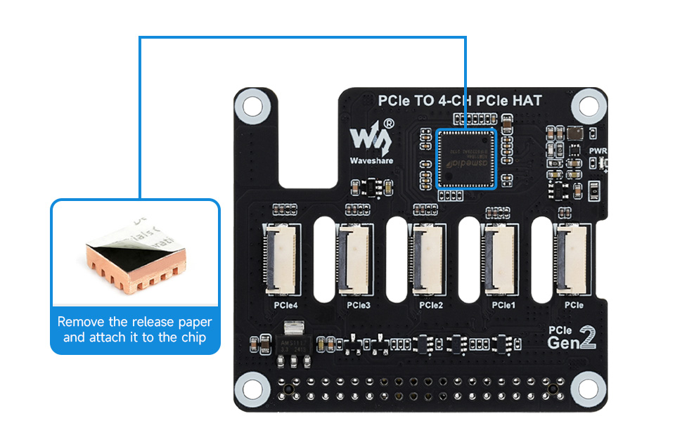
1 x Heatsink
1 x Standoff pack
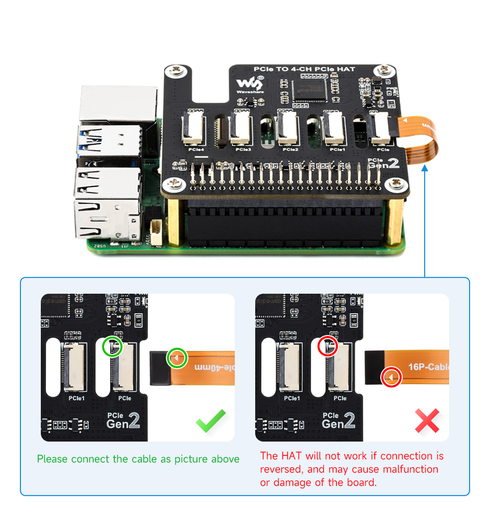
5 x 16P-Cable-40mm
5 x 16P-Cable-70mm

2048 individual RGB LEDs, 4mm pitch
supports Raspberry Pi and Arduino.
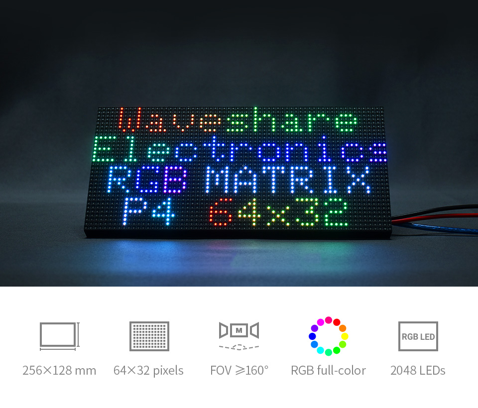
- 2048 individual RGB LEDs, full-color display, adjustable brightness
- 64×32 pixels, 4mm pitch, allows displaying text, colorful image, or animation
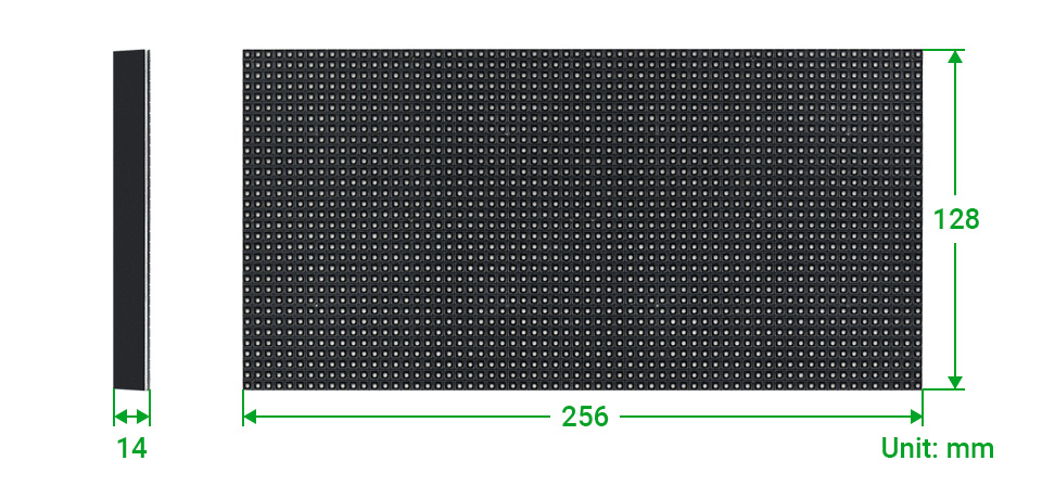
- 256×128mm dimensions, moderate size, suitable for DIY desktop display or wall mount display
- Onboard two HUB75 header, one for controller data input, one for output, chain support
- Provides open source development resources and tutorials, for use with Raspberry Pi, Arduino, and so on
| Dimensions | 256mm × 128mm |
|---|---|
| Pixels | 64×32=2048 DOTS |
| Pitch | 4mm |
| Pixel form | 1R1G1B |
| Viewing angle | ≥160° |
| Control type | synchronization |
| Driving | 1/16 scan |
| Header | HUB75 |
| Power supply | 5V / 4A (VH4 header input) |
| Power | ≤20W |
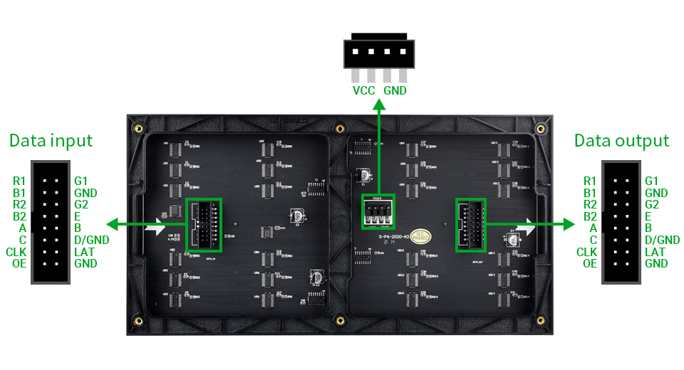
PCB silkscreen and layout may have small differences from batch to batch, but the hardware interface and software are compatible.
| Pin | Description | Pin | Description |
|---|---|---|---|
| VCC | 5V power input | GND | Ground |
| R1 | R higher bit data | R2 | R lower bit data |
| G1 | G higher bit data | G2 | G lower bit data |
| B1 | B higher bit data | B2 | B lower bit data |
| A | A line selection | B | B line selection |
| C | C line selection | D | D line selection |
| E | E line selection | CLK | clock input |
| LAT/STB | latch pin | OE | output enable |
Multi LED matrix panel can be chained together to build a larger panel
via HUB75 input/output header

1 x RGB-Matrix-P4-64x32 LED matrix and accessories
1 x Power supply terminal adapter
1 x 16P wire ~30cm
Features
- Standard Raspberry Pi 40PIN GPIO extension header, supports Raspberry Pi series boards
- I2C controlled, by setting 5 address jumpers, it is stackable up to 32 this modules
- Onboard PCA9685 chip, provides 12-bit hardware PWM to adjust motor speed
- Onboard TB6612FNG dual H-bridge motor driver, high efficiency, low heating
- Integrates 5V regulator, up to 3A output current, can be powered from battery through VIN terminal
- Reserved I2C control pins, allows to work with other control boards
- Comes with development resources and manual (examples in BCM2835, wiringPi, and python)
Specifications
- Power supply: 6V~12V (VIN terminal)
- Logic voltage: 3.3V
- PWM driver: PCA9685
- Control interface: I2C
- Motor driver: TB6612FNG
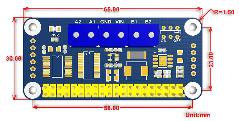
- Dimension: 65mm x 30mm
- Mounting hole size: 3.0mm
Dimensions
What's in the box?
1 x Motor driver HAT
Resources
Specifications
| Transmission standard | HDMI1.4B |
|---|---|
| Video input | 1080p/1080i/720p/576p/576i/480p/480i |
| Signal transmission | Supports using CAT-5E/6 network cable (CAT-6 recommended) instead of HDMI cable, the distance between transmitter and receiver up to 50m |
| Power input | Type-C port (DC 5V 1A) |
| Applicable scenarios | Security monitoring, Video conference, Multimedia teaching, Home theater, etc. |
Connection Example
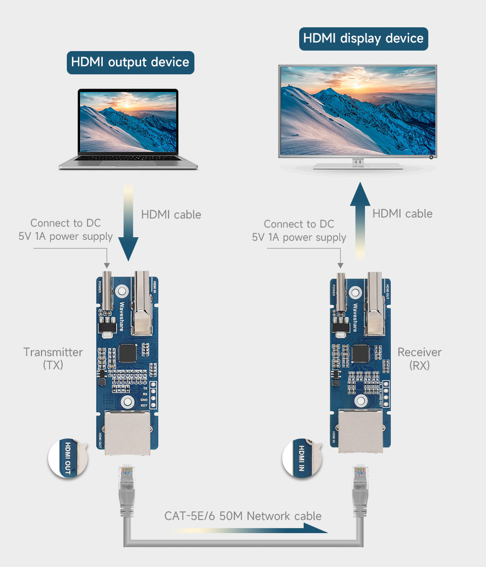
Note: The quality of the network cable will affect the signal transmission quality, it is recommended to use CAT-6 network cable for better transmission.
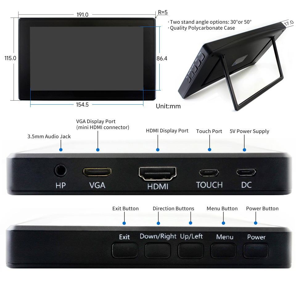
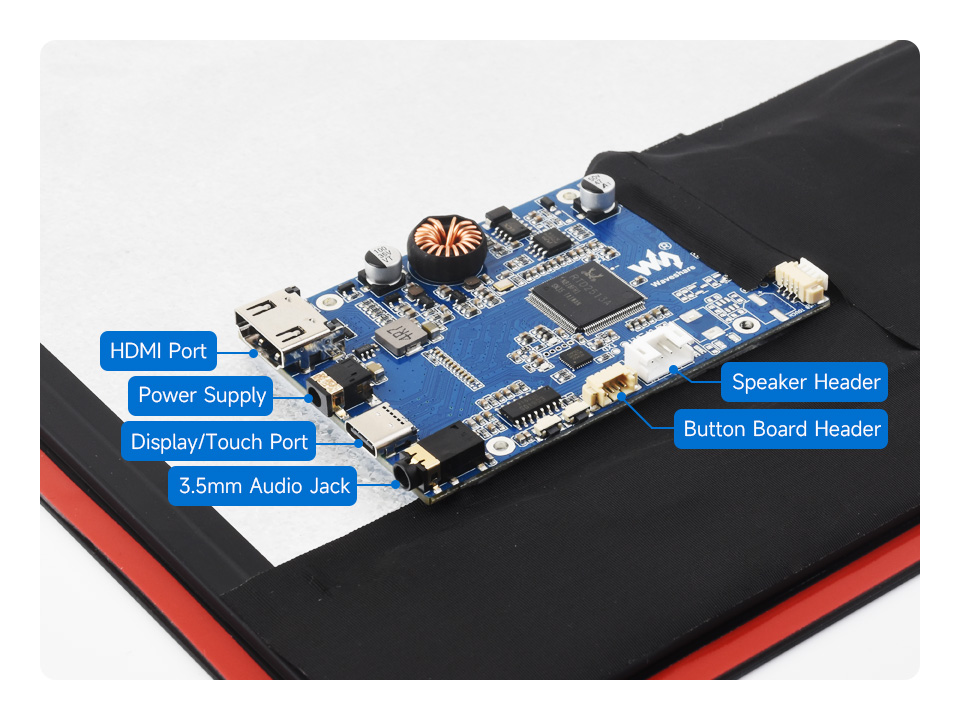
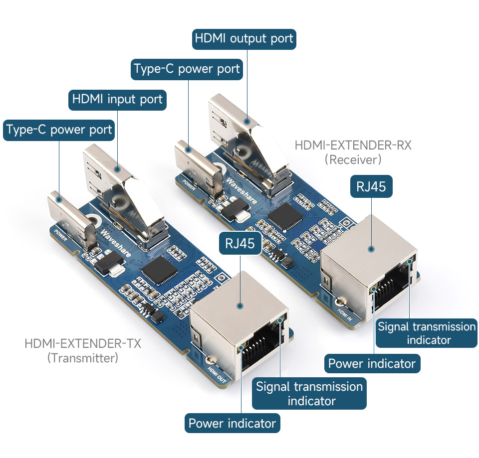
Onboard Interface
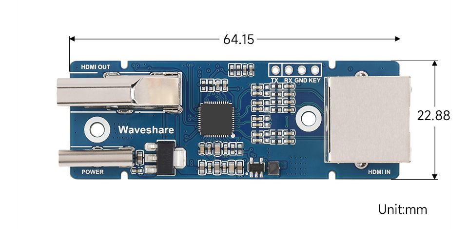
Outline dimensions
What's in the box?
1 x HDMI-EXTENDER Sender
1 x HDMI-EXTENDER Receiver
You will also need 2 x USB_C power supplies and Cat5e/6 cable
Resources

240 MHz Xtensa 32-bit LX7 Dual-core Processor


The ESP32-S3-RGB-Matrix is a high-performance, highly integrated LED matrix panel driver board designed by Waveshare. It is suitable for HUB75 interface RGB matrix panels and related embedded applications. Based on the ESP32-S3 microcontroller, it integrates large-capacity Flash storage, RTC chip, IMU, TF card slot, low-power audio codec chip, dual microphones, and so on. It also provides reserved interfaces such as USB, UART, I2C, and GPIO, offering strong scalability and enabling users to quickly develop and integrate it into practical applications.
- Equipped with ESP32-S3-N32R16 Xtensa 32-bit LX7 dual-core processor, up to 240MHz main frequency
- Supports 2.4GHz Wi-Fi (802.11 b/g/n) and Bluetooth 5 (LE)
- Built in 512KB Static RAM and 384KB ROM, with onboard 32MB Flash memory and 16MB PSRAM
- Compatible with the full product line of Waveshare LED RGB matrix panels, and can smoothly run graphical interface programs such as LVGL
- Onboard ES7210 echo cancellation chip for improved voice processing performance
- Onboard ES8311 low-power audio codec chip, supporting high-quality audio input and output
- Equipped with dual microphones array for audio algorithms such as noise reduction and echo cancellation, suitable for accurate speech recognition and voice wake-up applications
- Onboard speaker header, supports audio playback output, and can be connected directly to a speaker
- Onboard QMI8658 6-axis IMU (3-axis accelerometer and 3-axis gyroscope) for detecting motion gesture, etc.
- Integrated SHTC3 temperature and humidity sensor for accurate environmental monitoring
- Onboard TF card slot for extended storage of images, audio, and various file types, making it convenient for reading and writing data
- Onboard PCF85063 RTC chip with a reserved SH1.0 batt connector, enabling continuous timekeeping during power loss
- Reserved GPIO expansion header for peripheral expansion and custom function development, supporting diverse application requirements
- Dual power supply ports design, supporting stable operation of up to six 64 × 64 RGB Matrix panels, with cascading support for large-scale display applications
- Onboard USB Type-C port for power supply, firmware programming, and debugging
- Onboard RST and BOOT programmable buttons for easy custom function development
| Power Voltage | 5V |
|---|---|
| Maximum Current Rating | 10A |
| Supported Resolution | 64 × 64, 64 × 32, 80 × 40, 96 × 48 |
| Interface Type | HUB75 |
| Maximum Resolution (Cascaded) | 6 × 64 × 64 |
| Operating Temperature | -40℃ ~ +85℃ |
| Dimensions | 50 × 42 (mm) |
Powered by Xtensa 32-bit LX7 dual-core processor with frequency up to 240 MHz
Powerful AI Computing Capability & Reliable security features


No complicated assembly or wiring required—quickly integrate with AI models

Comprehensive SDK, dev resources, tutorials to help you easily get started


- for reference only, please refer to the package content for the detailed part list.

* for reference only, please refer to the package content for the detailed part list.

- ESP32-S3-N32R16
The SoC with WiFi and Bluetooth, up to 240MHz operating frequency - QMI8658
QST 6-axis sensor (3-axis accelerometer, 3-axis gyroscope) - RTC batt connector
SH1.0 female header - SHTC3
High-precision temperature and humidity sensor - Type-C power supply port
- USB Type-C port
Supports power supply, program download, and debugging - TF card slot
Supports external TF card
- Speaker header
- Dual microphones
- 5V power output
power supply output for LED matrix panels - BOOT button
- RESET button
- GPIO expansion header
for peripheral expansion and customization - SN74HC245
Octal bus transceiver with 3-State outputs - ES8311
Low-power mono audio codec chip - ES7210
Audio decoder IC


Overview
This is a small 1D/2D codes reader, by using the intelligent image recognition algorithm, it will decode the barcode or 2D code on paper or screen, fast and accurately.
Through the onboard USB and UART interface, it can be directly plugged into a computer, or be easily integrated to kinds of devices due to its small form factor.
Features
- Easy to use, requires no knowledge of image recognition
- Decodes various common 1D/2D codes such as Barcode, QR code etc.
- Onboard micro USB and UART serial port, allows to connect with computers or embedded devices
- Configurable via scanning 'configuration code'
- Onboard light source, works in the dark
Specifications
- Operating voltage: 5V
- Operating current: 135mA (scanning), 58mA (standby), 2mA (sleep)
- Operating temperature: 0°C~60°C
- Operating humidity: 5%~95% (Non-condensing)
- Communication interface: UART, USB
- Decodes 1D codes: Codebar, Code 11, Code 39/Code 93, UPC/EAN, Code 128/EAN128, Interleaved 2 of 5, Matrix 2 of 5, MSI Code, Industrial 2 of 5, GS1 Databar(RSS)
- Decodes 2D codes: QR code, Data Matrix, PDF417
- DOES NOT SUPPORT THE FORMAT FOR SCANNING RSA DRIVER'S LICENSE
- Light source: white
- Scan angels: roll 360°, skew ±65°, pitch ±60°
- Field of view: 28° (horizontal), 21.5° (vertical)
- Dimension: 53.3mm x 21.4mm
What's in the box?
1 x WS Barcode Scanner Module
Resources

This neat little 4 port USB hub pHAT for the Raspberry Pi B+/2/3 & Raspberry Pi Zero/W, provides 4 extra USB ports for your Pi and features a USB to UART converter for easy serial communication!
The board comes in a pHAT format and comes complete with micro USB cable, and Micro USB/Micro USB shim PCB. Raspberry Pi 3, Zero and dongle not included.
Features
- 4 USB Ports, compatible with USB2.0/1.1
- Onboard USB to UART, convenient for Raspberry Pi serial debugging
- Onboard multi indicators, for monitoring the status of power, USB to UART, and each USB port
- Operating voltage: 5V
- Dimension: 65mm × 30mm
- Mounting hole size: 3.0mm
Assembly Instructions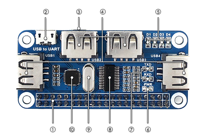
- Raspberry Pi GPIO interface: for connecting Raspberry Pi
- USB to UART: for controlling the Raspberry Pi via serial terminal
- USB HUB interface (Micro USB): for connecting the HUB to the Raspberry Pi USB port
- Raspberry Pi Zero / Zero W: connected via Micro USB to Micro USB PCB
- Raspberry Pi B+ / 2B / 3B: connected via USB to Micro USB cable
- USB extended ports: USB1~USB4
- USB port indicators: dedicated indicator for each USB port, D1~D4 for USB1~USB4 respectively
- Power indicator
- USB to UART indicator
- FE1.1S: USB HUB chip
- 12MHz crystal
- CP2102: USB to UART converter
What's in the box?
1 x USB HUB HAT
1 x Micro USB connector
1 x Micro USB cable
1 x RPi screws pack (2pcs)
Resources

Features at a glance
- Original FT232RL onboard
- Supports Mac OS, Linux, Android, WinCE, Windows 7/8/8.1/10/11...
- 3x VCCIO power mode via jumper setting:
- - VCCIO - 5V: 5V output
- - VCCIO - 3.3V: 3.3V output
- - open the jumper: powered from target board (3.3V-5V)
- 3x LED indicators: TXD, RXD, PWR
- Pins accessible on pinheaders: TXD, RXD, RTS#, CTS#
- Other pins are accessible on drilled holes, easily connected to user application system (the pin pitch is compatible with universal prototype board)
FT232 solution
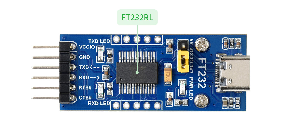
- VCCIO ↔ 3.3V or 5V output (the module is powered from USB, and the onboard jumper should be shorted to 3.3V or 5V)
- GND ↔ GND
- TXD ↔ MCU.RX (signal direction: MCU.RX << FT232 << PC.TX)
- RXD ↔ MCU.TX (signal direction: MCU.TX >> FT232 >> PC.RX)
- RTS ↔ MCU.CTS (signal direction: MCU.CTS << FT232 << PC.RTS)
- CTS ↔ MCU.RTS (signal direction: MCU.RTS >> FT232 >> PC.CTS)
Outline Dimensions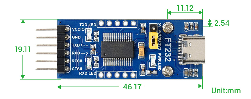

Supports Charging And Power Output At The Same Time, With Dynamic Path Management, Stable 5V Output
Comes with online development resources and manual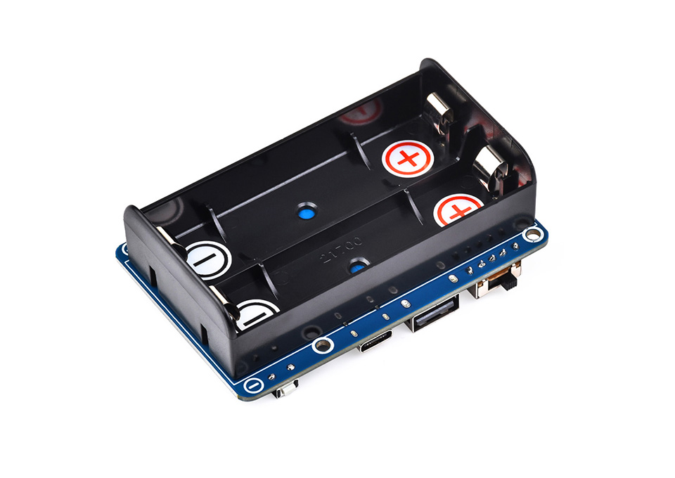
The UPS HAT (D) is an uninterruptible power supply (UPS) expansion board specially designed for the Raspberry Pi series. Onboard switching Li battery charging chip with path management, boost converter chip, and voltage/current monitoring chip which can monitor the operating state of the batteries via the I2C interface.
- Adopts pogo pins connector design, compatible with Raspberry Pi 3 / 3B+ / 4B, etc.
- Onboard Li battery charging chip, with dynamic path management, more stable power supply
- Onboard boost converter chip for stable 5V power output
- I2C bus communication, monitoring the batteries voltage, current, power, and remaining capacity in real time
- Multi battery protection circuits: over charge/discharge protection, over current protection, short circuit protection, more safe and stable
- Onboard MCU management, supports detecting power connection and booting the Raspberry Pi
- Supports displaying battery level on the system, easy to check the battery remaining capacity
- Onboard LED indicators for monitoring the battery operating status
- Comes with online development resources and manual
| OUTPUT VOLTAGE | 5V |
|---|---|
| CONTROL BUS | I2C |
| BATTERY SUPPORT | 21700 Li battery × 2 (in parallel, NOT included) |
| CHARGER SUPPORT | 5V (Type-C port) |
| DIMENSIONS | 56 × 85mm |
| MOUNTING HOLE SIZE | 3.0mm |
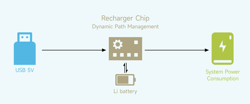
- When connected to the external power supply, the system will be powered and the battery will be charged at the same time, and the battery will be disconnected after being fully charged to avoid battery life damaging caused by frequent charging and discharging
- When the external power supply is insufficient, the battery will provide power output together with the external power supply at the same time to ensure system normal operation
- When the external power supply is connected, the system will keep running normally even when the battery fails or is taken out. And automatically switch over to batteries output if the external power supply is unavailable, keeps the system running without any trouble
Longer Battery Life
Onboard Warning Indicators, Easy To Check If The Battery Is Connected Correctly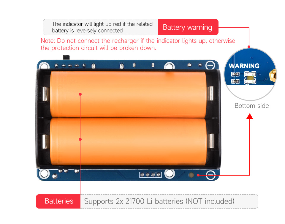
Powering The Raspberry Pi Via Pogo Pins, Without Using Any GPIO Resource,
Compatible With Raspberry Pi 3 / 3B+ / 4B, Etc.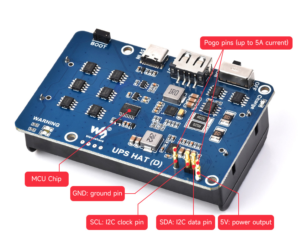
Monitoring The Batteries Voltage, Current, Power, And Remaining Capacity Via I2C
When the voltage dips too low, it is possible to save files properly and then shut down the system by software, to avoid any data loss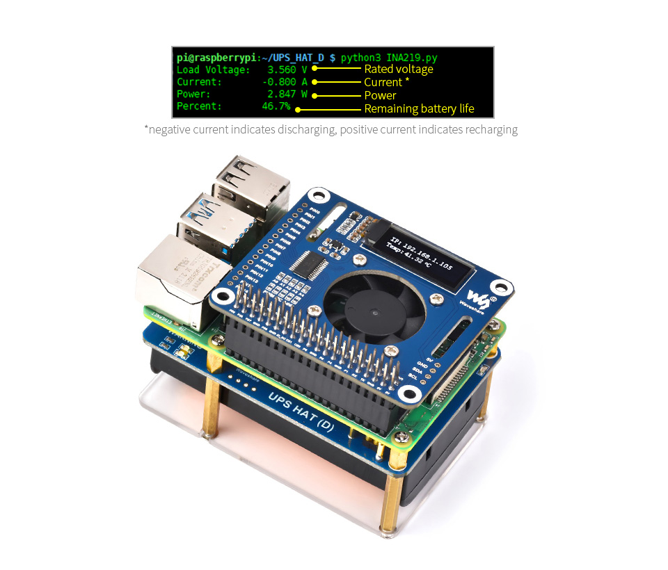
Detecting Power Connection
Easy To Check The Battery Status In Real-Time, And Automatically Shutdown When The Battery Level Is Low. Onboard MCU Chip For Detecting Power Connection And Automatically Rebooting The Raspberry Pi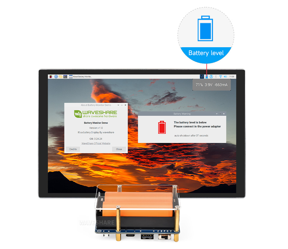
Outline Dimensions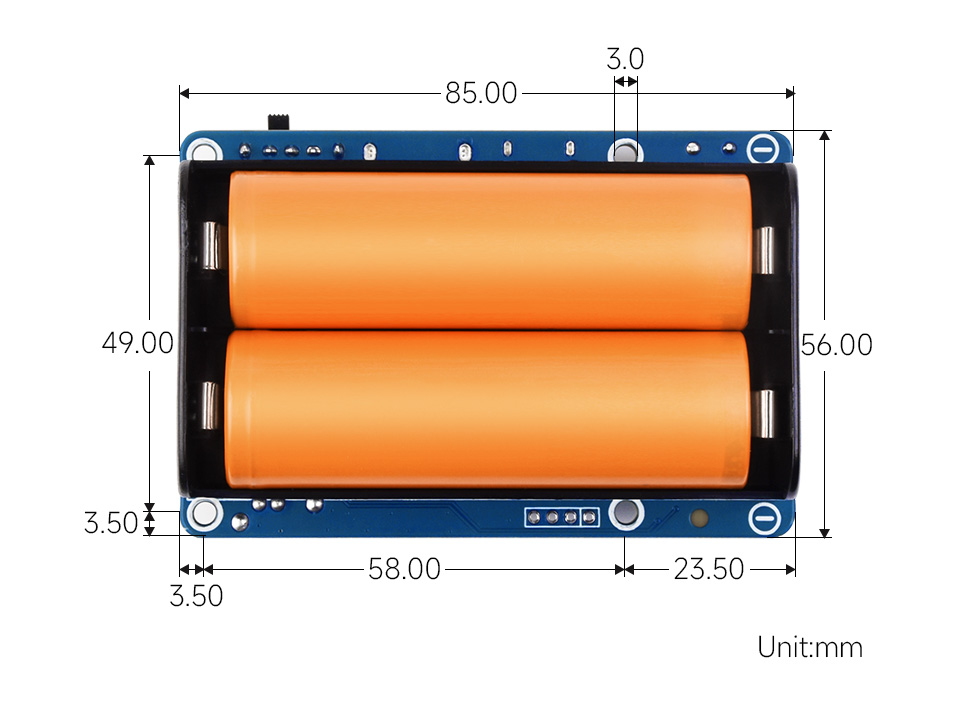
What's in the box?
1 x UPS HAT (D)
1 x Acrylic protection panel
1 x Screws pack
You might need to grab some 21700 batteries
Resources
Wiki: http://www.waveshare.com/wiki/UPS_HAT_(D)

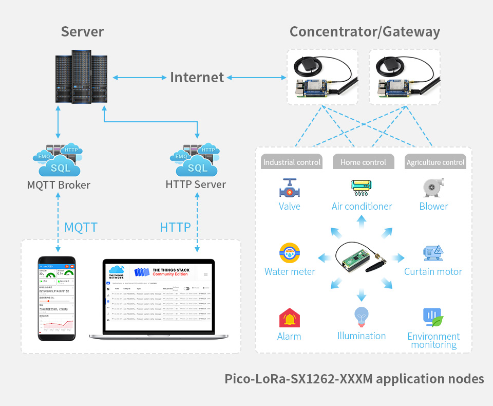
LoRaWAN Protocol Support
Features At A Glance
The Pico-LoRa-SX1262-XXXM is LoRa node expansion module designed for Raspberry Pi Pico based on SX1262 with better performance than the SX127X series. The LoRa modulation technology solves the balancing problem between transmission distance, interference immunity, and power consumption that traditional solutions aren't able to deal with.
It supports LoRaWAN protocol, which allows it to connect the TTN, ChirpStack servers through a LoRa gateway to use LoRa Cloud service fast and easily.
- Standard Raspberry Pi Pico header, supports Raspberry Pi Pico series boards
- Supports LoRaWAN protocol, different frequency bands are available
- Adopts active temperature compensation crystal oscillator, ensuring stable long-term operating in extreme high/low temperature conditions
- Supports FSK, GFSK, LoRa modulations, outstanding anti-blocking performance and ultra long communication distance
- PH1.25 battery header and recharge controller, allows connecting rechargeable Lithium battery
- High receiving sensitivity (up to -148dBm), programmable emitting power (up to 22dBm)
- Supports preamble detection, with CRC, up to 256 bytes data packet engine
- Comes with development resources and manual (example in C)
Specifications
| FREQUENCY BAND | 868M (863~870MHZ) | ||
|---|---|---|---|
| RFID | SX1262 | ||
| Emiting power | 22dBm | ||
| Emiting current | 107mA@22dBm | 118mA@22dBm | |
| Receiving current | 5.3mA@125KHz | ||
| Modulation | LoRa/(G)FSK | ||
| Operating voltage | 3.3V | ||
| Communication bus | SPI | ||
| Operating temperature | -40 ~ 85℃ | ||
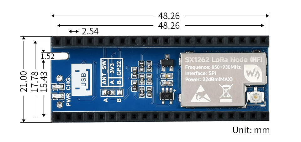
| Dimensions | 21.00 × 52.00mm | ||
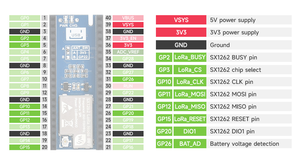
Raspberry Pi Pico Header Compatibility
Onboard Female Pin Header For Direct Attaching To Raspberry Pi Pico
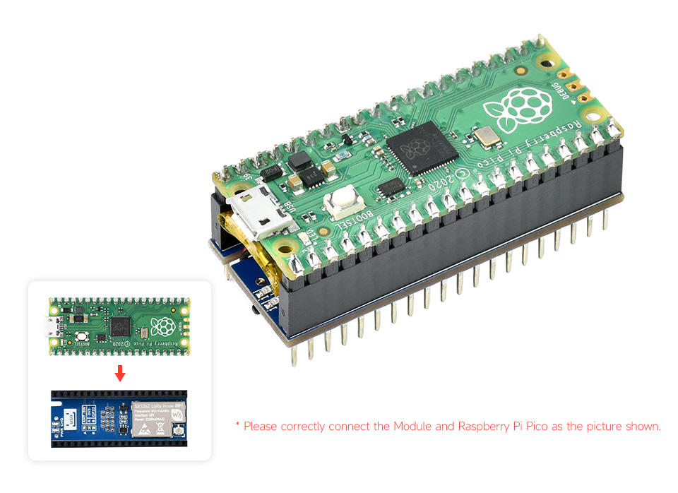
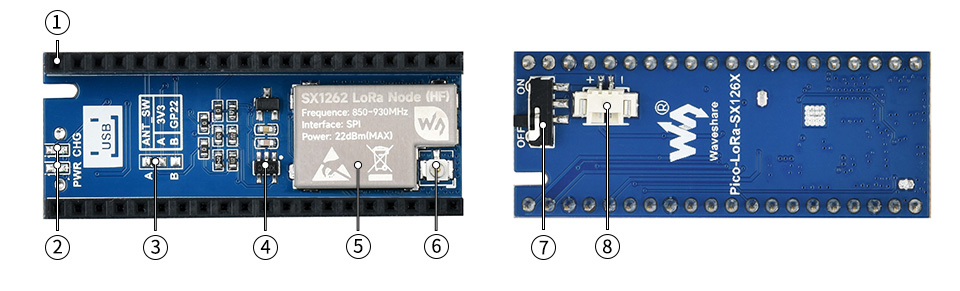
- Raspberry Pi Pico header
- Status indicators
PWR: power indicator
CHG: recharge indicator - RF switch control
A: controlled by high level
B: controlled by GPIO22
- MCP73831 recharge IC
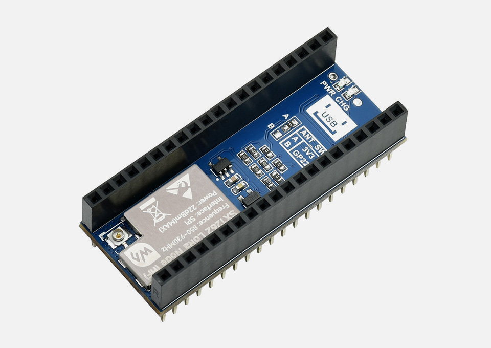
- SX1262 module
- IPEX 1 antenna connector
- Power switch
- PH1.25 battery header
Pinout Definition
Industrial Control, Intelligent Home, And Data Acquisition...
Outline Dimensions
What's in the box?
1 x Pico-LoRa-SX1262-XXXM
1 x 3.7V 600mAh Li-po battery
1 x Antenna 2DB
1 x IPEX1 to SMA wire
Resources
Wiki: Pico-LoRa-SX1262

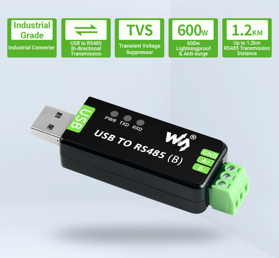
Features At A Glance
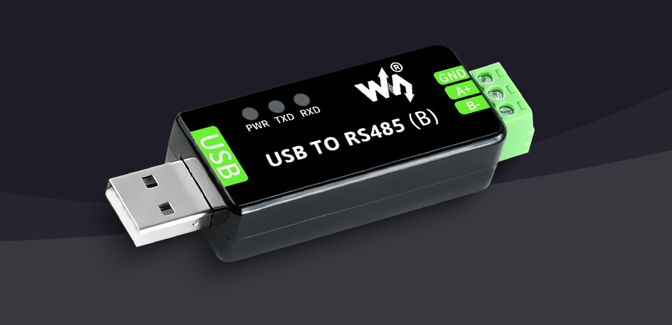
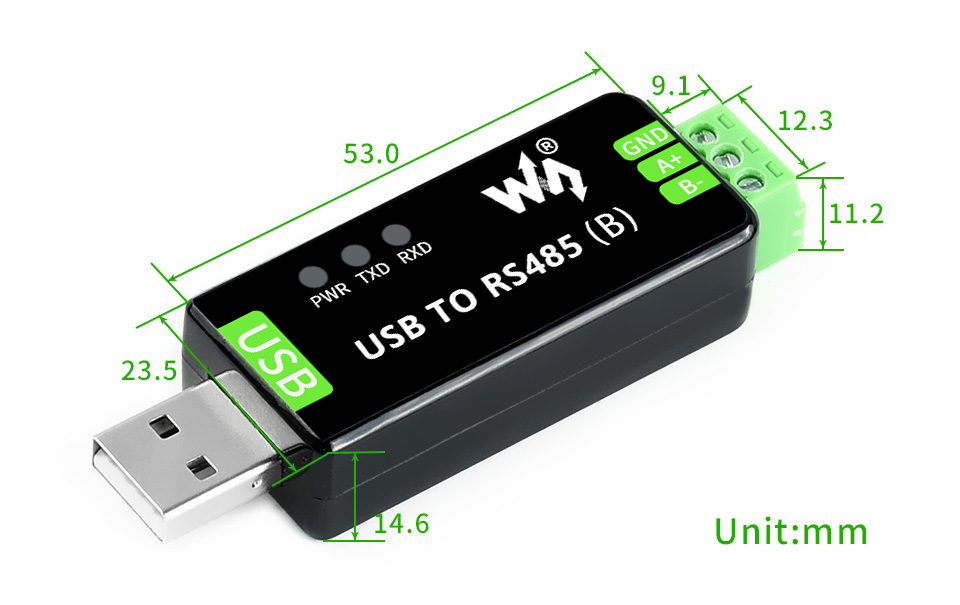
- Support USB to RS485 bidirectional conversion
- Fast communication, stable and reliable, better compatibility
- Onboard TVS (Transient Voltage Suppressor), effectively suppress surge voltage and transient spike voltage in the circuit, lightning proof & anti-electrostatic
- Onboard resettable fuse and protection diodes, ensures the current/voltage stable outputs, provides over-current/over-voltage proof, improves shock proof performance
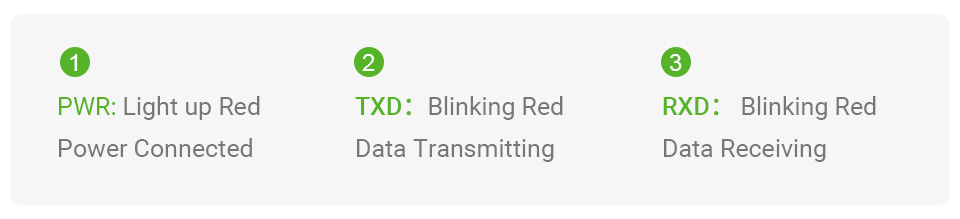
- 3 LEDs for indicating the power and transceiver status
Specifications
| PRODUCT TYPE | Industrial Grade USB to RS485 converter | |
|---|---|---|
| HOST PORT | USB | |
| DEVICE PORT | RS485 | |
| BAUDRATE | 300bps ~ 3Mbps | |
| USB | Operating voltage | 5V |
| Connector | USB-A | |
| Protection | 200mA self-recovery fuse, ESD protection | |
| Transmission distance | About 5m | |
| RS485 | Connector | Screw terminal |
| Pins | A+, B-, GND | |
| Direction control | Hardware automatic control | |
| Protection | 600W lightningproof and surge-suppress, 15KV ESD protection (onboard 120R balancing resistor) | |
| Transmission distance | About 1.2km(low rate) | |
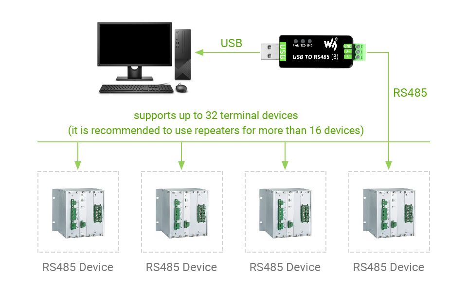
| Transmission mode | Point-to-multipoints (up to 32 nodes, it is recommended to use repeaters for 16 nodes or more) | |
| LED INDICATORS | PWR | Red power indicator, light up when there is USB connection and voltage is detected |
| TXD | Red TX indicator, light up when the USB port sends data | |
| RXD | Red RX indicator, light up when the device ports send data back | |
| OPERATING ENVIRONMENT | Temperature | -15℃ ~ 70℃ |
| Humidity | 5%RH ~ 95%RH | |
| OPERATING SYSTEM | Mac, Linux, Android, WinCE, Windows 11 / 10 / 8.1 / 8 / 7 | |
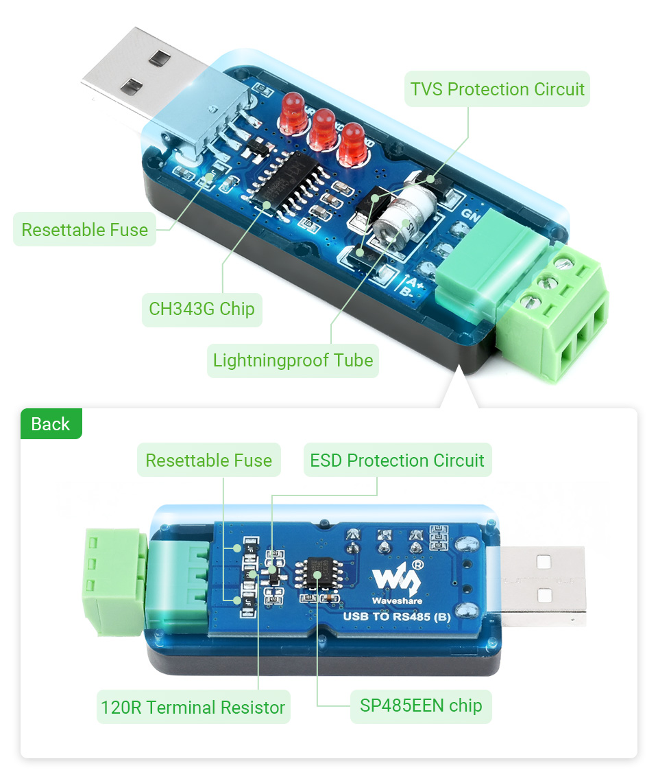
Onboard Original CH343G And SP485EEN Chips, Providing Better Stability And Compatibility, Built-In Lightningproof Tube, Resettable Fuse, ESD And TVS Protection Circuits, Etc.
The USB Signal Can Be Converted Into A Balanced Differential RS485 Signal And The Transmission Rate Is Stable. The Reliable Speed Is 300bps ~ 3Mbps, The Transmission Distance Is About 1.2km For RS485, And About 5 Meters For USB.
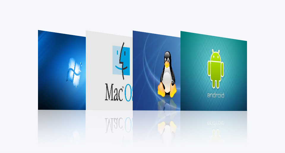
Supports Mac, Linux, Android, WinCE, Win11/10/8.1/8/7/XP, Etc.
Onboard 3 LEDs For Indicating The Power And Transceiver Status
What's in the box?
1 x USB TO RS485 Bidirectional Converter
Resources
www.waveshare.com/wiki/USB_TO_RS485_(B)

Power Your Pi Zero Seamlessly From Power Connection OR The Backup Batteries
Supports Recharging And Regulated 5V Output At The Same Time, I2C Monitoring
SAFETY CAUTIONS
- Li-ion and Li-po batteries are quite unstable. They may cause fire, personal injury, or property damage, if they're not properly recharged or used.
- Do not reversely connect the polarities when recharging or discharging the battery. Do not use inferior charger/charging panel to recharge the battery.
- Do not mix use old batteries with new ones, avoid using batteries of different brands.
- When buying Lithium battery, should always make sure the battery specification is compatible with the expansion board. Choose batteries from formal manufacturer, and ensure the batteries will work stably and safely by aging test.
- Lithium batteries have limited cycle life, they will also deteriorate as time goes by. Should be replaced with new ones when the batteries reaching their max cycle life, or working over two years, whichever comes first.
- Should be placed carefully and properly, keep it away from inflammables and explosives articles, away from children, avoid any safety accident caused by careless storage.
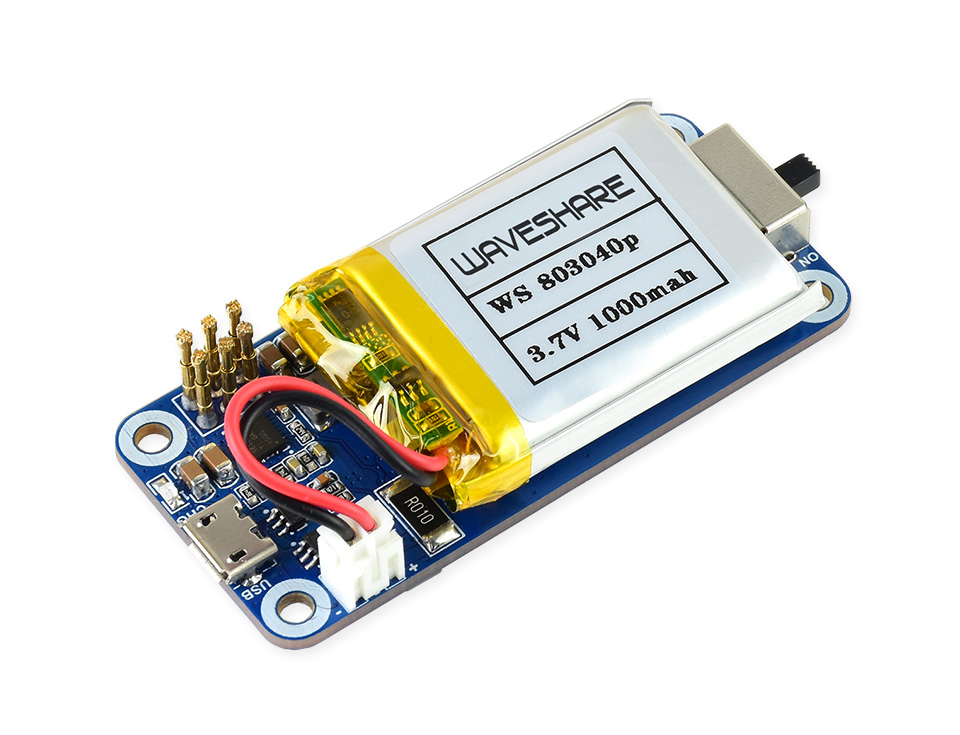
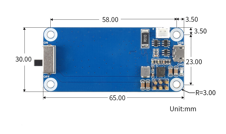
Features At A Glance
The UPS HAT (C) is an uninterruptible power supply module specialized for Raspberry Pi Zero series. It incorporates Li-po battery switching charger with path management, voltage boost chip, and voltage/current monitor which allows monitoring the battery operating status via I2C bus.
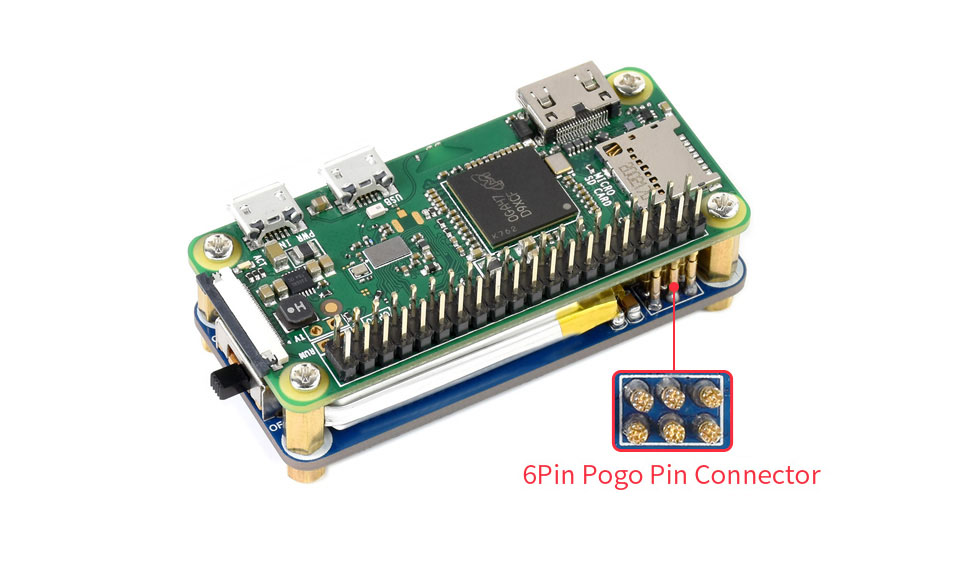
- Onboard spring pogo pins for connecting with Raspberry Pi Zero series boards
- Li-po battery recharge chip, with dynamic path management, more stable power supply
- Voltage boost chip, providing regulated 5V power output
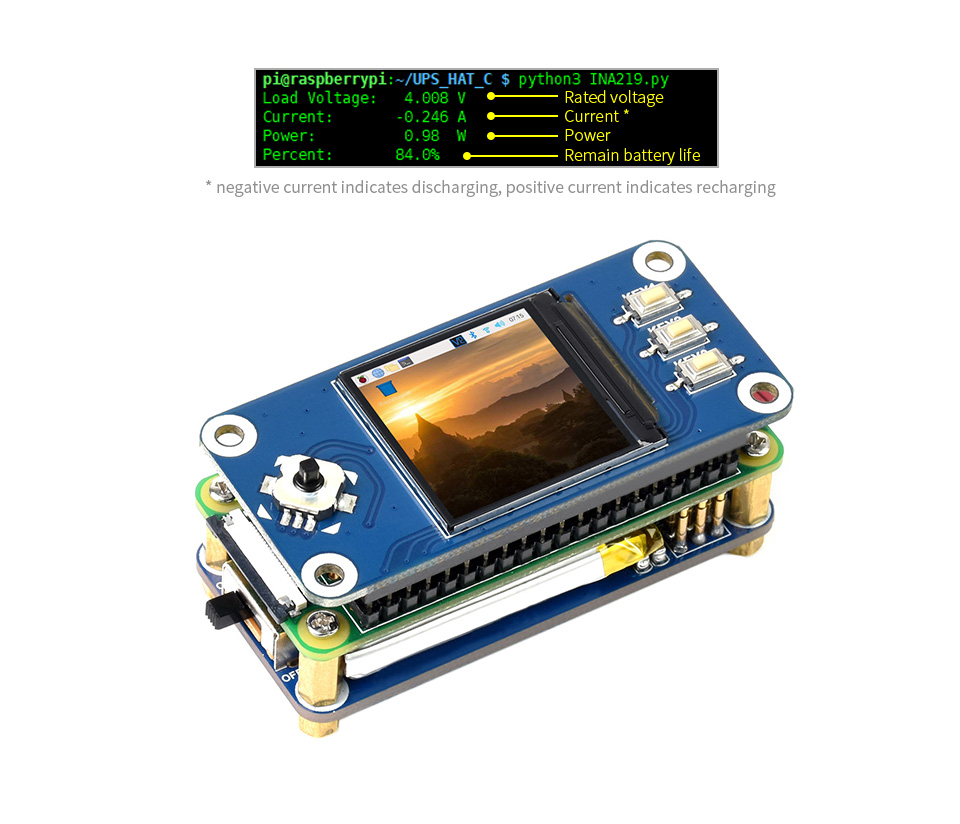
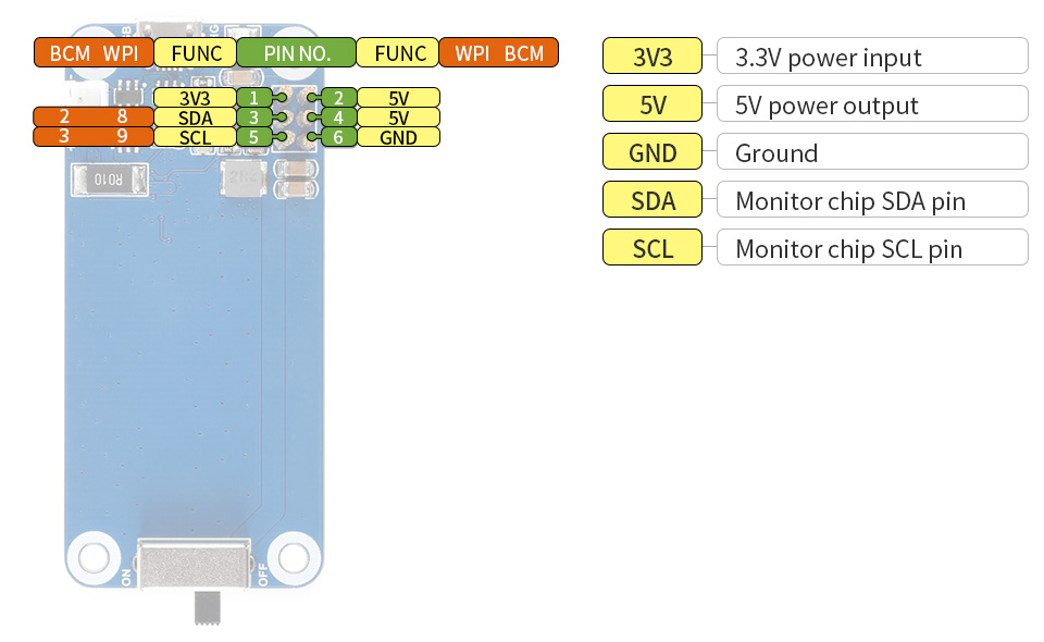
- I2C bus communication, monitoring the battery voltage, current, power, and remaining capacity in real time
- Multi battery protection circuits: over charge/discharge protection, over current protection, and short circuit protection, more safe and stable
- Recharging indicator for monitoring the battery operating status
- Comes with development resources and manual
Specifications
| OUTPUT VOLTAGE | 5V | CHARGER | 5V |
|---|---|---|---|
| CONTROL BUS | I2C | BATTERY | 803040 Li-po battery 1000mAh 3.7V |
| MOUNTING HOLE SIZE | 3.0mm | DIMENSIONS | 65 × 30mm |
Uninterruptible Power
It is able to recharge the battery and provide power output at the same time from external power supply
Automatically switch over to battery output if external power supply is unavailable, keeps the system running without any trouble
Supports Raspberry Pi Zero Series (Pinheader Should Be Soldered),
Allows Attaching Other HATs On The Top
Monitoring The Battery Voltage, Current, Power, And Remaining Capacity Via I2C
When the voltage dips too low, it is possible to save files properly and then shutdown the system by software, to avoid any data loss
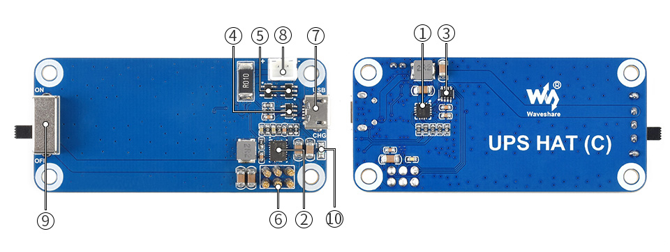
- ETA6003: recharge manager
- TPS61088: voltage boost chip
- INA219: voltage/current monitor
- S8261: Li-po battery protection chip
- FS8205: Li-po battery protection MOS
- Pogo pins: for connecting with Raspberry Pi Zero
- USB recharge port: 5V charger input
- Battery header: for connecting 803040 Li-po battery
- Power indicator
- Recharging indicator
What's in the box?
1 x Uninterruptible Power Supply UPS HAT For Raspberry Pi Zero, Stable 5V Power Output
Resources
WIKI: www.waveshare.com/wiki/UPS_HAT_(C)