
WaveShare


CH344L | Stable Transmission | Multiple Devices Applicable | Multi-OS Compatible
Features At A Glance
- Adopts original CH344L chip, fast communicating, stable and reliable, better compatibility
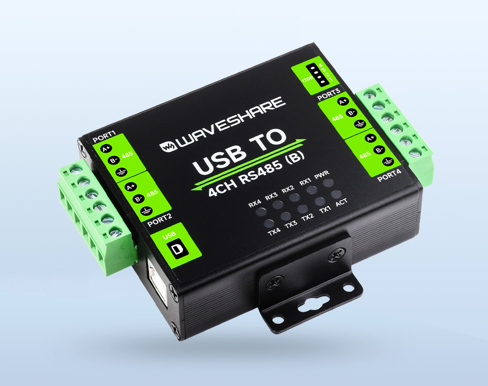
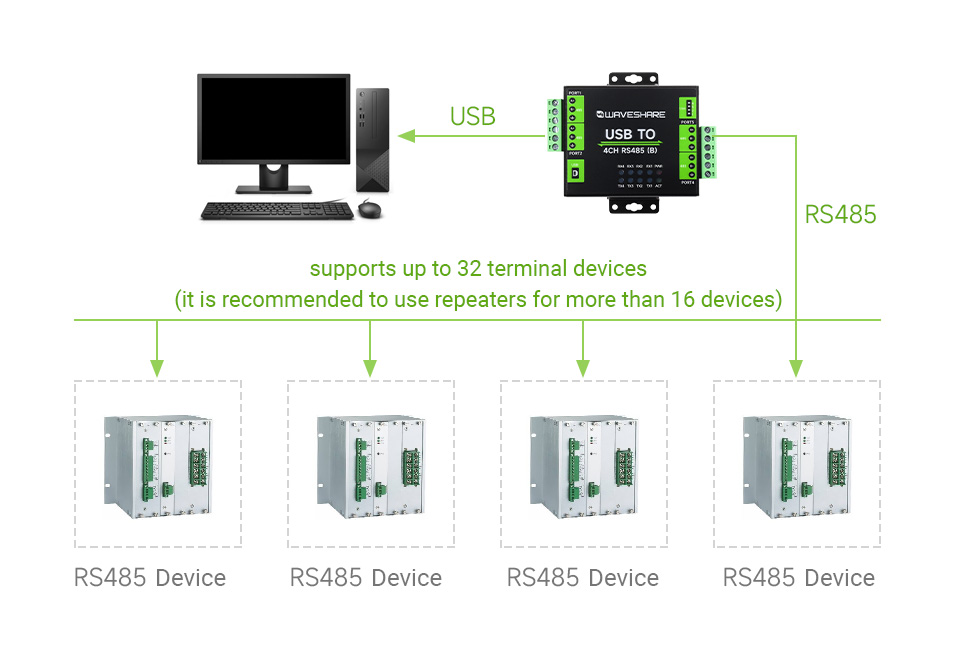
- Supports USB to 4-ch isolated RS485, convenient for expanding multiple RS485 industrial serial devices
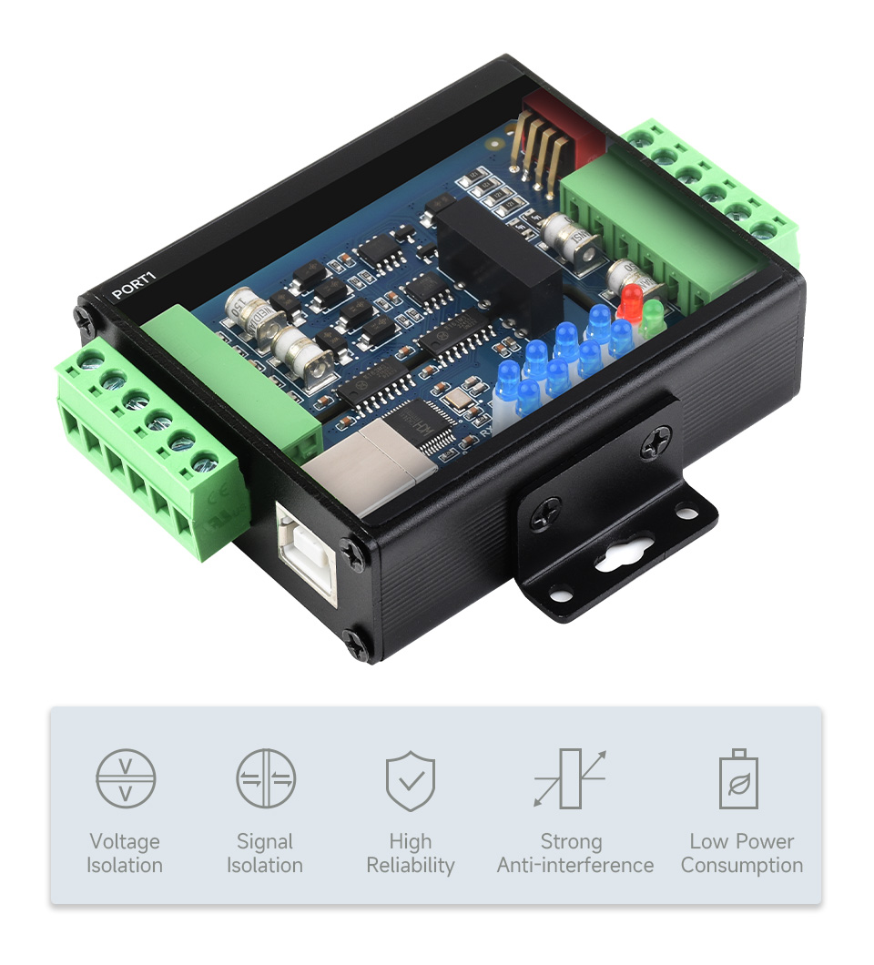
- Onboard unibody power supply isolation, provides stable isolated voltage, needs no extra power supply for the isolated terminal
- Onboard unibody digital isolation, allows signal isolation, high reliability, strong anti-interference, low power consumption
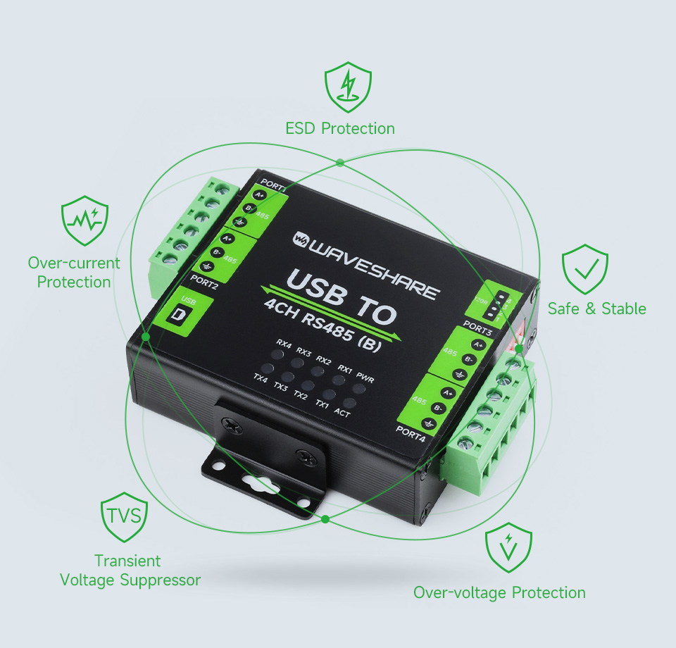
- Onboard TVS (Transient Voltage Suppressor), effectively suppress surge voltage and transient spike voltage in the circuit, lightningproof & ESD protection
- Onboard self-recovery fuse and protection diodes, ensures the current/voltage stable outputs, provides over-current/over-voltage proof, improves shock proof performance
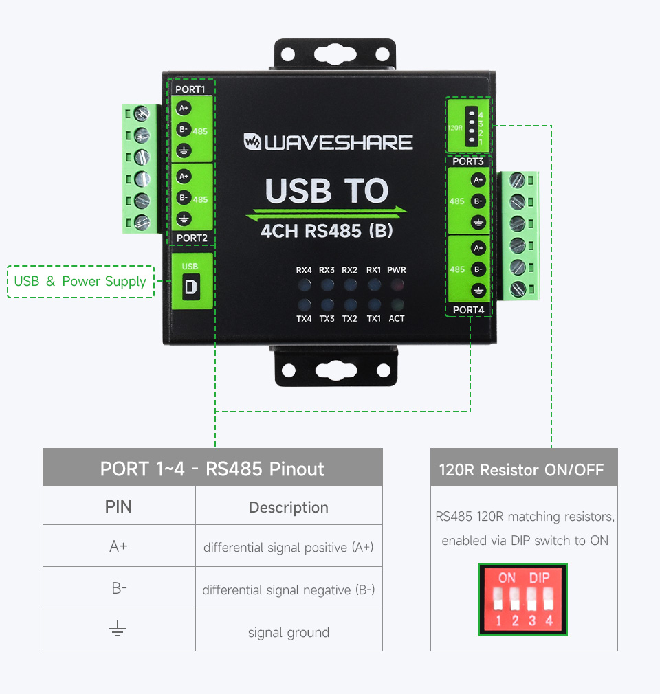
- Onboard RS485 output terminal 120R resistors, enabled/disabled via DIP switch
- 10 LEDs for indicating the power, device configuration status and transceiver status
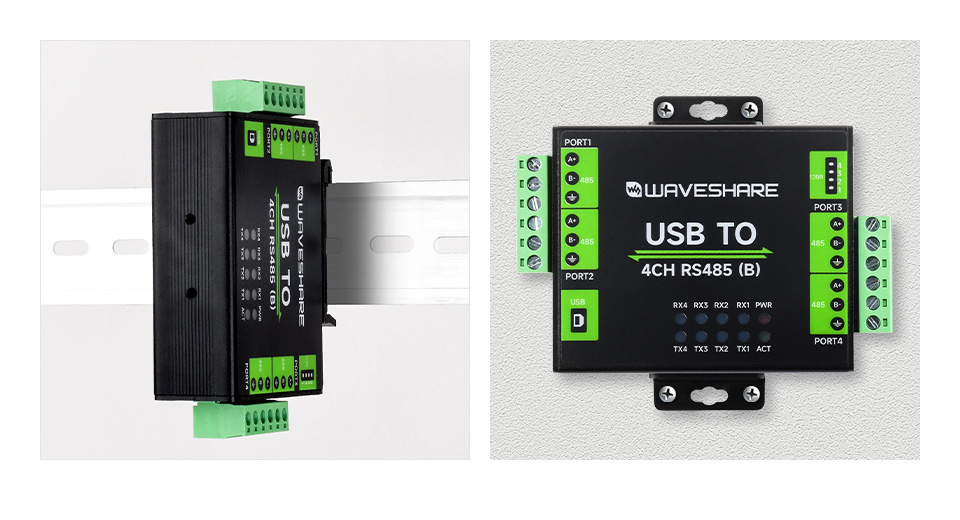
- Industrial grade metal case, supports wall-mount & rail-mount installation, solid and beautiful, easy to install
Specifications
| PRODUCT TYPE | Industrial isolated USB to RS485 converter | |
|---|---|---|
| HOST PORT | USB | |
| DEVICE PORT | RS485 | |
| BAUDRATE | 1200bps ~ 460800bps | |
| USB | Operating voltage | 5V |
| Connector | USB-B | |
| Protection | 500mA resettable fuse, output isolation | |
| ISOLATED RS485 | Connector | Screw terminal |
| Direction control | Hardware automatic control | |
| Protection | 600W lightningproof and surge-suppress, 15KV ESD protection (onboard 120R matching resistors) | |
| Transmission mode | Point-to-multipoints (up to 32 nodes, it is recommended to use repeaters for 16 nodes or more) | |
| INDICATORS | PWR | Power indicator, lights up while the USB is connected and voltage is detected |
| ACT | Status indicator, lights up green while the driver is detected. | |
| RXD | RXD indicator, lights up when the device ports send data back | |
| TXD | TXD indicator, lights up when the USB port is sending data | |
| OPERATING ENVIRONMENT | Temperature | -40 ~ 85℃ |
| Humidity | 5%RH ~ 95%RH | |
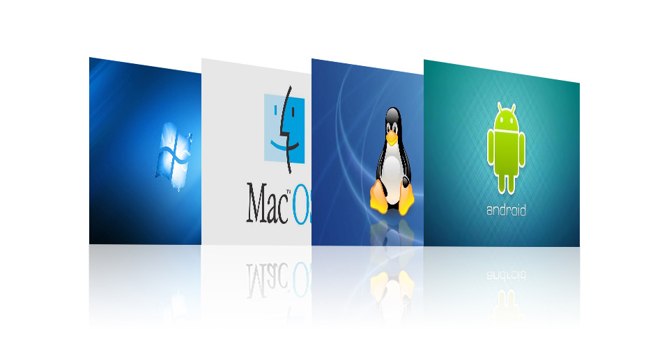
| OPERATING SYSTEM | Win7/8/8.1/10/11, Mac, Linux, Android | |
Safer Isolated Design
- Onboard unibody power supply isolation, provides stable isolated voltage, needs no extra power supply for the isolated terminal
- Onboard unibody digital isolation, allows signal isolation, high reliability, strong anti-interference, low power consumption
Multiple Protection, Safe And Stable
Onboard TVS (Transient Voltage Suppressor), effectively suppress surge voltage and transient spike voltage in the circuit, lightningproof & ESD protection. Onboard self-recovery fuse and protection diodes, ensures the current/voltage stable outputs, provides over-current/over-voltage proof, improves shock proof performance.
Multi System Support
Supports Mac, Linux, Android, Windows 11 / 10 / 8.1 / 8 / 7, Etc.
Transmission Distance Up To 1.2km
The USB Signal Can Be Converted Into 4 Balanced Differential RS485 Signals And The Transmission Rate Is Stable. The Reliable Speed Is 1200~460800bps, The Transmission Distance Is About 1.2km For RS485, And About 5 Meters For USB
Aluminium Alloy Enclosure
Aluminium Alloy Enclosure With Sand Blasting And Anodic Oxidation,
Solid And Durable, Fashionable And Good Hand Feeling
Wall-Mount & Rail-Mount Support, More Flexible For Industrial Installation
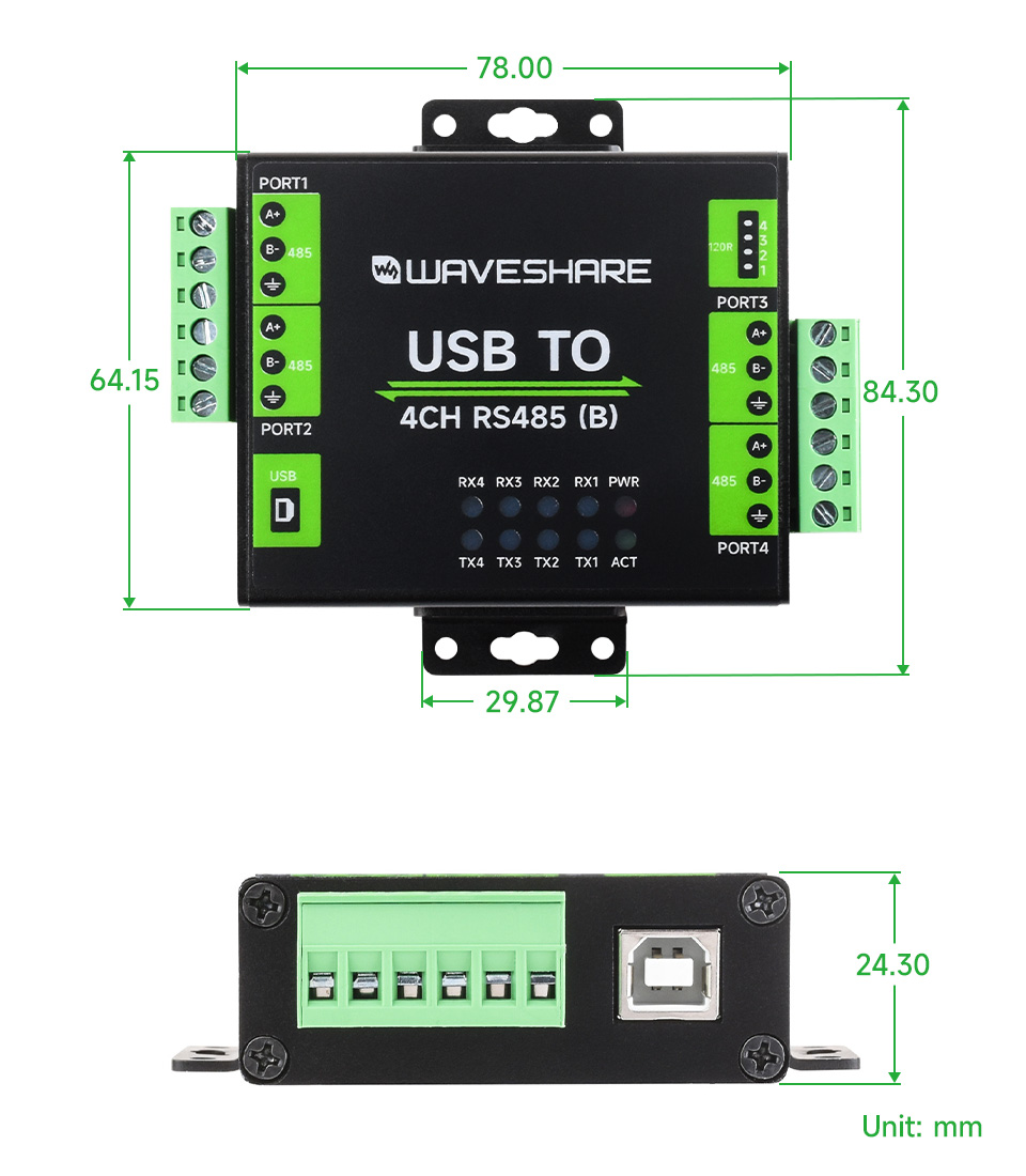
Outline Dimensions
What's in the box?
1 x USB TO 4CH RS485 (B)
1 x Rail-mount buckle
1 x USB type A to type B cable ~1.2m
1 x Screwdriver
Resources
www.waveshare.com/wiki/USB_TO_4CH_RS485_(B)

Modbus RTU Protocol, Multi Isolation Protection Circuits, Safe & Stable & Reliable
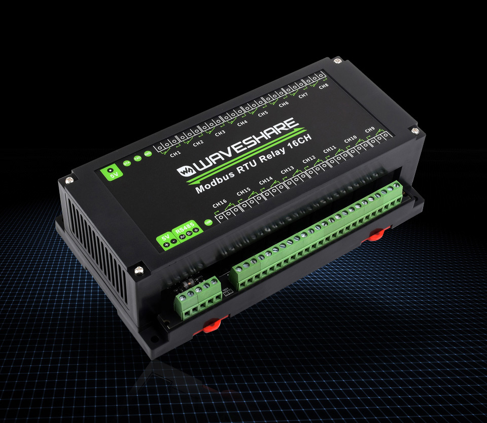
Features At A Glance
This product is an industrial 16-ch relay module controlled via RS485 bus, adopts Modbus RTU protocol, built-in protection circuits such as power supply isolation, magnetical isolation, resettable fuse, and TVS diode, etc. It also comes with an ABS case.
The Modbus RTU 16-Ch Relay is very easy to use. Due to its fast communication, stability, reliability, and safety, it is an ideal choice for industrial control equipments and/or applications with high communication requirements.
- Configurable device address (1~255), multi devices can be cascaded on RS485 bus
- Features flash-on, flash-off function, by passing argument to the command, it is possible to turn on the relay for a while and then close it automatically
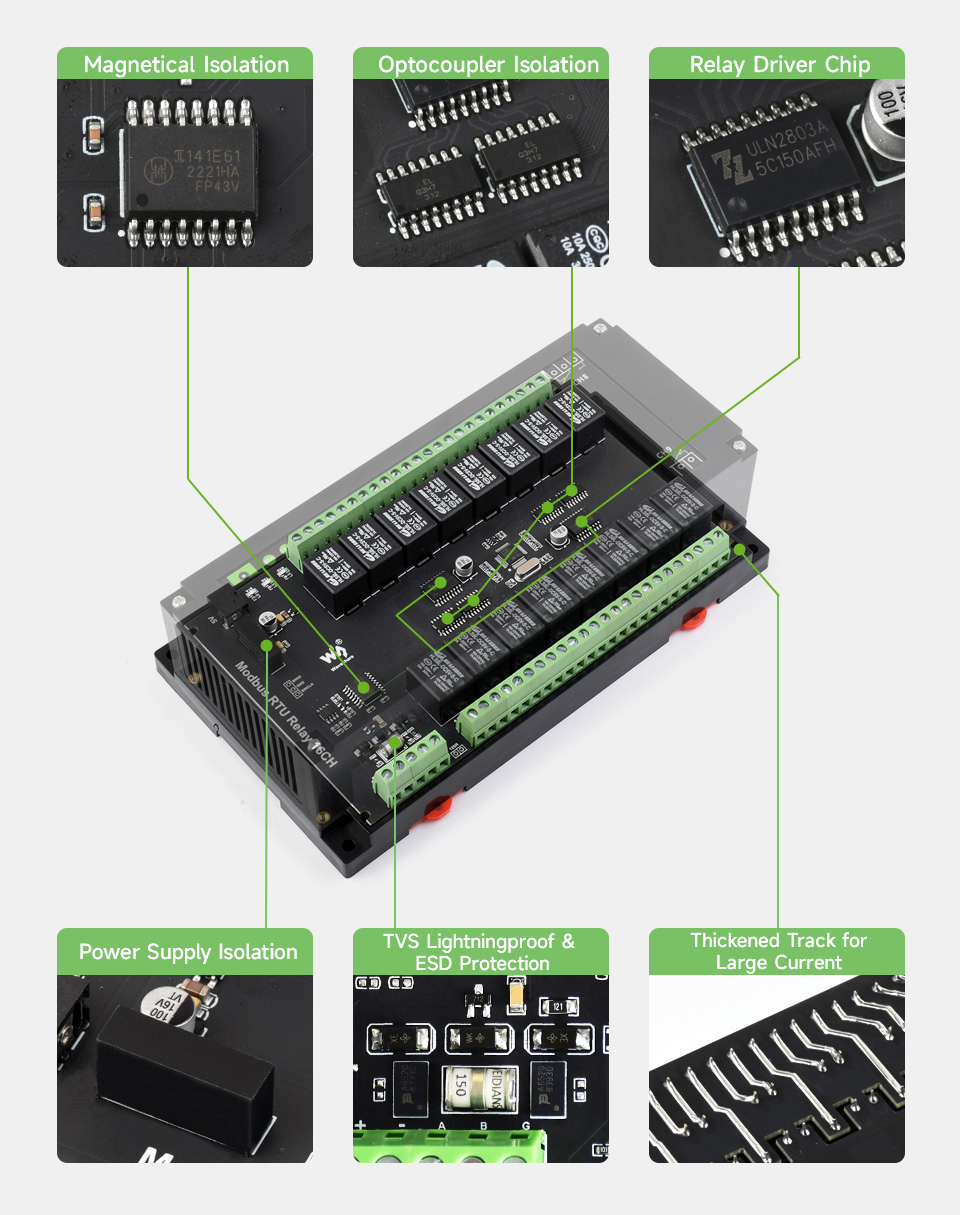
- Onboard unibody power supply isolation, provides stable isolated voltage, needs no extra power supply for the isolated terminal
- Onboard unibody magnetical isolation, allows signal isolation, high reliability, strong anti-interference, low power consumption
- Onboard resettable fuse and TVS (Transient Voltage Suppressor), effectively suppress surge voltage and transient spike voltage in the circuit, provides over-current/over-voltage proof, lightningproof & anti-electrostatic
- Onboard Optocoupler isolation, prevent the relay from being interfered by high-voltage circuit
- Onboard dedicated relay driver chip, with built-in freewheeling diode protection, the driving ability is stronger and more stable
- Reverse-proof circuit, prevent the circuit from being damaged accidentally by incorrect connection
- High quality relay, contact rating: ≤10A 250VAC/30VDC
- Rail-mounted ABS case, easy to install, safe to use
- 3 LEDs for indicating the MCU status and signal transceiving status
Specifications
| OPERATING VOLTAGE | 5V |
|---|---|
| COMMUNICATION INTERFACE | RS485 |
| BAUDRATE | 4800, 9600, 19200, 38400, 57600, 115200, 128000, 256000 |
| DEFAULT COMMUNICATION FORMAT | 9600, N, 8, 1 |
| RELAY CHANNELS | 16 |
| CONTACT FORM | 1NO 1NC |
| COMMUNICATION PROTOCOL | Standard Modbus RTU protocol |
| RS485 ADDRESS | 1~255 |
| LED INDICATORS | STA: MCU indicator, keep flashing when the MCU normally working TXD: TX indicator, lights up when sending data RXD: RX indicator, lights up when receiving data |
Onboard Multiple Isolation Protection Circuit
Multiple Protections, More Safe And Reliable
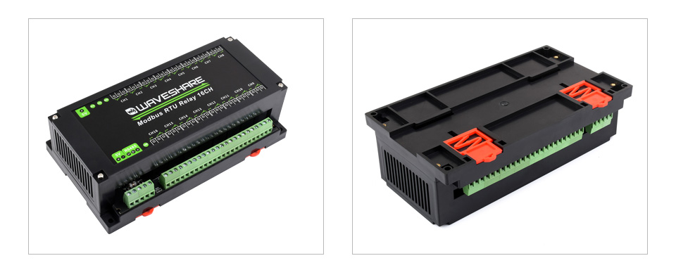
Rail-Mount Case Design
Rail-Mounted ABS Protective Enclosure, Easy To Install, Safe To Use
RS485 Communication
Configurable Device Address (1~255), Multi Devices Can Be Cascaded On RS485 Bus
In Case Of Many Devices Are Cascaded, Or The Communication Distance Is Quite Long, It Is Necessary To Use RS485 Repeaters
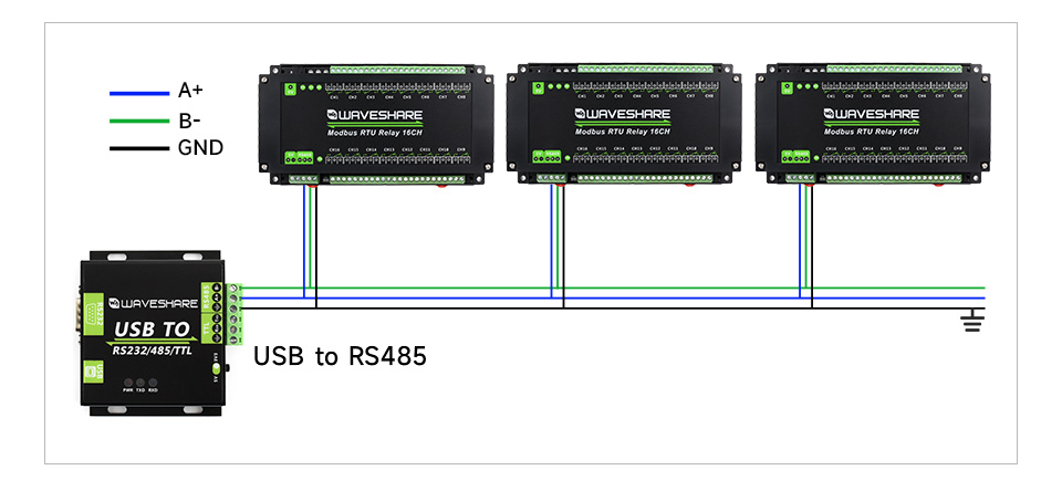
* for reference only, the USB to RS485 is NOT included.
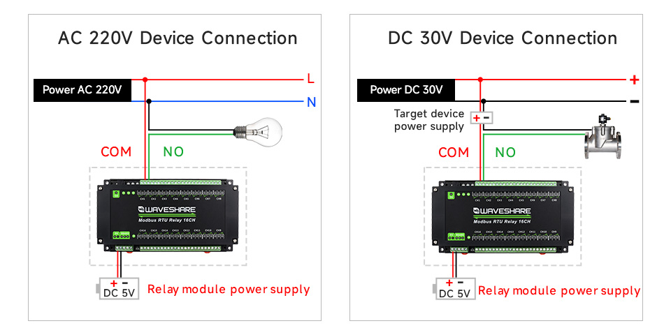
Relay Connection
Contact Rating Of The Onboard Relay Up To 10A 250VAC/30VDC
Directly Controlling 220VAC Home Appliances, Or Devices Below 30VDC
Applications

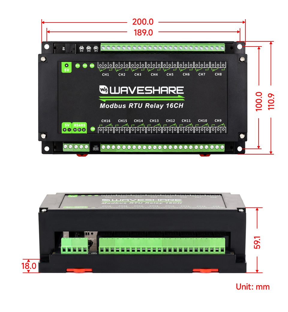
Outline Dimensions
What's in the box?
1 x Modbus RTU Relay 16CH
1 x US plug 5V 2A Power supply (with EU head adapter)
Resources
www.waveshare.com/wiki/Modbus_RTU_Relay_16CH

Rail-mount RS485 serial server
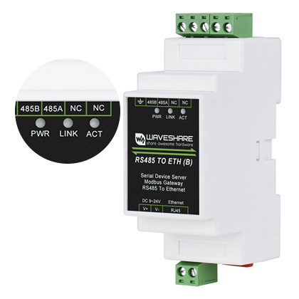
RS485 TO ETH (B)
Common Ethernet port
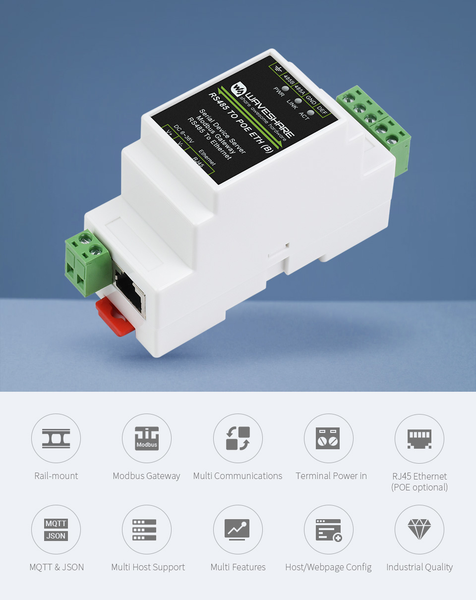
RS485 TO POE ETH (B)
PoE Ethernet port + Electrical isolation
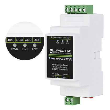
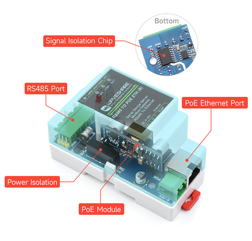
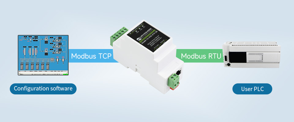
These two versions are the same in software functions, while RS485 TO POE ETH (B) is the hardware upgrade version, support PoE Ethernet port power supply, with power and signal isolation protection, which is safer for industrial applications.
This is an RS485 device data acquisitor / IoT gateway designed for the industrial environment. It combines multi functions in one, including serial server, Modbus gateway, MQTT gateway, RS485 to JSON, etc. The module features RS485 and Ethernet port(POE function is optional), uses screw terminals for power input. Rail-mount case design, small in size, easy to install. It is suitable for applications like data acquisition, IoT gateway, safety & security IoT, and intelligent instrument monitoring...
| PRODUCT | RS485 TO ETH (B) | RS485 TO POE ETH (B) |
|---|---|---|
| Product Type | Serial server, Modbus Gateway, MQTT Gateway | |
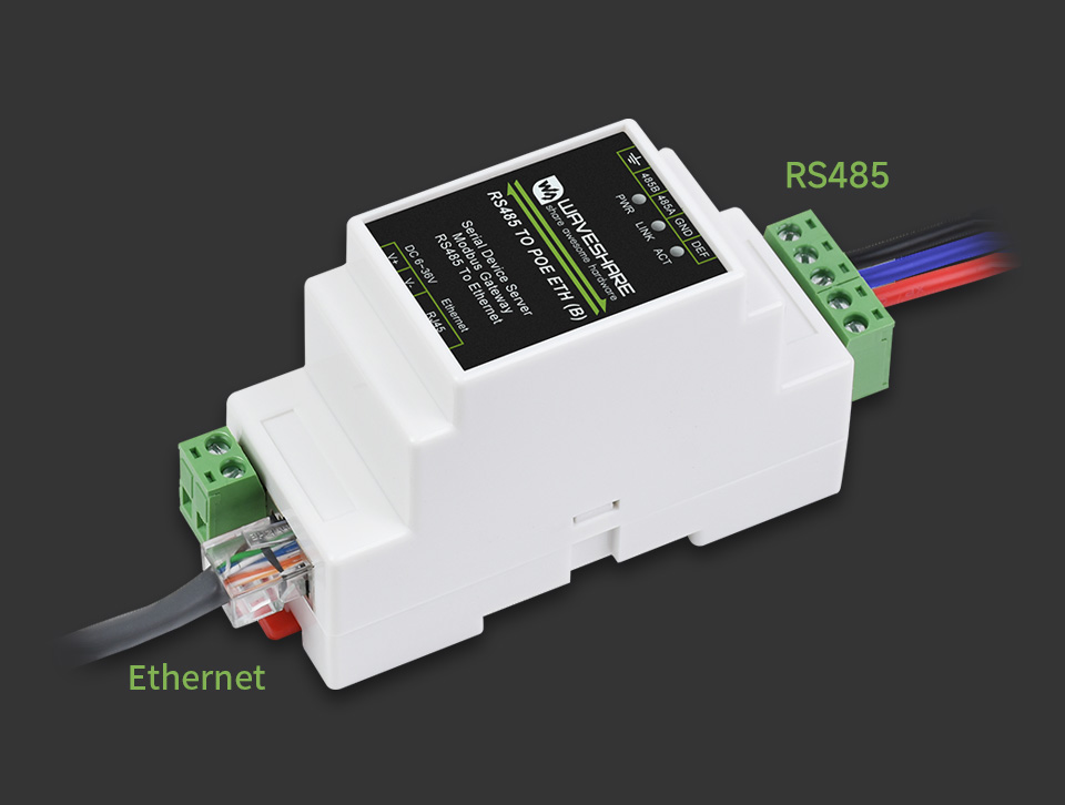
| Basic Function | Bi-directional transparent data transmission between RS485 and Ethernet | |
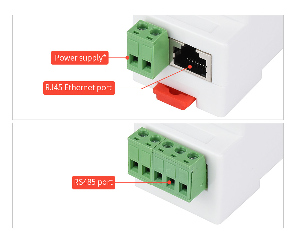
| Communication interface | RS485 port x 1, Ethernet port x 1 | |
| Power supply | 9 ~ 24V DC screw terminal | 6 ~ 36V DC screw terminal, or PoE port |
| Isolation Protection | N/C | Power isolation, Signal isolation |
| COMMUNICATION | ||
| Ethernet | common network port | PoE network port, support IEEE 802.3af standard |
| 10 / 100M auto-negotiation RJ45 connector, 2 KV surge protection | ||
| Serial port | RS485 | Isolated RS485 |
| SERIAL SPECIFICATION | ||
| Baudrate | 300 ~ 115200 bps | |
| Parity bit | none, odd, even, mark, space | |
| Data bit | 5 ~ 9 bits | |
| Flow control | N/A | |
| SOFTWARE | ||
| Protocol | ETHERNET, IP, TCP, UDP, HTTP, ARP, ICMP, DHCP, DNS | |
| Configuration | host, web browser, device management functions library | |
| Communication method | TCP/IP direct communication, VCOM | |
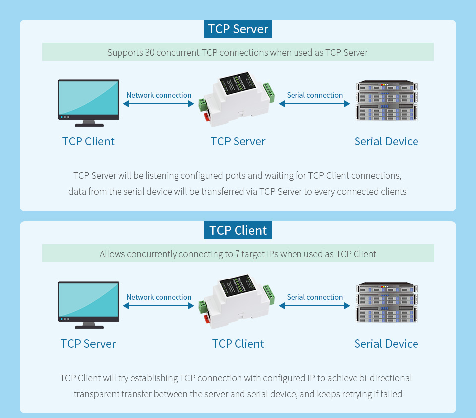
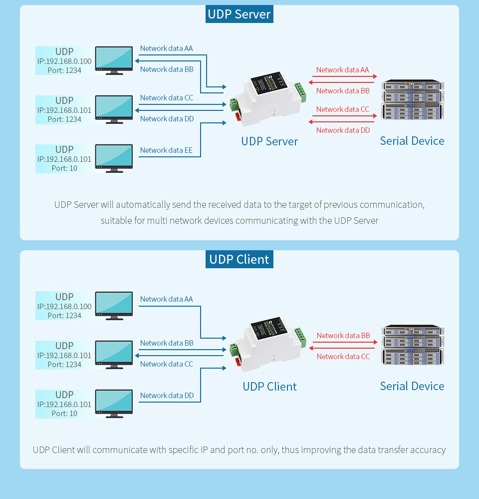
| Operating mode | TCP server, TCP client (coexisting with TCP server), UDP, UDP multicast | |
| ENVIRONMENT REQUIREMENT | ||
| Operating temperature | -40℃ ~ 85℃ | |
| Storage temperature | -40℃ ~ 100℃ | |
| Humidity range | 5% ~ 95% relative humidity | |
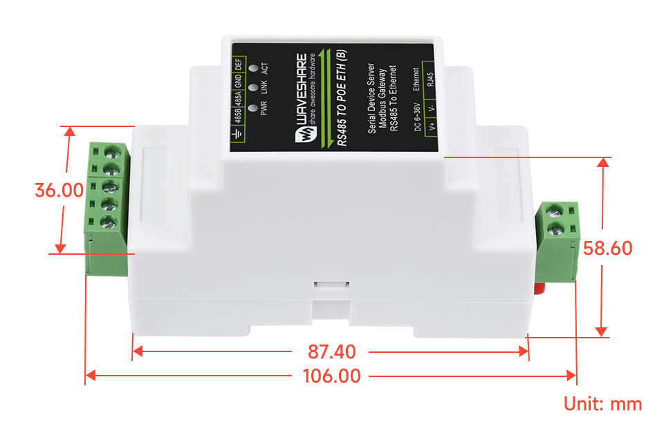
| Dimensions | L × W × H: 87 × 36 × 59 mm | |
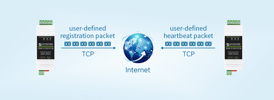
Bi-Directional Transparent Data Transmission Between RS485 And Ethernet
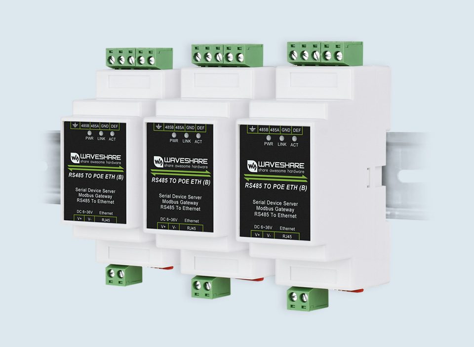
Easy To Combine Multi Rail-Mounted Serial Server Together, More Freely
Suitable For Modbus Gridding Upgrade, Can Be Used With 3D Configuration Software
Supports TCP Server / TCP Client / UDP Mode / UDP Multicast
More Flexible Conversion Between Different Protocols

When used as MQTT gateway, the devices can upload serial data to MQTT server by MQTT protocol through transparent transmission, supported servers including Baidu Cloud MQTT, Alibaba Cloud MQTT, China Mobile OneNet, etc. The acquired Modbus RTU or non-standard serial data can be parsed into JSON format and packaged into MQTTdata packet for uploading.
When used as JSON data acquisition gateway, the devices can be connected to data acquisition instruments through RS485 connection, then acquire data automatically, convert the data into JSON format, and finally post it to server. The acquired data supports Modbus RTU 645 instrument 97 version, 645 instrument 07 version, as well as sorts of non-standard RS485 protocols. The uploaded data format can be configured via host, and the JSON upload protocol can be MQTT protocol, HTTP POST protocol, HTTP GET protocol, and so on.
Different Network Devices Will Be Identified And Responsed Respectively,
No More Crosstalk Issue While Communicating With Multi Network Devices
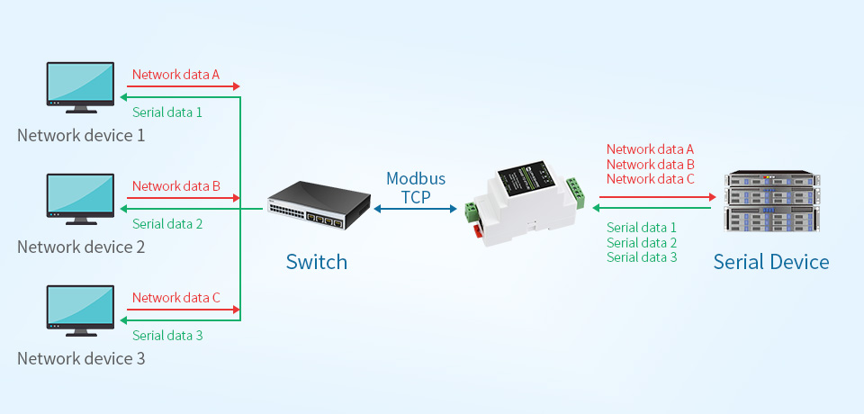
Easy For Cloud Communication And Device Identification
Getting Network Time Info For Serial Output Or Data Upload

Supports Web Browser Configuration, Obtaining Dynamic IP Via DHCP,
DNS Protocol Connected Domain Server Address

Features
- Standard Raspberry Pi connectivity, directly pluggable OR through ribbon cable
- 5 sets of 2x20 pinheaders, connect multi HATs together
- USB external power port, provides enough power supply for multi HATs
- Clear and descriptive pin labels for easy use
- Reserved jumper pads on the bottom side, pin connections are changeable by soldering, to avoid pin conflicts
- Compatible with Raspberry Pi 2B/3B/4B/5/Zero and Zero 2
Note: make sure there are no any pin conflicts between the HATs you want to use together before connecting.
Specifications
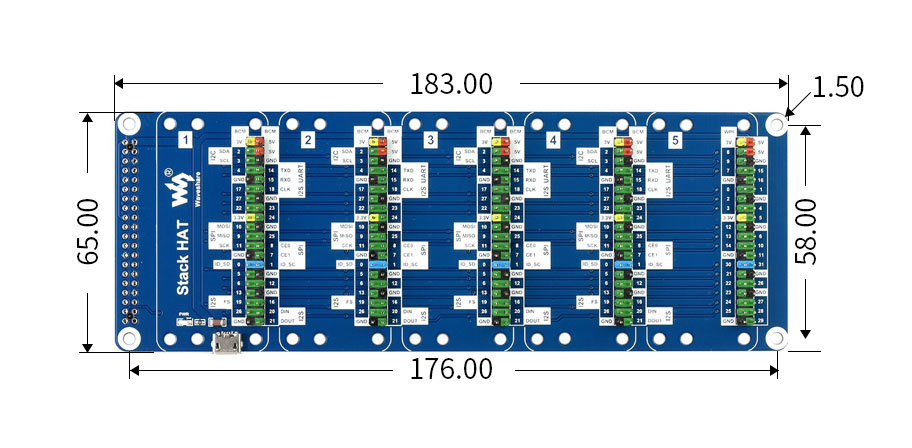
- Dimension: 183mm × 65mm
- Mounting hole size: 3mm
Dimensions
What's in the box?
1 x Stack HAT
1 x Ribbon cable 40PIN
1 x 2x20 male pin header
1 x RPi screws pack (4pcs)
Resources
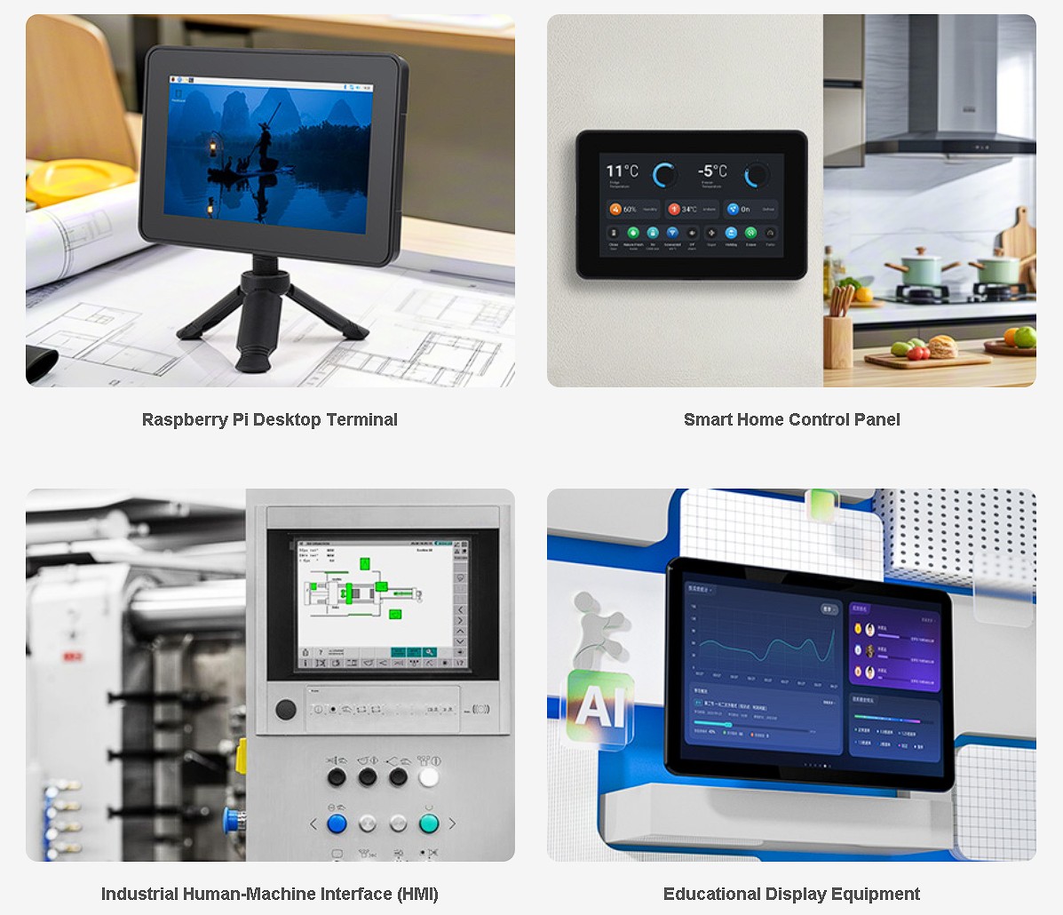
This protective case is engineered for the Raspberry Pi 5 and the official Raspberry Pi Touch Display 2. It features high-precision injection molding for a strong, unibody structure that resists deformation over time. Its sleek industrial design—with smooth lines and rounded edges—makes it suitable for educational setups, office environments, and industrial control panels.
The case supports quick assembly and disassembly, making it easy to install heatsinks, route cables, or swap accessories. It includes multiple mounting holes for flexible installation on desktops or walls (external brackets are NOT included). Rich cut-outs are reserved for GPIO, HDMI, and power ports, and it’s compatible with various Raspberry Pi HATs like PoE and RS485 CAN modules.

Designed to fit the official Raspberry Pi Touch Display 2—it’s ideal for applications like smart home control panels, educational display systems, and industrial HMIs. The interior layout ensures secure placement of both the Pi board and the touchscreen without modification.
Features
- Adopts high-precision injection molding and tooling process, features a robust unibody structure with outstanding strength and dimensional accuracy. Designed to withstand long-term use without deformation, it is suitable for various environments
- A sleek and minimalist industrial design with a modern appearance, smooth lines, and rounded edges, ideal for education, office, and industrial control applications
- Highly compatible with the Raspberry Pi 5 and the official Raspberry Pi 7inch capacitive touch display, with precisely reserved mounting holes. No modification is needed, simply install the Raspberry Pi 5 and DSI touchscreen quickly and securely
- Modular structural design allows for quick assembly and disassembly, facilitating heatsink installation, cable routing, and accessory replacement, enhancing system maintainability
- Reserved multiple mounting holes on the top, bottom, and back for flexible installation, supports external bracket for desktop / wall mounting (the bracket is not included), providing stable support and a comfortable viewing angle
- Reserved rich cut-outs for GPIO header, HDMI port, and power supply port, etc. Supports installing Raspberry Pi HATs, meeting the development needs of various projects
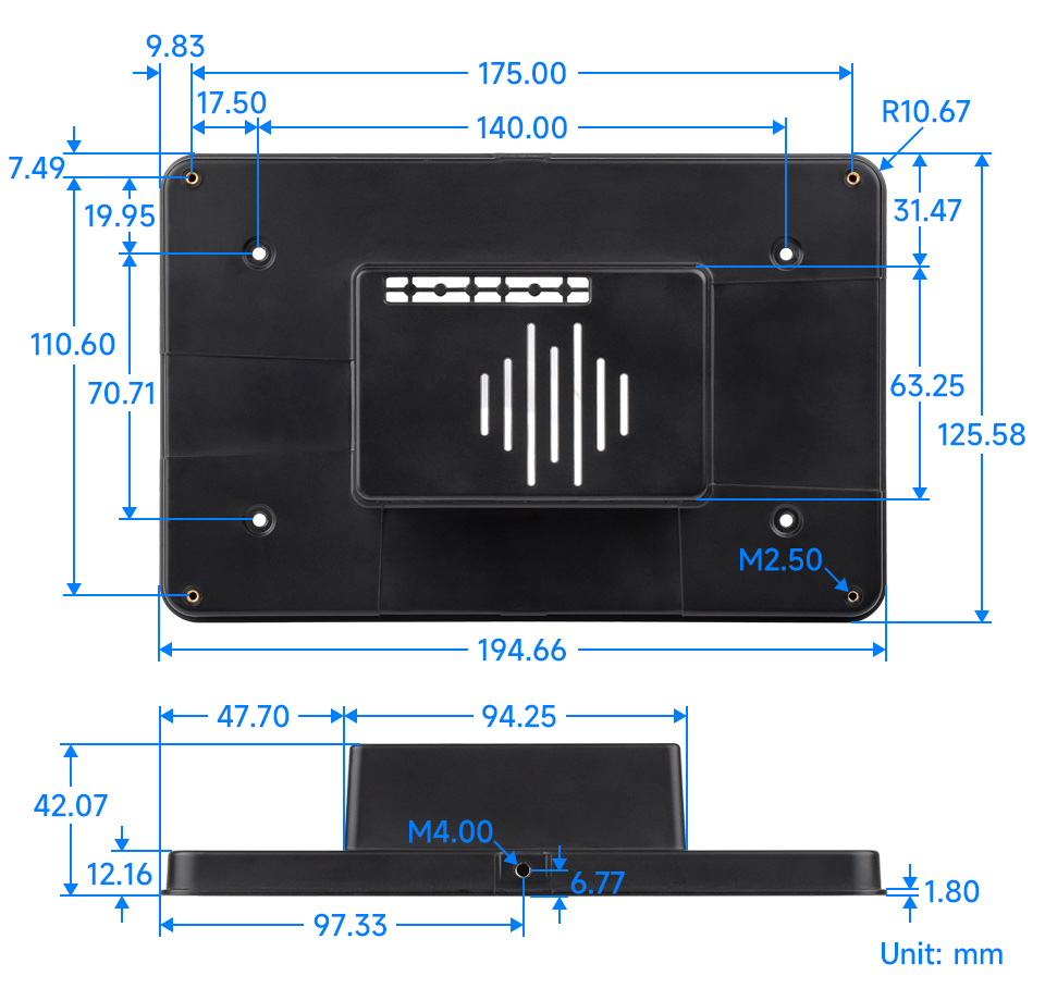
- M4 mounting hole for use with our Universal Mini Tripod
Dimensions
What's in the box?
1 x Protective case for RPi 7-inch Touch Display 2 and RPi 5
1 x Silicon button cap
1 x PM2.5*4mm screw pack
Note: This product consists of the protective case only. The Raspberry Pi 5 and the official Raspberry Pi Touch Display 2 are NOT included. Please get them separately.
Resources
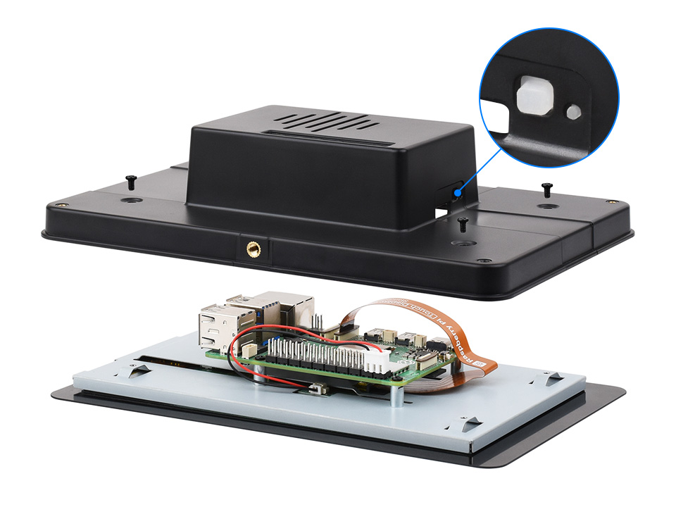
How to install
First, fix the silicone button cap inside the case as picture below, and then use the PM2.5 * 4mm black metal screws to secure the case and screen
- Equipped with Xtensa® 32-bit LX7 dual-core processor, up to 240MHz main frequency
- Supports 2.4GHz Wi-Fi (802.11 b/g/n) and Bluetooth® 5 (LE)
- Built-in 512KB of Static RAM and 384KB ROM, options for 4MB Flash memory with 2MB PSRAM / 8MB Flash memory with 8MB PSRAM
- Castellated module and onboard ceramic antenna, allows soldering direct to carrier boards
- Supports flexible clock, module power supply independent setting, and other controls to realize low power consumption in different scenarios
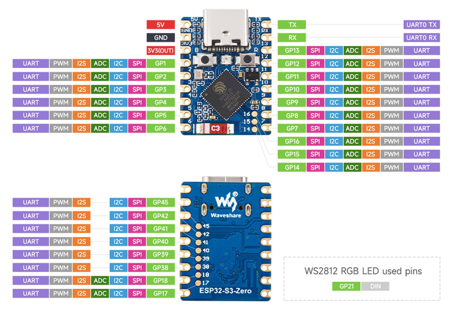
- Integrated with USB serial port full-speed controller, 24 × GPIO pins allows flexibly configuring pin functions
- 4 × SPI, 2 × I2C, 3 × UART, 2 × I2S, 2 × ADC, etc.
Comprehensive SDK, Dev Resources, Tutorials To Help You Easily Get Started
What's on board
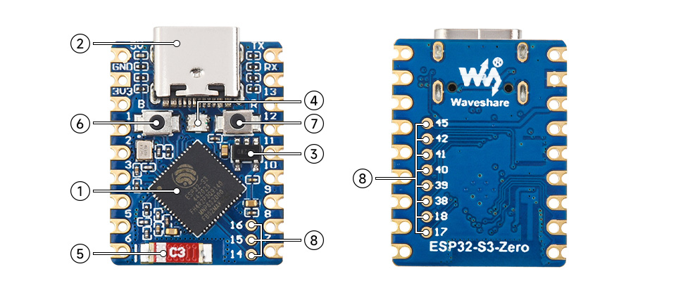
- ESP32-S3 dual-core processor up to 240MHz operating frequency
- USB Type-C Port
- ME6217C33M5Glow dropout LDO, 800mA (Max)
- WS2812 RGB LED
- 2.4G ceramic antenna
- BOOT button -Press it and then press the RESET button to enter download mode
- RESET button
- ESP32-S3 pins
Pin definition
Outline dimensions
What's in the box?
1 x ESP32-S3-Zero-N8R8 with pre-soldered header
Resources
This product is equipped with 32MB Flash and 8MB PSRAM, with pre-soldered headers and external dual-band Wi-Fi antenna.
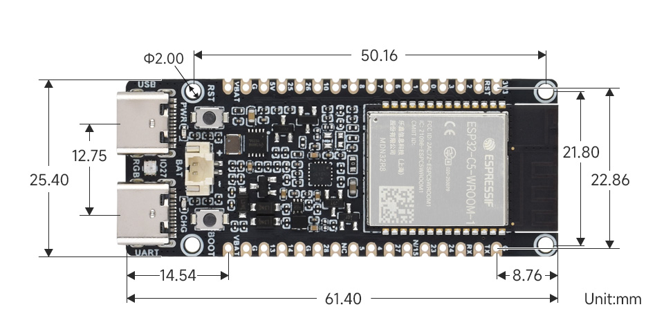
The ESP32-C5-WIFI6-KIT is a development board designed by Waveshare based on the ESP32-C5-WROOM-1 module for dual-band Wi-Fi and multi-protocol IoT gateway applications. The ESP32-C5 is a single-core RISC-V chip, supports dual-band Wi-Fi 6 (2.4GHz and 5GHz), and integrates BLE 5, Zigbee, and Thread protocols for flexible use as a smart home hub or cross-protocol communication gateway.
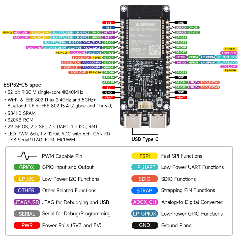
Equipped with 240MHz RISC-V processor, 384KB Static RAM, 8MB PSRAM, and provides options for 16MB or 32MB Flash, enables stable handling the concurrent tasks of multiple protocol stacks and running medium-load applications. Developers can leverage mature development frameworks such as ESP-IDF and Arduino for rapid prototyping and product implementation, making it suitable for IoT scenarios such as smart gateways and multi-protocol device integration.
Key features include
- Adopts ESP32-C5-WROOM-1 series module with RISC-V 32-bit processor, up to 240MHz main frequency
- Integrated with 384KB Static RAM, 320KB ROM, and 8MB PSRAM, with options for 16MB or 32MB Flash
- Integrated 2.4GHz and 5GHz dual-band Wi-Fi, Bluetooth 5 (LE), and IEEE 802.15.4 (Zigbee 3.0 and Thread) wireless communications, with outstanding RF performance
- Onboard batt. recharge management module, with reserved 3.7V MX1.25 Lithium batt. header for external batt. power supply
- USB Type-C port, easier to use
- Castellated module allows soldering directly to carrier boards, with rich peripheral interfaces
- Supports multiple low-power operating modes, enabling flexible adjustment of the balance between communication range, data rate, and power consumption to meet the power requirements of various application scenarios
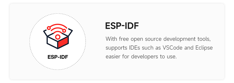
- Supports ESP-IDF, Arduino IDE - Comprehensive SDK, Dev Resources, Tutorials To Help You Easily Get Started
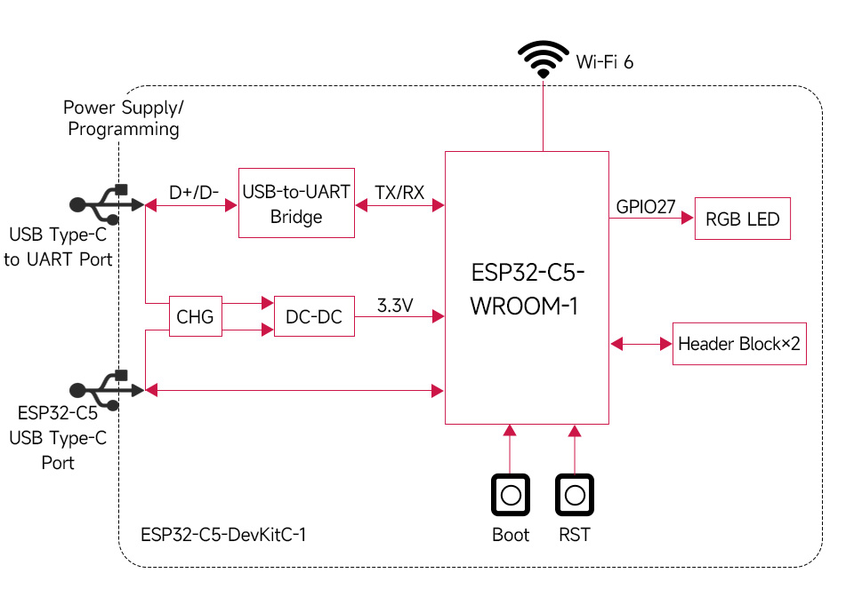
Function Block Diagram
Pinout Definition
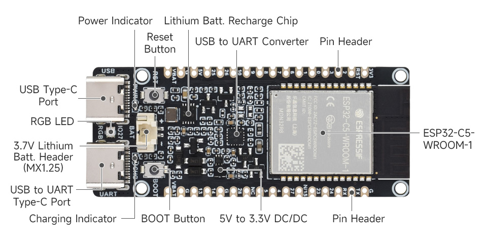
Onboard Resources
With external dual-band Wi-Fi antenna
| Frequency range | 2400 ~ 2500 / 5150 ~ 5850 MHz | Maximum power | 10 W |
|---|---|---|---|
| Bandwidth | 100 ~ 700 MHz | Dimensions | 109 × 10 (mm) |
| VSWR | ≤1.92 | Connector | SMA male central pin |
| Peak Gain | 2±0.5 dBi | Body Material | TPEE |
| Output Impedance | 50 Ω | Operating Voltage | -20˚C ~ + 70˚C |
| Polarisation | Vertical | Radiation | Omnidirectional |
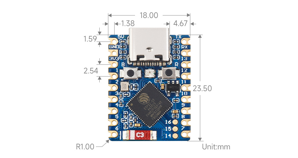
Outline Dimensions
What's in the box?
1 x ESP32-C5-WIFI6-KIT-N32R8-U with pre-soldered headers
1 x Antenna
Resources

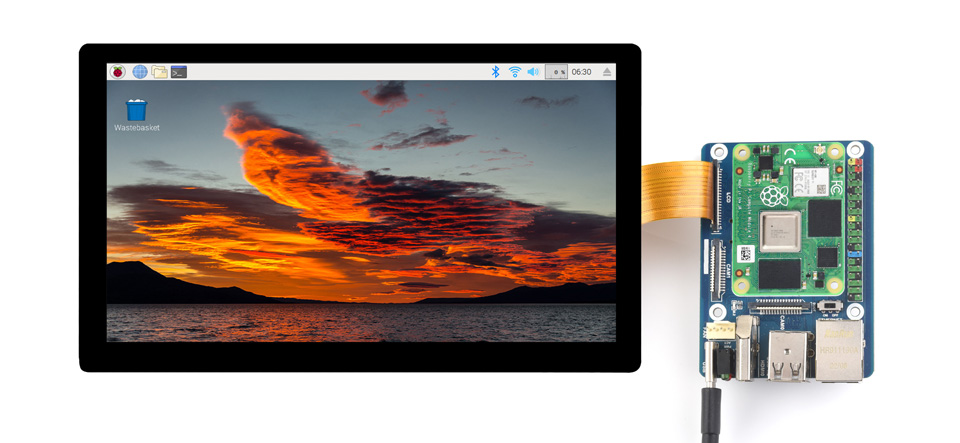
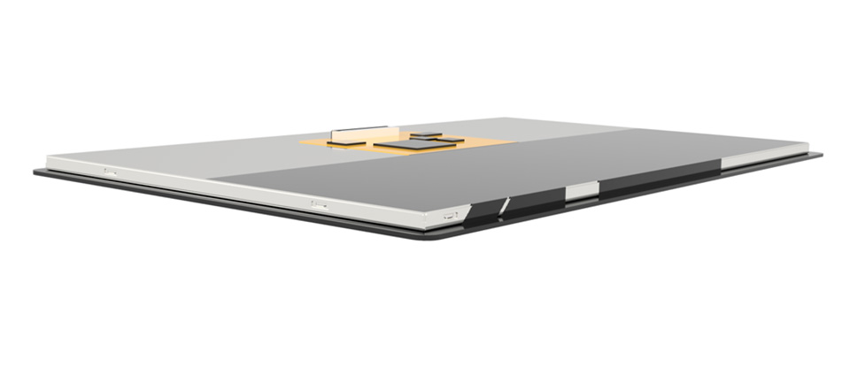
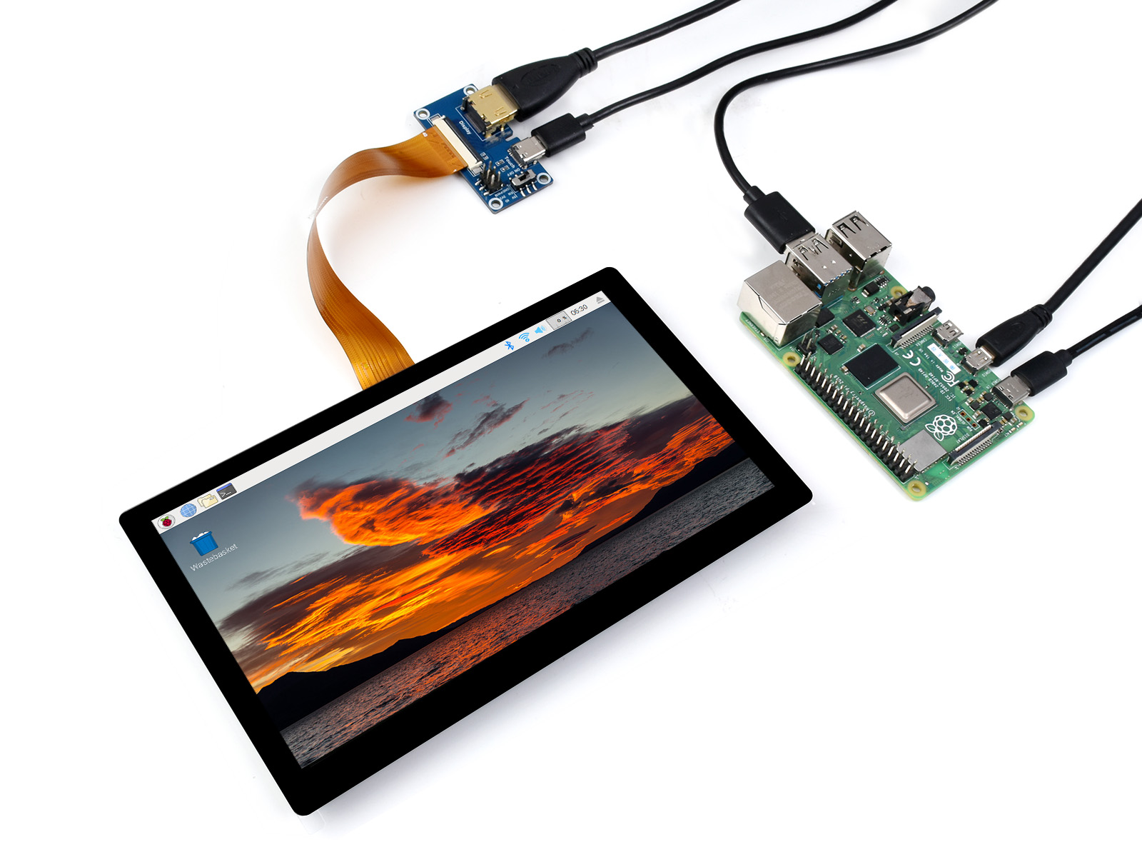
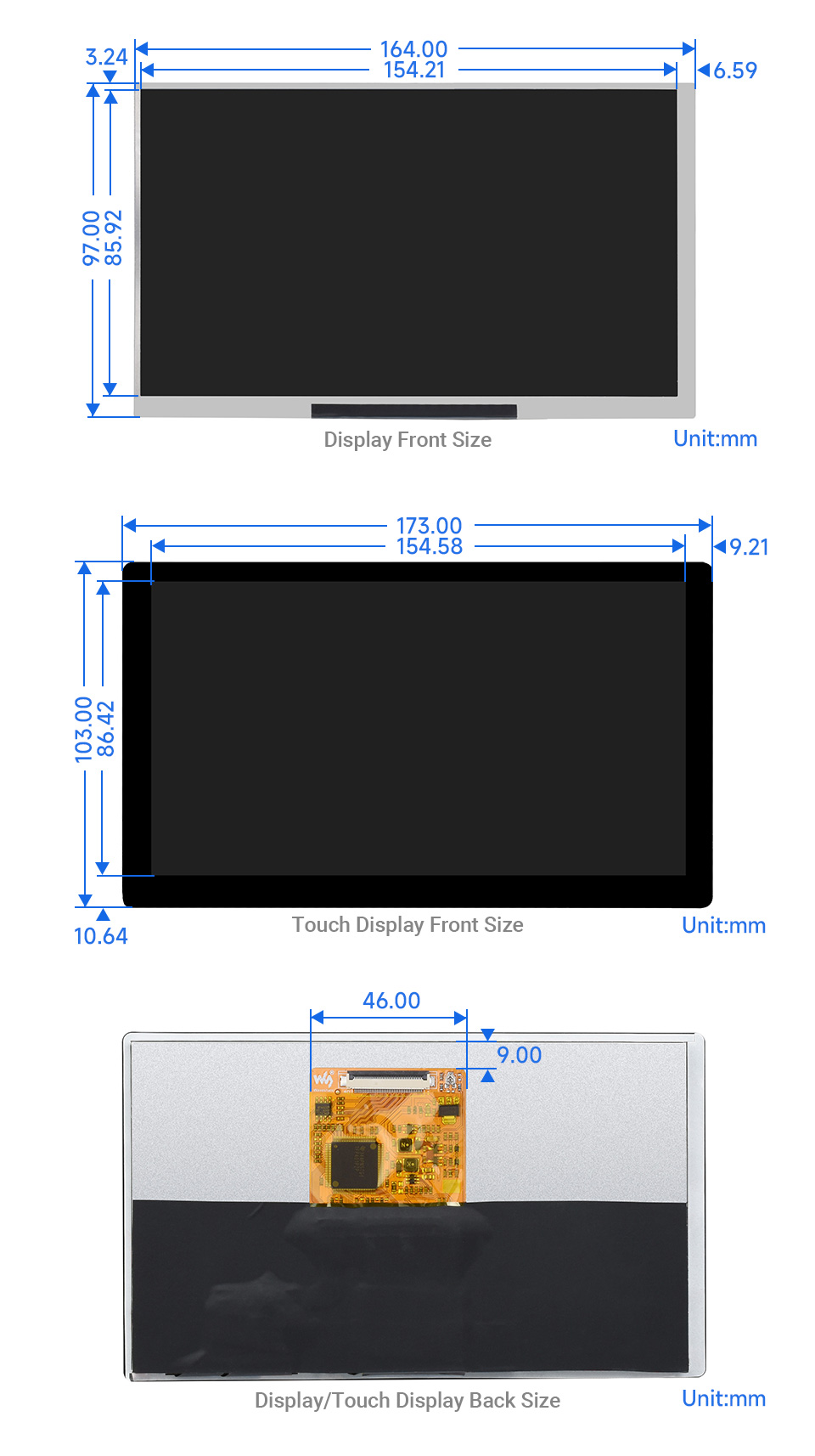
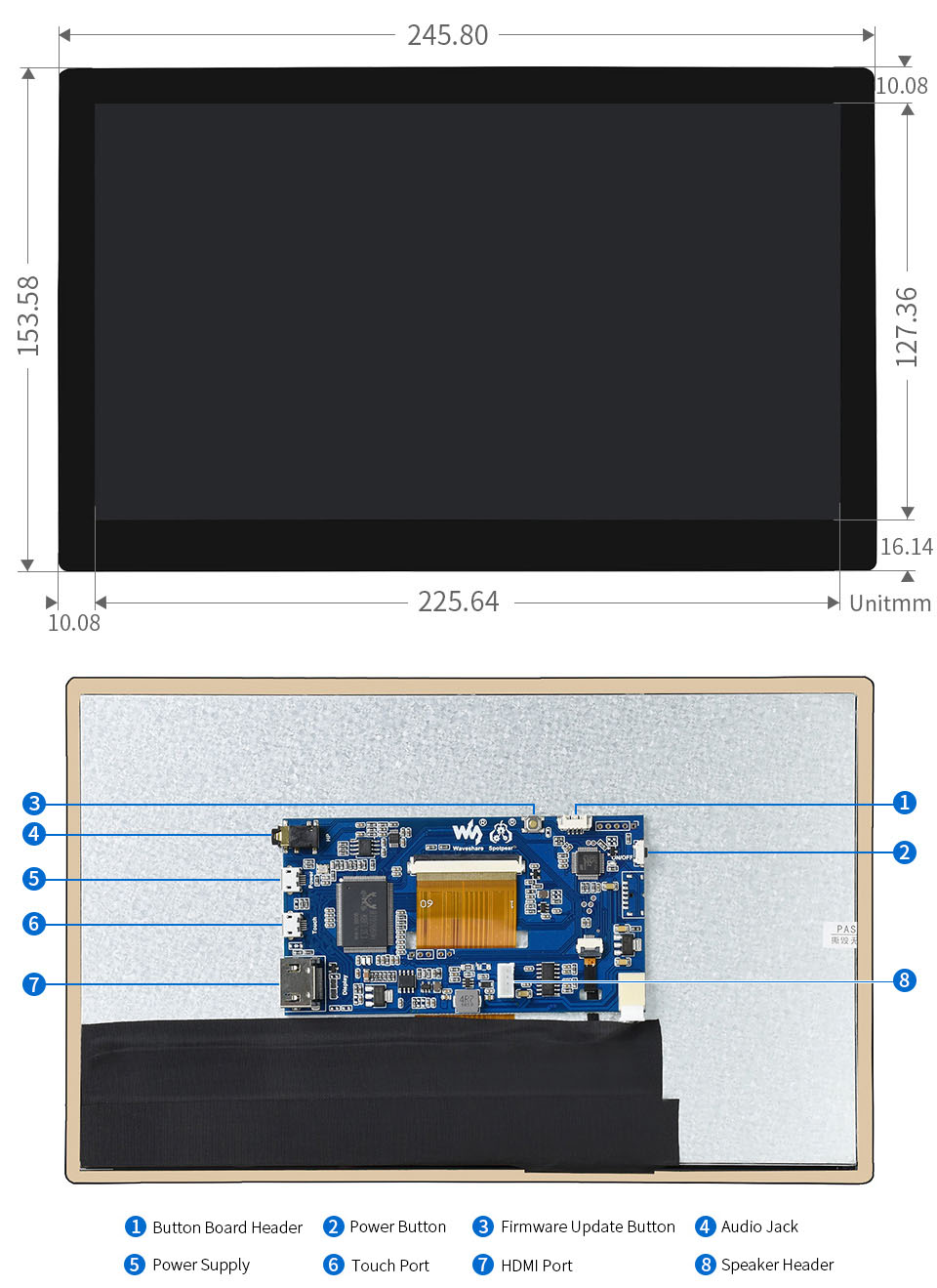
Integrated Structure | Thin and Light Screen Design
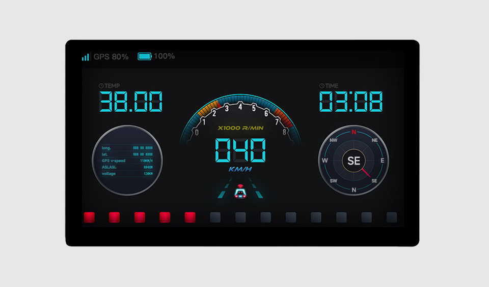
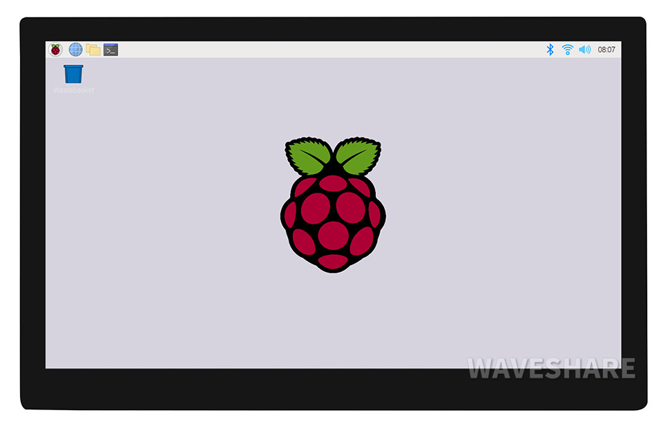
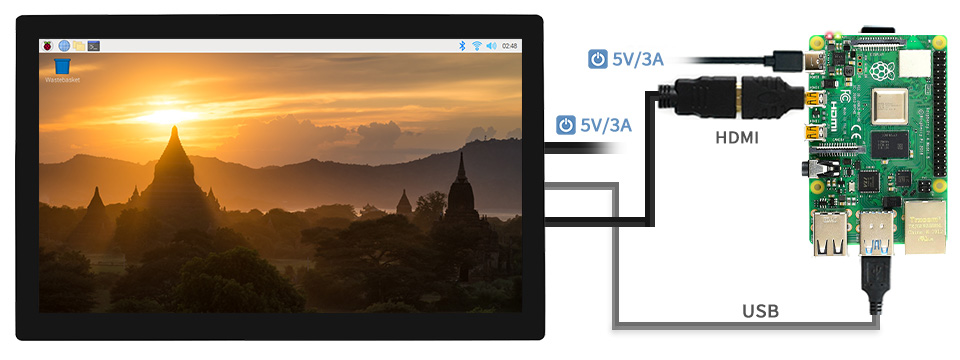
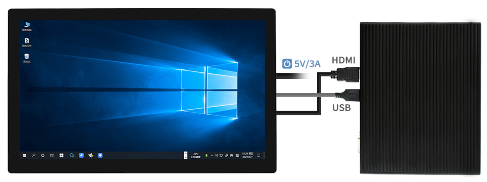
Support Windows / Linux / Android main board which has HDMI signal and USB touch signal
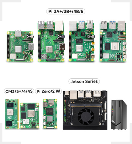
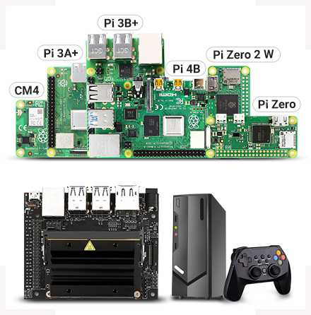
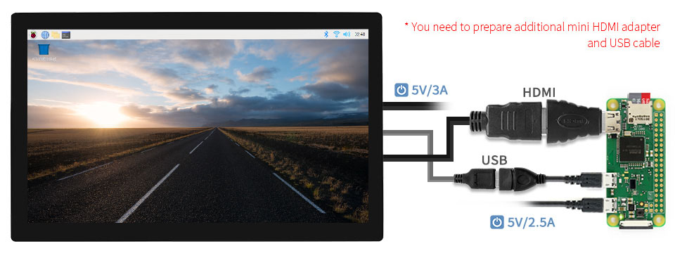
All versions of Raspberry Pi
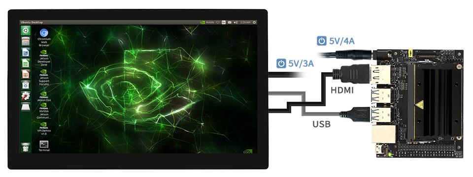
Jetson Series Boards
Windows PC
Provide secondary development resources to facilitate integrated design
Boost simple development for embedding engineering applications quickly
- for reference only, the CM4 board and CM4 base board are NOT included in the package, please refer to the package content for detailed part list.
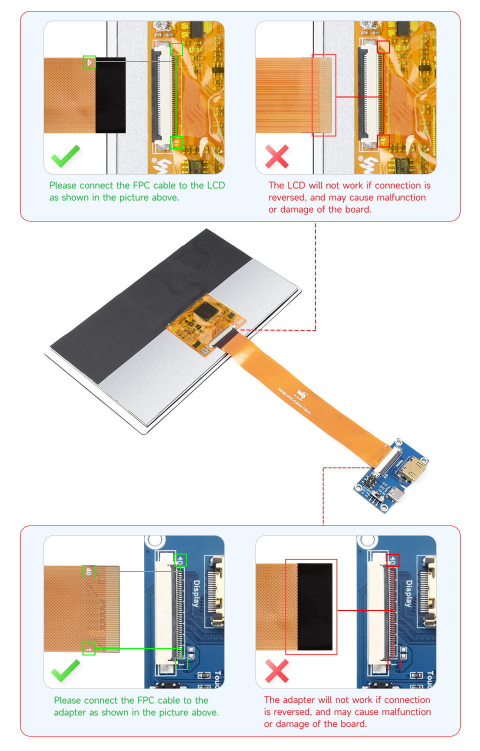
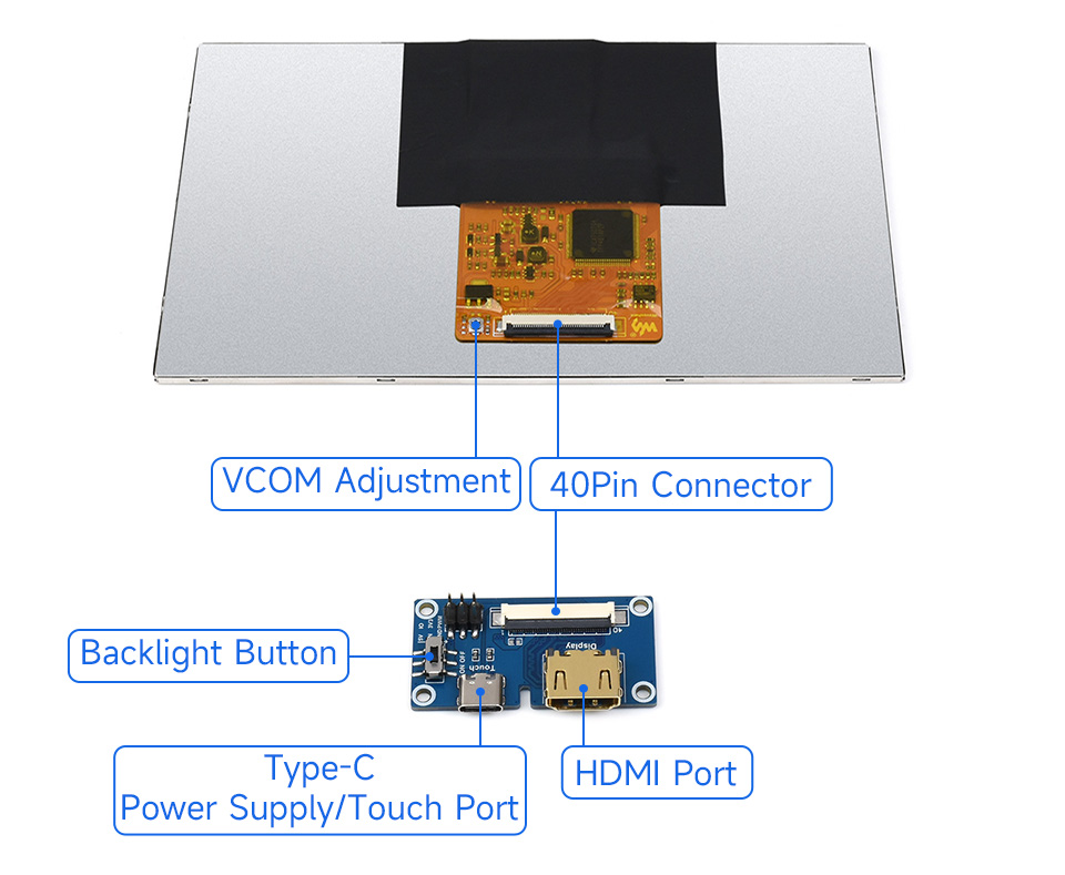
Different with the conventional connection method, integrate 40PIN multi-function interface for one-cable communication. Integrate the driver circuit into an FPC cable, the thinnest only needs 3mm thickness space.

Wider color gamut
Color gamut of this QLED display is up to: NTSC 78%, sRGB 92%
- This function is only available on the QLED version
More pure chroma
chroma of QLED increases 58.3%, makes the color more pure, more vivid
- This function is only available on the QLED version

Longer lifetime
Due to its inorganic characteristic, the color life of QLED could be up to 60000 hours without color degradation
- This function is only available on the QLED version

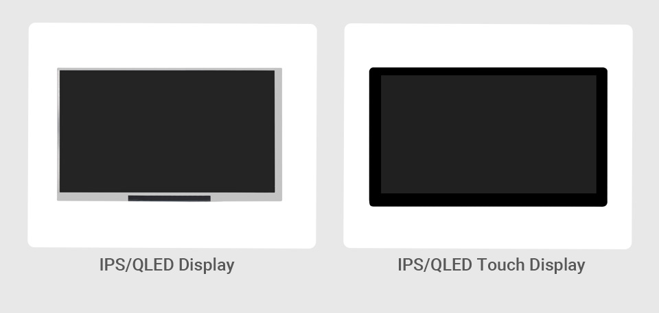
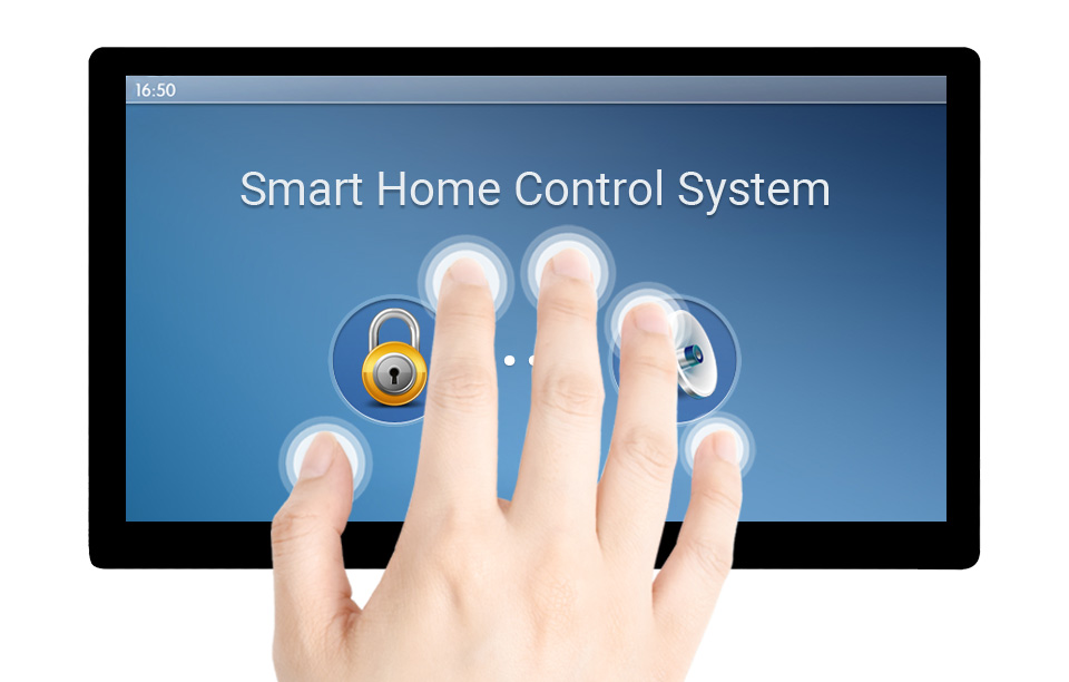
Gently touch, and see what you get, enjoy multi-point UI interaction via Flexible operation. Adapting touch function with USB signal, support 5-point touch
- This function is only available on the Touch Display version
For the first use, it is recommended to use development adapter for connection
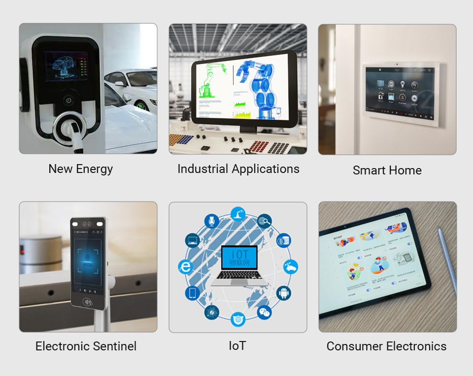
New energy, electronic sentinel, human-machine interface, smart home
IoT, Industrial applications, consumer electronics

Supports Ubuntu / Kali / WIN10 IoT, single point touch, driver free
Supports Retropie, driver free
Supports all versions of Raspberry Pi
Working with Raspberry Pi 4
Working with Raspberry Pi 3B+
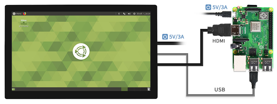
Working with Raspberry Pi Zero W
Working with AI Computer Jetson Nano
Working with mini PC
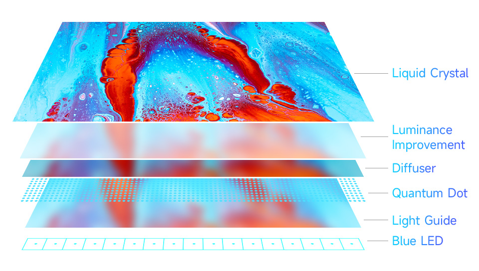
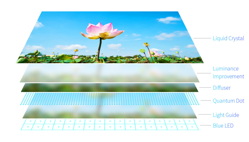
QLED Panel
Wider color gamut
Color gamut of this QLED display is up to: NTSC 96%, sRGB 100%
More pure chroma
Chroma of QLED increases 58.3%, makes the color more pure, more vivid

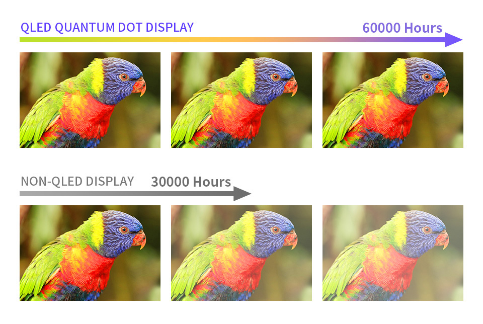
Longer lifetime
Due to its inorganic characteristic, the color life of QLED could be up to 60000 hours without color degradation

Up to 10-point touch, depending on the operating system. 2) up to 6H hardness G-G toughened glass panel.

* audio output via earphone/speaker port.
Resources

Electronic Shelf Label Series
low power, wide viewing angle, paper-like effect without electricity
Ideal for price tags, shelf labels, industrial instruments...
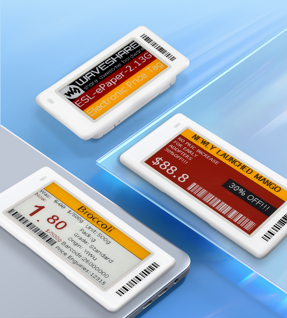
- Red/yellow/black/white 4-color e-paper display, options for 2.9inch
- No backlight, keeps displaying last content for a long time even when power down
- Ultra low power consumption, basically power is only required for refreshing
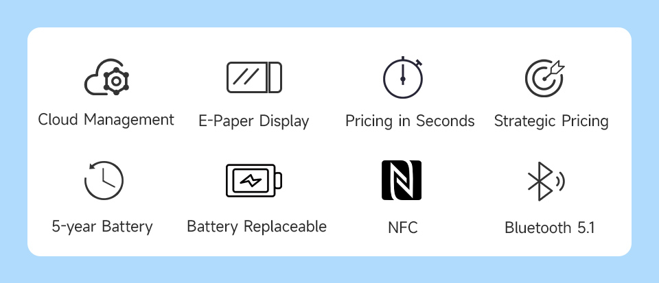
- Cloud platform support, enabling image refresh via ESL-Gateway-AP base station
- 0 ~ 40°C operating temperature, suitable for common usage scenarios
- Built-in replaceable battery, with ultra-long battery life of approx. 5 years
- ABS plastic case, dustproof and better protection
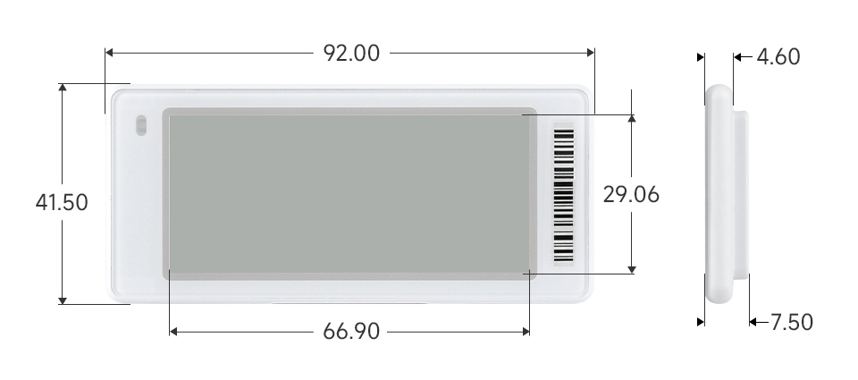
| ESL-ePaper-2.9G | |||
|---|---|---|---|
| Display Technology | E-Paper display | Active Display Area | 66.9 × 29.06mm |
| Standard | BLE 5.0 | Operating Frequency | 2.4 ~ 2.485GHz |
| Resolution | 296 × 128 pixels | Battery Life | up to 5 years |
| Pixel Density (DPI) | 112 | Battery Capacity | 1200mAh |
| Display Color | Red/Yellow/Black/White | Operating Temperature | 0~40℃ |
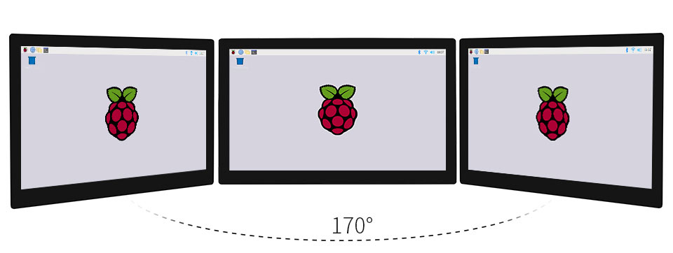
Meets viewing needs from all angles, with a nearly 180° viewing angle

ESL-ePaper-2.9G
What's in the box?
1 x 2.9inch Dot Matrix e-Paper display
Resources