
WaveShare


DO NOT put any non-rechargeable battery, like dry cell, into the battery holder. Serious consequences including explosion may occur if you try to charge a non-rechargeable battery.
SAFETY MEASUREMENTS:
- Li-ion and Li-po batteries are quite unstable. They may cause fire, personal injury, or property damage, if they're not properly recharged or used.
- Do not reversely connect the polarities when recharging or discharging the battery. Do not use inferior charger/charging panel to recharge the battery.
- Do not mix use old batteries with new ones, avoid using batteries of different brands.
- When buying Lithium battery, should always make sure the battery specification is compatible with the expansion board. Choose batteries from formal manufacturer, and ensure the batteries will work stably and safely by aging test.
- Lithium batteries have limited cycle life, they will also deteriorate as time goes by. Should be replaced with new ones when the batteries reaching their max cycle life, or working over two years, whichever comes first.
- Should be placed carefully and properly, keep it away from inflammables and explosives articles, away from children, avoid any safety accident caused by careless storage.
Overview
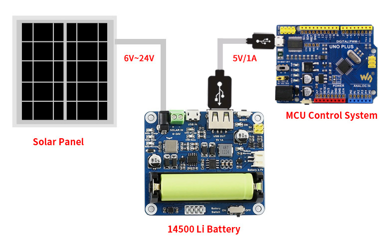
This solar power management module is designed for 6V~24V solar panel. It can charge the 3.7V Li battery through solar panel or USB connection, and provides 5V/1A regulated output.
The module features MPPT (Maximum Power Point Tracking) function and multi protection circuits, therefore, it is able to keep working with high-efficiency, stability, and safety. It is suited for solar powered, low-power IoT, and other environmental protection projects.
- Supports MPPT (Maximum Power Point Tracking) function, maximizing the efficiency of the solar panel
- Supports solar panel / USB connection battery charging
- For 6V~24V solar panel, DC-002 jack input or screw terminal input
- Onboard MPPT SET switch, select the level closed to input level to improve charging efficiency
- Two 5V output interfaces: pinheaders and USB port
- Onboard high capacity aluminum electrolytic capacitor and SMD ceramic capacitor, reducing the ripple, stable performance
- 14500 battery holder and Pstrong.0 battery connector, for connecting multi kinds of 3.7V Li battery
- Several LED indicators, for monitoring the status of solar panel and battery
- Multi protection circuits: over charge / over discharge / reverse protection / over heat / over current, stable and safe to use
Specifications
- Solar panel input voltage (SOLAR IN): 6V~24V
- Micro USB input voltage (USB IN): 5V
- Pinheader / USB output (USB OUT): 5V 1A
- Charging cutoff voltage: 4.2V±1%
- Over discharging protection voltage: 2.9V±1%
- Solar panel charge efficiency:: ~78%
- USB charge efficiency:: ~82%
- 3.7V battery boost output efficiency: ~86%
- Max quiescent current: <2mA
- Operating temperature: -40℃~85℃
- Dimension: 65.2mm × 56.2mm × 22.9mm
What's on Board
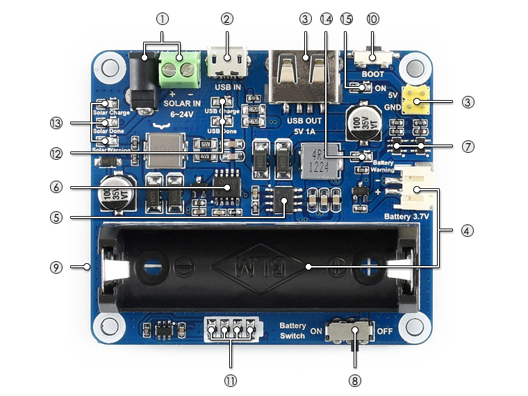
- Solar panel charging input: charged by solar panel, DC-002 jack or screw terminal
- USB charging input: charged by USB connection, connect a 5V power adapter through the Micro USB port
- 5V/1A power output: provides regulated 5V/1A output, USB port or 2.54mm pinheader
- Battery interfaces: for connecting 3.7V Li battery, Pstrong.0 connector or 14500 battery holder
- CS8501: USB power management chip, for USB charging and 5V/1A boost output
- CN3791: solar power management chip, for solar panel charging and buck input
- Li battery protection chip: Li battery over charge / over discharge protection
- Battery switch
- MPPTSET switch (bottom side):
supported level: 6V/9V/12V/18V/24V
select the level closed to input level to improve charging efficiency - BOOT key
- Battery capacity indicators
- USB charging indicators:
USB Charge: on when USB charging
USB Done: on when the battery is full charged by USB - Solar panel charging indicators:
Solar Charge: on when solar panel charging
Solar Done: on when the battery is full charged by solar panel
Solar Warning: on when solar panel reverse connection - Battery warning: on when battery reverse connection
- Power output indicator: 5V/1A output
 Dimensions
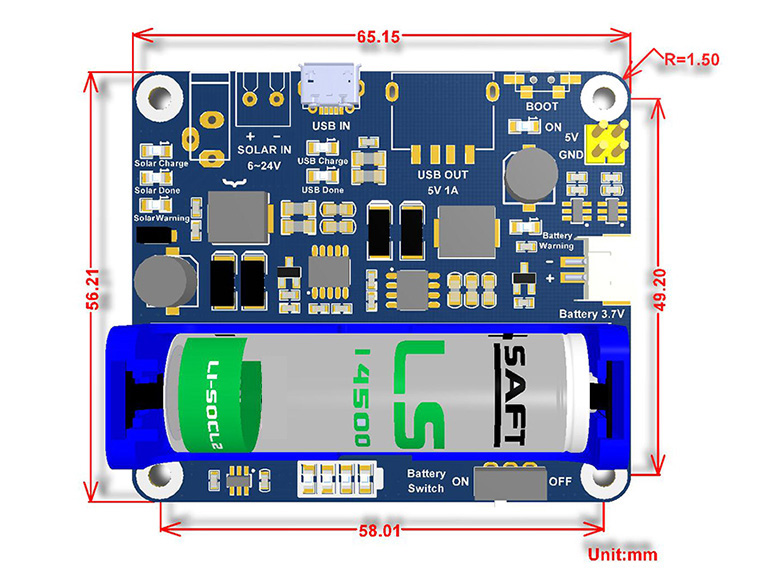 What's in the box?
1 x Solar Power Management Module
You might also need....
Applicable solar panel: Solar Panel (6V 5W) or Solar panel 18V 10W
Need batteries? You will find our battery selection here
Resources

25mm C-mount Telephoto lens for Raspberry Pi High Quality Camera
25mm focal length high definition telephoto lens, capturing every tiny details
Brings the beautiful world into your vision
Fitting the lens to Raspberry Pi High Quality Camera 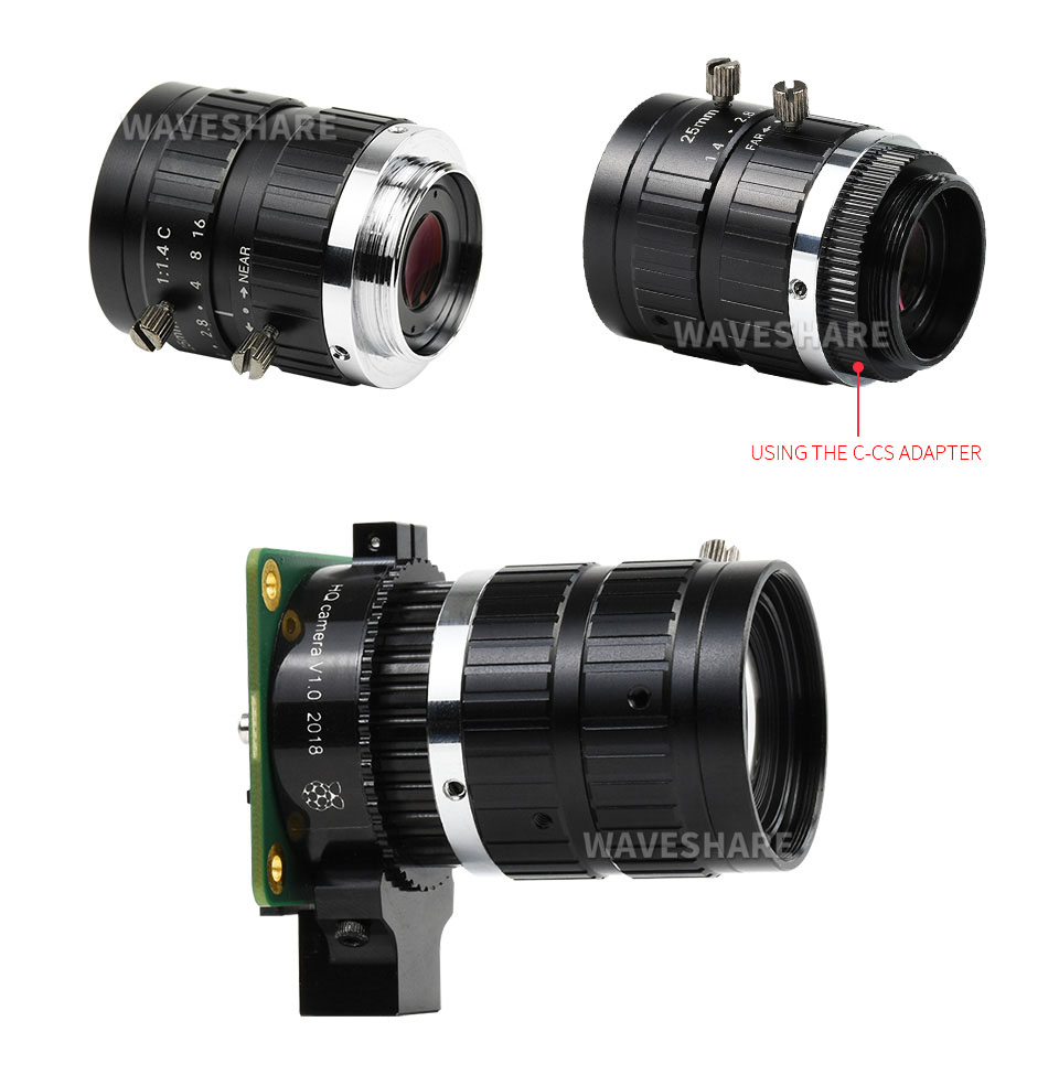
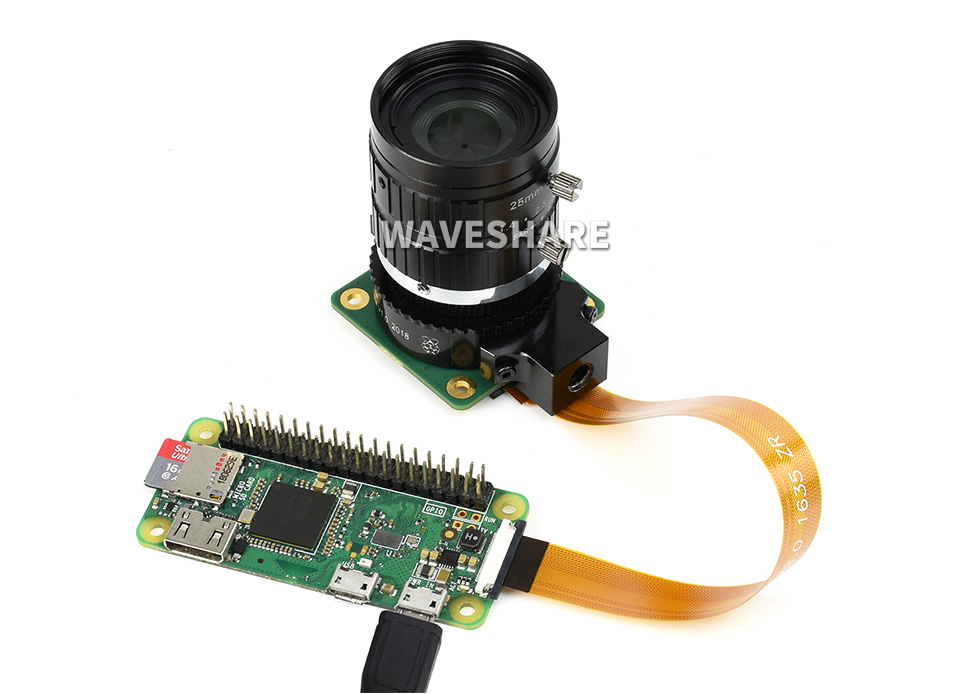
Working with Raspberry Pi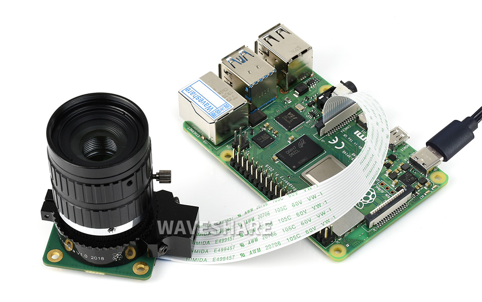
- Raspberry Pi, and High Quality Camera in the photos are NOT included
- To use with Raspberry Pi Zero, you need to buy an additional Raspberry Pi Zero v1.3 Camera Cable
What's in the box?
1 x 25mm lens
Resources

35mm C-mount Telephoto lens for Raspberry Pi High Quality Camera
35mm focal length high definition telephoto lens, capturing every tiny details
Brings the beautiful world into your vision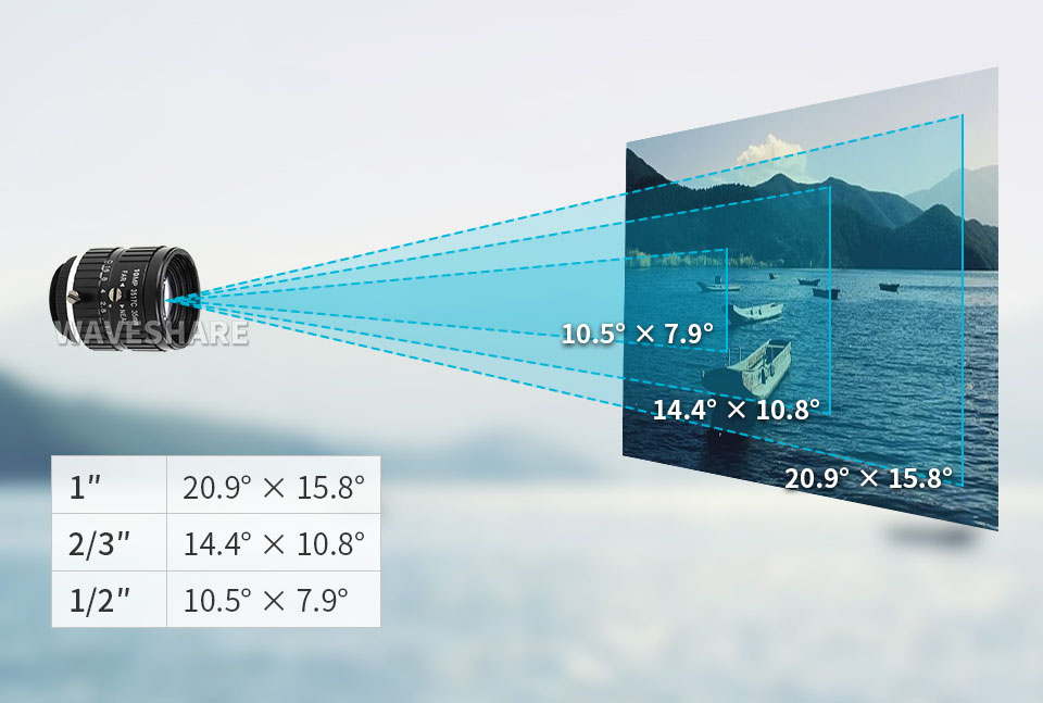
Fitting the lens to Raspberry Pi High Quality Camera 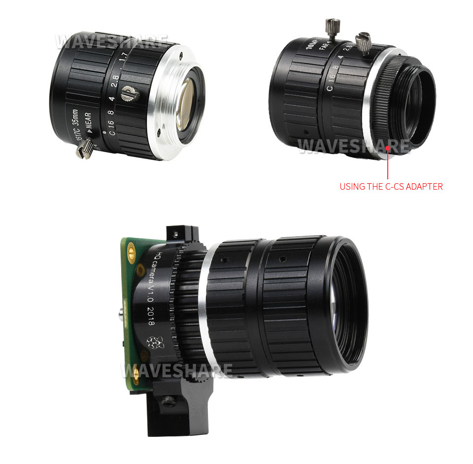
Working with Raspberry Pi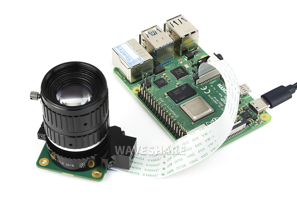
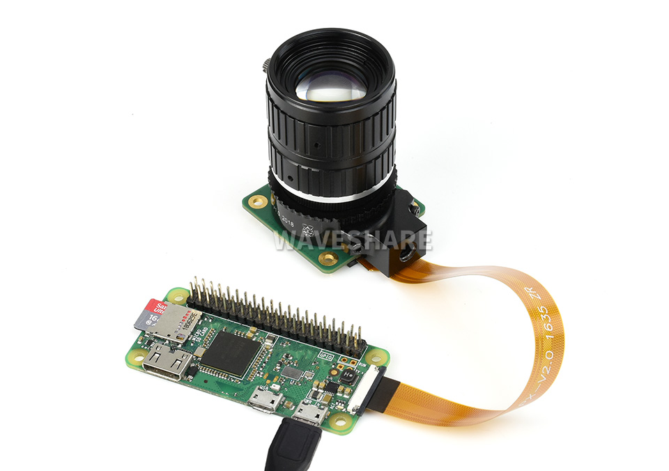
- Raspberry Pi, and High Quality Camera in the photos are NOT included
- To use with Raspberry Pi Zero, you need to buy an additional Raspberry Pi Zero v1.3 Camera Cable

This is a 4-ch current and power monitor HAT designed for Raspberry Pi. Via the I2C or SMBus interface, it is easy to monitor each channel's current, voltage, and power consumption, as well as the voltage between both sides of the sampling resistor.
- Standard Raspberry Pi 40PIN GPIO extension header, supports Raspberry Pi series boards
- 4-ch monitoring, via I2C/SMBus interface
- Onboard 0.1Ω 1% sampling resistor, allows measuring bi-directional current up to 3.2A
- Embedded 12-bit ADC, supports multiple successive converting, 0~26V voltage measuring range
- Directly calculate and output measured power value through additional multiply register
- I2C control pins for connecting with other host boards
- Comes with development resources and manual (examples for Raspberry Pi/Arduino/STM32)
Specifications
- Operating voltage: 3.3V/5V
- Control interface: I2C/SMBus
- Sampling resistor: 0.1Ω 1%
- Voltage range: 0~26V
- Current range: ±3.2A
- Resolution: 0.8mA (±3.2A range) OR 0.1mA (±400mA range)
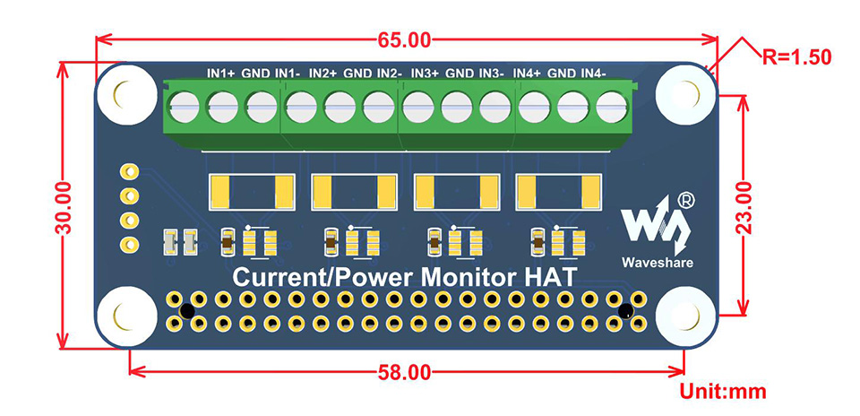
- Dimensions: 65mm × 30mm
- Mounting hole size: 3.0mm
Dimensions
What's in the box?
1 x Current/Voltage/Power Monitor HAT
Resources

*images are for reference only, RPi400/500 and expansion boards are NOT included.
If you are looking for easier, more visible connection to you Raspberry Pi 400/500? Looking to add a HAT or other add ons? This expansion board has enough place for both with 2 full sets of GPIO pins at your disposal.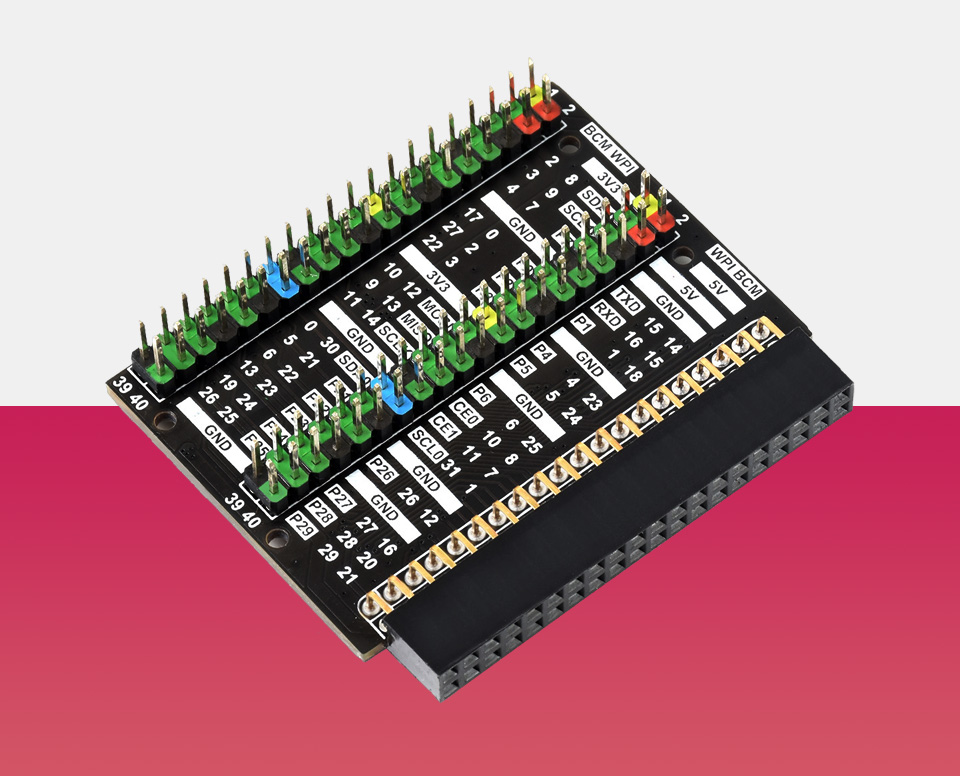
Colour-coded header, easy expansion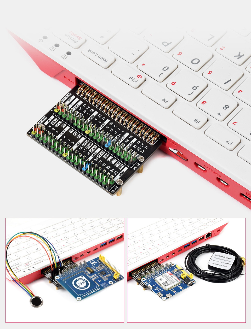
Outline Dimensions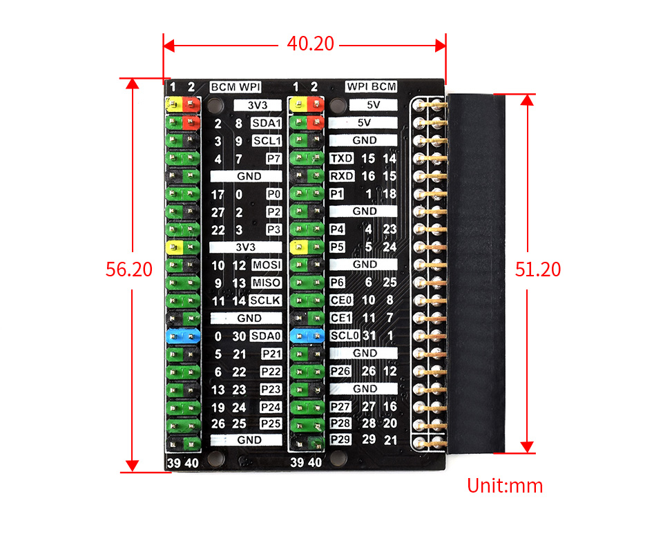
What's in the box?
1 x pi400/500 GPIO board

- POE: integrates 802.3af-compliant PoE circuit (5V/2.5A)
- USB: 4x USB 3.2 Gen1 portsMicro USB port
- Ethernet: Gigabit Ethernet RJ45 with PoE support
- Header: Color-coded 40PIN GPIO header
- Fan: 5V / 12V standard fan connector
- Power Input: 7V~36V
- CM4 Socket: suitable for all variants of Compute Module 4
- RTC: Real-time clock with battery socket and ability to wake Compute Module 4
- Video: 2x MIPI DSI display FPC connectors (22-pin 0.5 mm pitch cable)
- Camera: 2x MIPI CSI-2 camera FPC connectors (22-pin 0.5 mm pitch cable)
- SD card slot: MicroSD card socket for Compute Module 4 Lite (without eMMC) variants
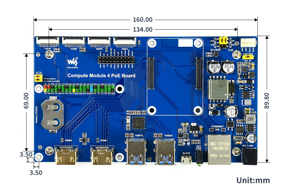
- Dimensions: 160 × 90mm
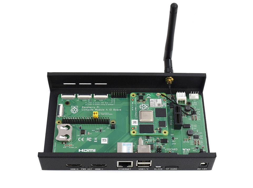
Standard CM4 socket and color-coded Raspberry Pi 40PIN GPIO header suitable for all variants of Compute Module 4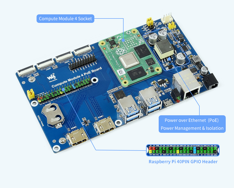
Onboard connectors including CSI/DSI/RTC/HDMI/USB/ETH/TF card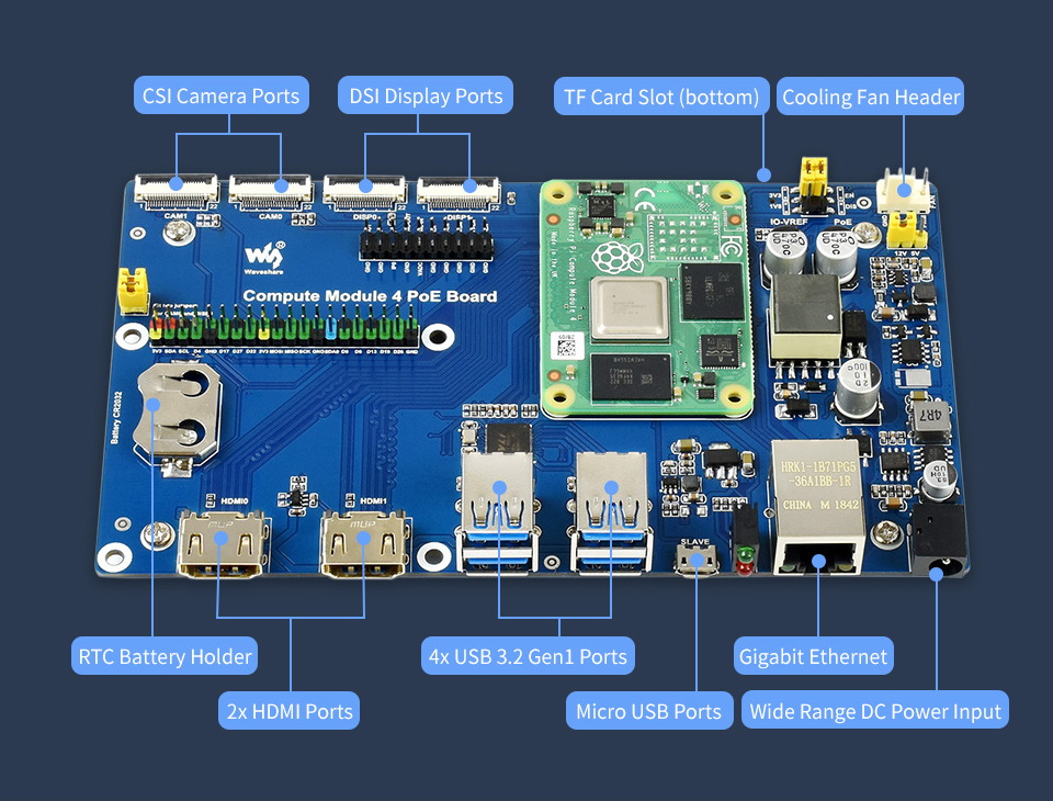
What's On Board?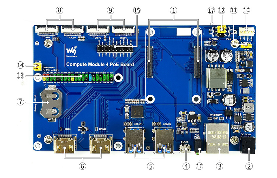
- CM4 socket: suitable for all variants of Compute Module 4
- Power input: 7~36V wide range power supply
- Gigabit Ethernet connector: Gigabit Ethernet RJ45 with PoE support
- USB SLAVE port: allows burning system image into Compute Module 4 eMMC variants
- USB3.2 ports: 4x USB 3.2 Gen1 ports, for connecting sorts of USB devices
- HDMI ports: 2x HDMI ports, supports dual 4K 30fps output
- RTC: RTC battery holder, allows RTC-related functions like wakeup, shutdown, reboot, and more
- CAM: 2x MIPI CSI camera ports
- DISP: 2x MIPI DSI display port
- FAN: for connecting cooling fan, allows speed adjustment and measurement
- FAN power selection: 5V or 12V voltage to drive the fan
- IO-VREF/PoE selection: CM4 IO logic level: 3.3V or 1.8V
PoE: enable (EN) or disable (DIS) - 40PIN GPIO header
- CAM0 and DISP0 I2C bus: fit the jumpers when using CAM0 or DISP0
- Misc configurations
- Dual LED indicators: red: Raspberry Pi power indicator, green: Raspberry Pi operating status indicator
- TF card slot (bottom side): insert a Micro SD card with pre-burnt system, to start up Compute Module 4 Lite
Outline dimensions
What's in the box?
1 x Compute Module 4 PoE Board
Resources
WIKI: Compute_Module_4_PoE_Board

Recording and playback support, stereo codec, built-in microphone and speaker suitable for Raspberry Pi. Driver-free, Plug and Play.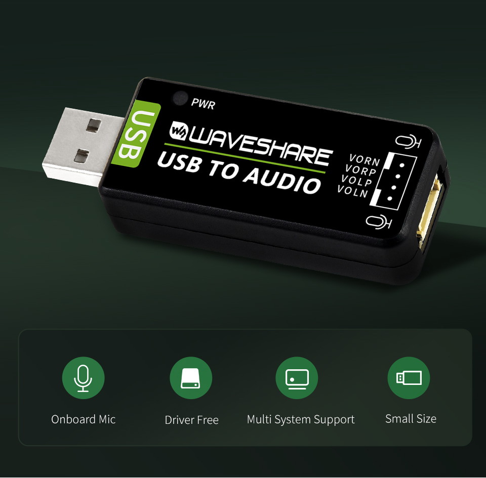
Built-in microphone and speaker, easy audio input / output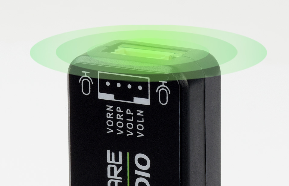
Supported sampling rates including 8K, 11.025K, 12K, 16K, 22.05K, 24K,
32K, 44.1K, and default 48K (Hz)

Power indicator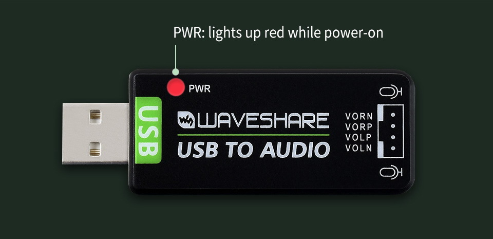
Look inside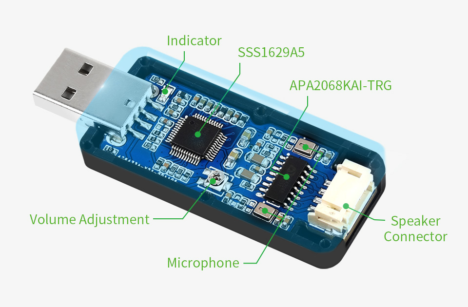
Standard USB 2.0 port, driver-free, portable size

Outline dimensions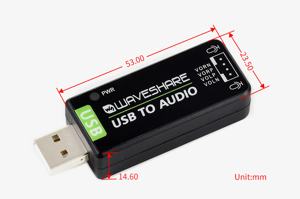
What's in the box?
1 x USB Sound Card
You might want to get some speakers for this dongle.
Resources
Support docs

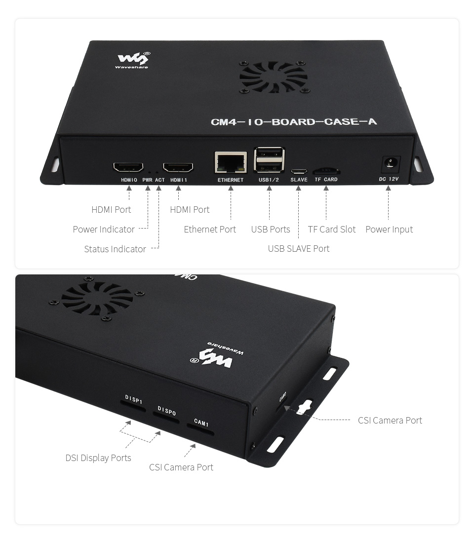
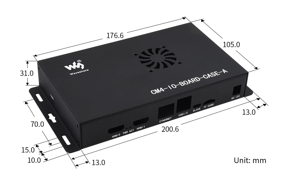
Fits the Raspberry Pi Compute Module 4 IO Board
- Designed for Raspberry Pi Compute Module 4 IO Board
- Mini computer chassis, robust and dust-proof, professional look
- Make it easy to build your own Raspberry Pi CM4 mini PC
- Precise cut-out with clear label
- Each cut-out is completely aligned with the connector
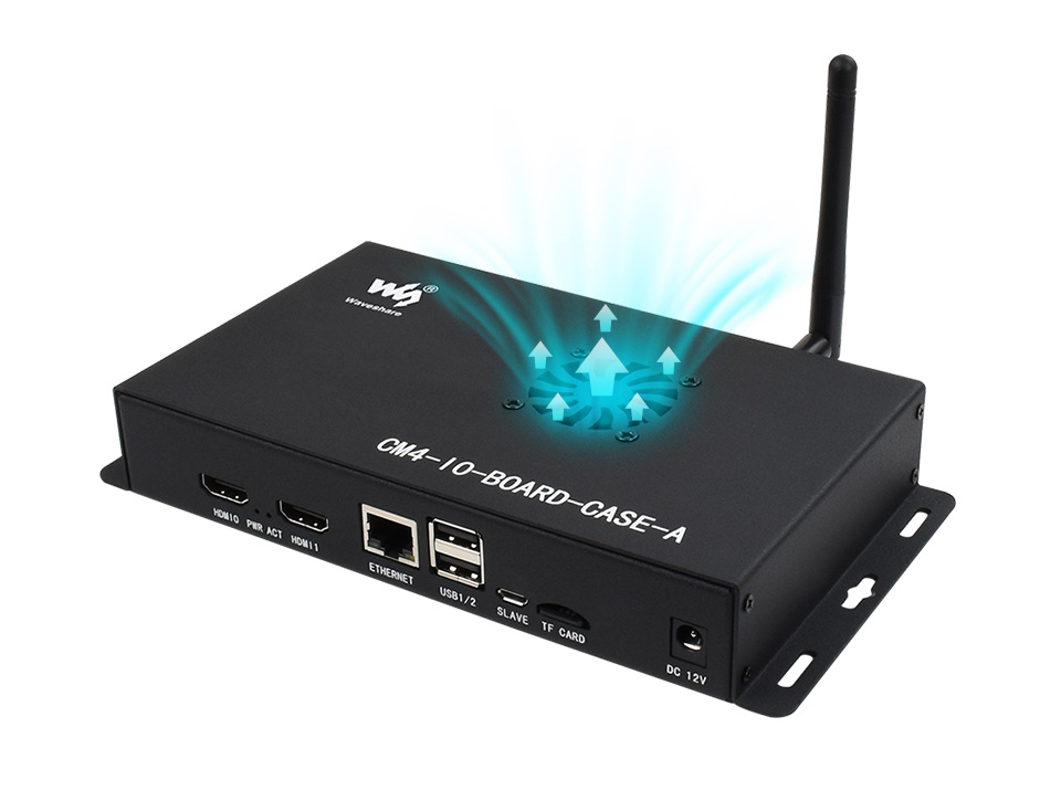
Comes with cooling fan, combined with the airflow vent, better heat dissipation
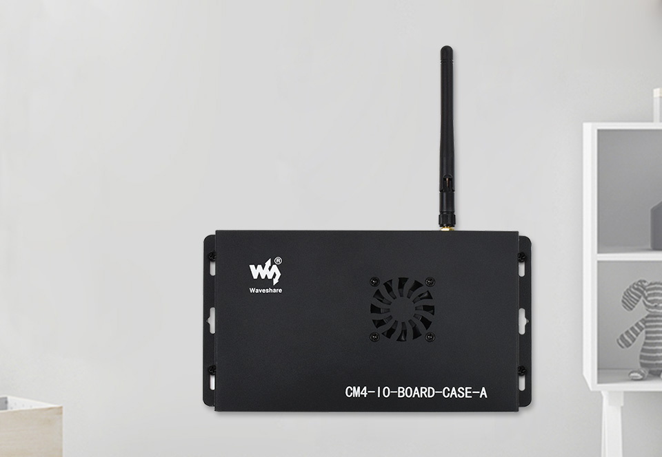
Wall mount support on two sides
Outline dimensions
What's in the box?
1 x Metal Case (A) for Raspberry Pi CM4 IO Board

- Standard Raspberry Pi Pico header, supports Raspberry Pi Pico series
- Onboard high precision RTC chip DS3231, with backup battery holder
- Real-Time Clock Counts Seconds, Minutes, Hours, Date of the Month, Month, Day of the Week, and Year with Leap-Year Compensation Valid Up to 2100
- Optional format : 24-hour OR 12-hour with an AM/PM indicator
- 2x programmable alarm clock
- Comes with development resources and manual (Raspberry Pi Pico C/C and MicroPython examples)
Specifications
| Operating voltage | 3.3V |
|---|---|
| Backup battery voltage | 2.3V ~ 5.5V |
| Operating temperature | -40°C ~ 85°C |
| Power consumption | 100nA (sustains data and clock information) |
Raspberry Pi Pico header compatibility
Onboard female pin header for direct attaching to Raspberry Pi Pico Stackable design
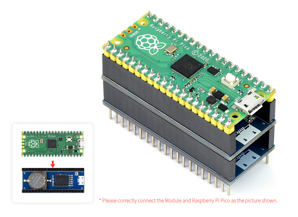
Raspberry Pi Pico is NOT included.
What's On Board
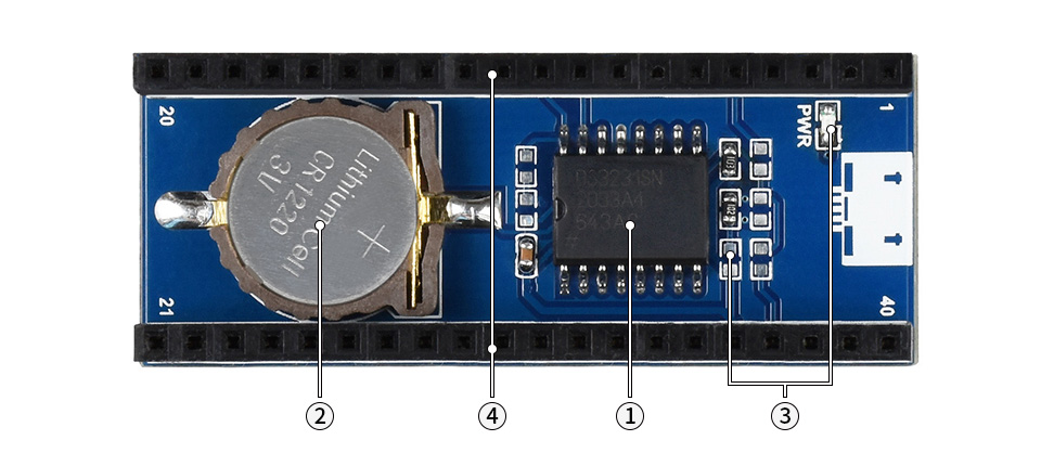
- DS3231 - high precision RTC chip, I2C bus
- RTC backup battery - supports CR1220 button cell
- Power indicator - enabled by soldering a 0Ω resistor on the jumper, disabled by default
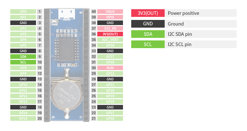
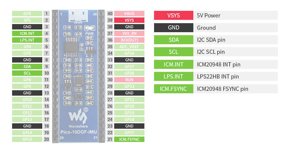
Pinout definition
Outline dimensions
What's in the box?
1 x RTC Module for Raspberry Pi Pico
Resources

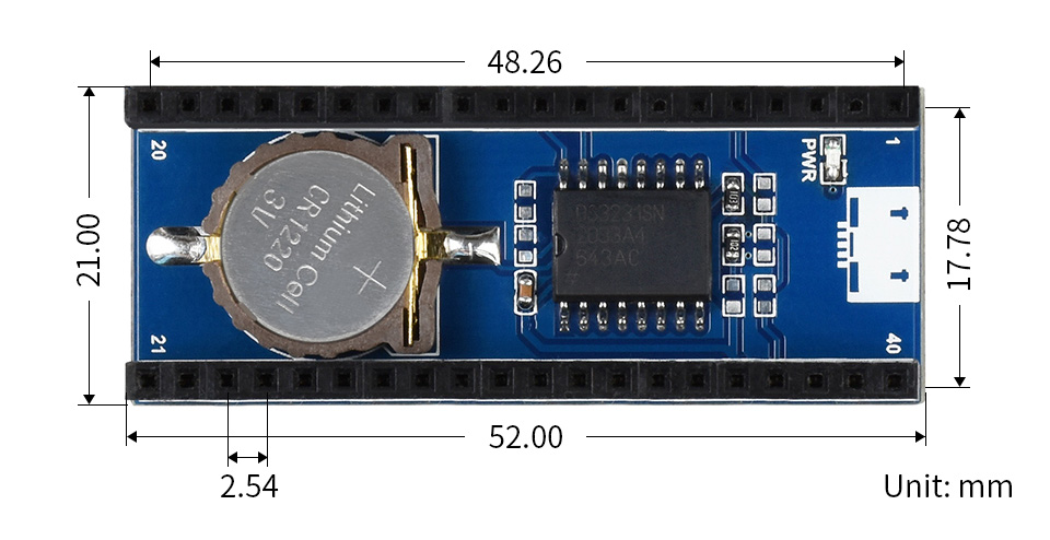
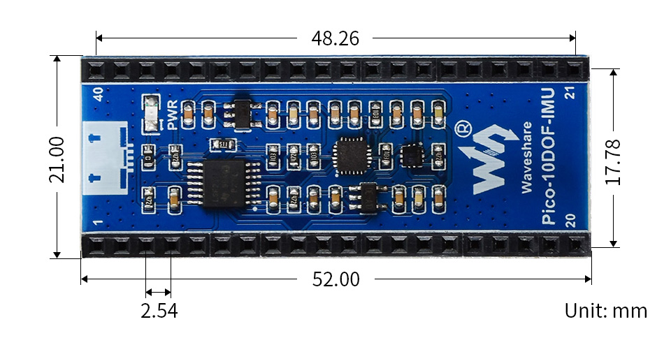
The Pico-10DOF-IMU is an IMU sensor expansion module specialized for Raspberry Pi Pico. It incorporates sensors including gyroscope, accelerometer, magnetometer, baroceptor, and uses I2C bus for communication.
Combined with the Raspberry Pi Pico, it can be used to collect environment sensing data like temperature and barometric pressure, or to easily DIY a robot that detects motion gesture and orientation.
- Standard Raspberry Pi Pico header, supports Raspberry Pi Pico series
- Onboard MPU9250 (3-axis gyroscope, 3-axis accelerometer, and 3-axis magnetometer) for detecting motion gesture, orientation, and magnetic field
- Onboard LPS22HB barometric pressure sensor, for sensing the atmospheric pressure of the environment
- Comes with development resources and manual (Raspberry Pi Pico C/C and MicroPython examples)
| Operating voltage | 5V |
|---|---|
| accelerometer | resolution: 16-bit measuring range (configurable): ±2, ±4, ±8, ±16g operating current: 68.9uA |
| gyroscope | resolution: 16-bit measuring range (configurable): ±250, ±500, ±1000, ±2000°/sec operating current: 1.23mA |
| magnetometer | resolution: 16-bit measuring range: ±4900µT operating current: 90uA |
| baroceptor | measuring range: 260 ~ 1260hPa measuring accuracy (ordinary temperature): ±0.025hPa measuring speed: 1Hz - 75Hz |
Raspberry Pi Pico header compatibility
Onboard female pin header for direct attaching to Raspberry Pi Pico
Stackable design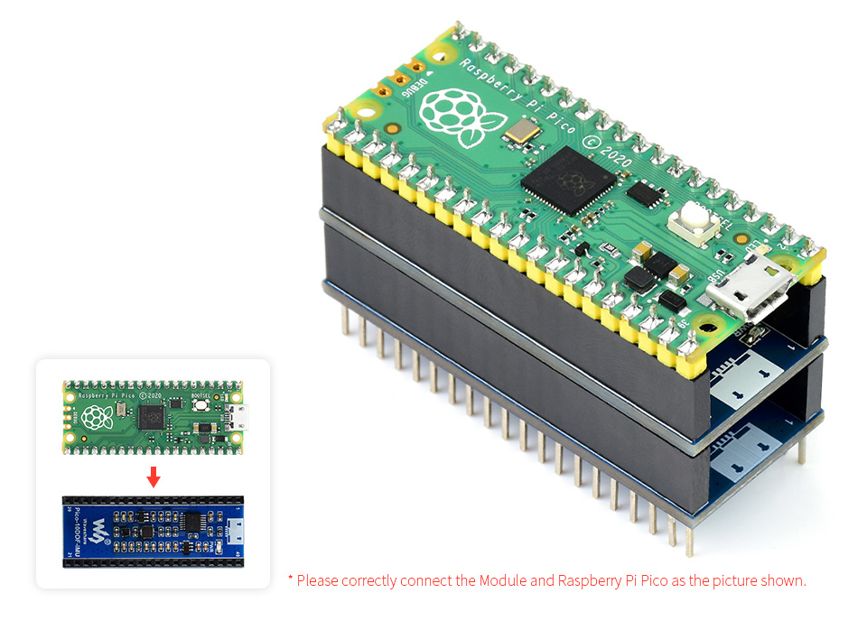
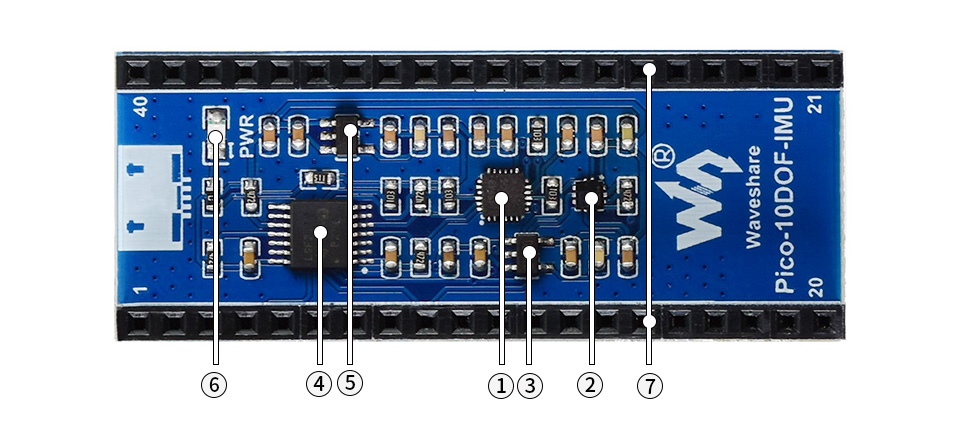
- MPU9250
9-axis motion sensor, I2C bus - LPS22HB
barometric pressure sensor, I2C bus - RT9193-33
3.3V linear voltage regulator - LSF0204PWR
4-ch voltage translator
- RT9193-18
1.8V linear voltage regulator - Power indicator
- Raspberry Pi Pico header
for attaching to Raspberry Pi Pico, stackable design
Outline dimensions
What's in the box?
1 x 10-DOF IMU Sensor Module for Raspberry Pi Pico
Raspberry Pi Pico is NOT included.
Resources & Services

This LCD accepts 8-bits/9-bits/16-bits/18-bits parallel interface, that are RGB444, RGB565, RGB666. The color format used in demo codes is RGB565.
This LCD uses a 4-line SPI interface for reducing GPIO and fast speed.LCD
Features at a glance
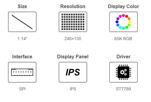
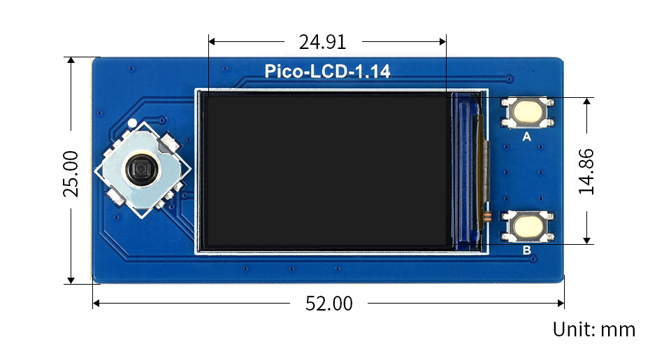
- 240×135 resolution, IPS screen, 65K RGB colors, clear and colorful displaying effect
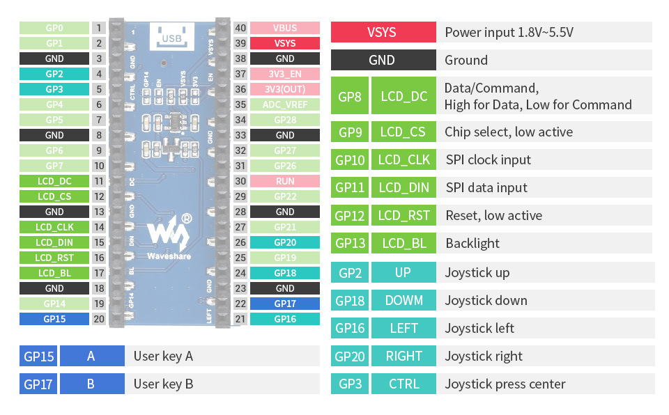
- SPI interface, requires minimal IO pins
- 1x joystick and 2x user buttons for easy interacting
- Comes with development resources and manual (Raspberry Pi Pico C/C and MicroPython examples)
Specifications
| Operating voltage | 2.6 ~ 5.5V | Resolution | 240×135 pixels |
|---|---|---|---|
| Communication Interface | 4-wire SPI | Display size | 24.91 × 14.86mm |
| Display Panel | IPS | Pixel size | 0.1101 × 0.1035mm |
| Driver | ST7789 | Dimensions | 52.00 × 25.00mm |
Raspberry Pi Pico header compatibility
- Onboard female pin header for direct attaching to Raspberry Pi Pico
- 1x joystick and 2x user buttons for easy interacting
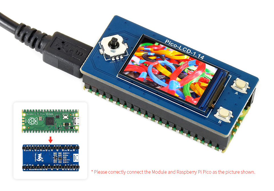
Raspberry Pi Pico is NOT included.
Pinout definition
Outline dimensions
What's in the box?
1 x 1.14inch LCD Display Module for Raspberry Pi Pico
Resources

- No backlight, keeps displaying last content for a long time even when power down
- Ultra low power consumption, basically power is only required for refreshing
- SPI interface, requires minimal IO pins
- Comes with development resources and manual (Raspberry Pi Pico C/C and MicroPython examples)
Specifications
| operating voltage | 3.3V/5V | grey scale | 2 |
|---|---|---|---|
| interface | 3-wire SPI, 4-wire SPI | partial refresh time | 0.3s |
| outline dimensions | 65.00 × 30.50mm | full refresh time | 2s |
| display size | 48.55 × 23.70mm | refresh power | 26.4mW(typ.) |
| dot pitch | 0.194 × 0.194mm | standby current | <0.01uA (almost none) |
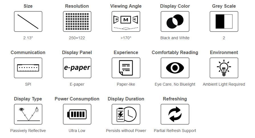
| resolution | 250×122 pixels | viewing angle | >170° |
| display color | black, white |
Advantages of EINK
E-paper display utilizes microcapsule electrophoretic technology for displaying, the principle is: charged particles suspended in clear fluid will move to sides of microcapsule when electric field is applied, making the microcapsule become visible by reflecting ambient light, just as traditional printed paper.
E-paper display will clearly display images/texts under lamplight or natural light, requires no backlight, and features nearly up to 180° viewing angle. It is usually used as e-reader due to its paper-like effect.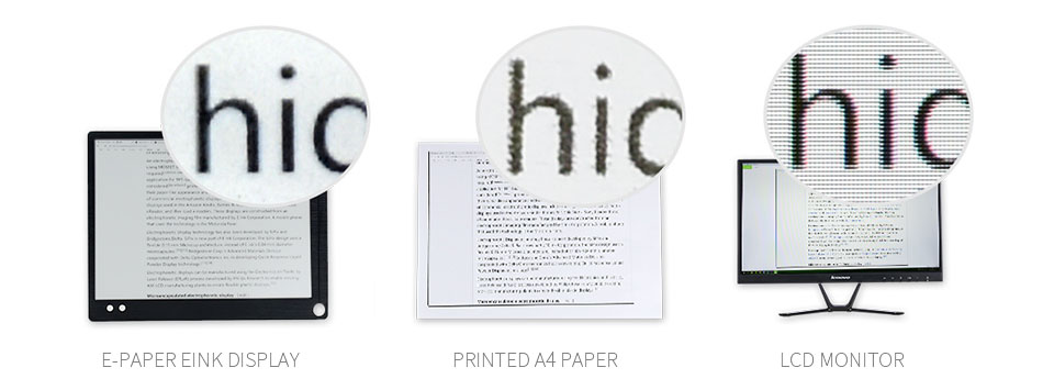
Onboard female pin header for direct attaching to Raspberry Pi Pico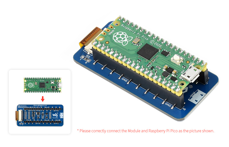
Raspberry Pi Pico is NOT included.
Suitable for price Tags, asset/equipment Tags, shelf labels, conference name tags...
Pinout definition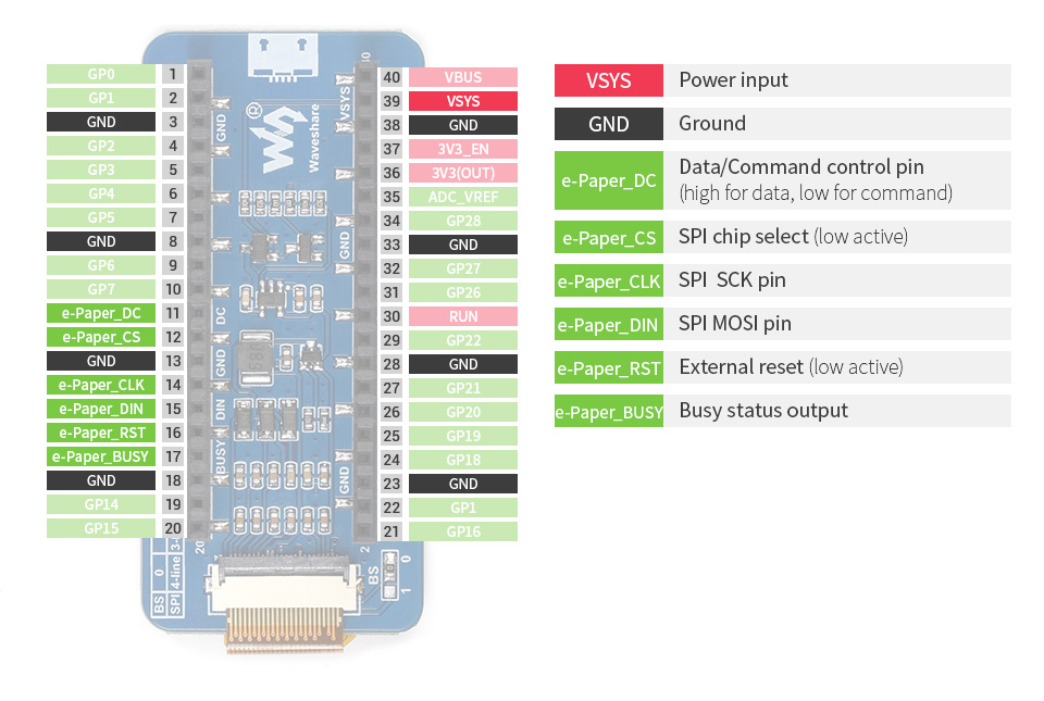
Outline dimensions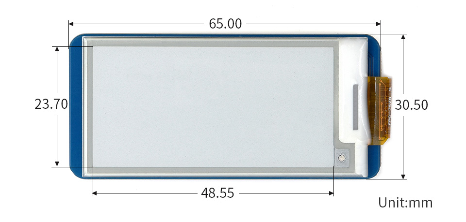
What's in the box?
1 x pico e-paper display 250x122
Resources

Features at a glance
- Standard Raspberry Pi Pico female header for direct attaching Raspberry Pi Pico (if male header soldered), or just through jumper wires
- Two sets of 2x20 male header, allows connecting more Raspberry Pi Pico expansion modules
- Clear pinout labels on the front side, easy to use
- Immersion gold process, beautiful & practical, stunning aesthetic looking
Raspberry Pi Pico header compatibility
Center female pin header for direct attaching the Raspberry Pi Pico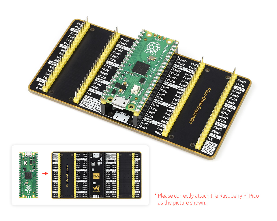
Allows connecting more Raspberry Pi Pico expansion modules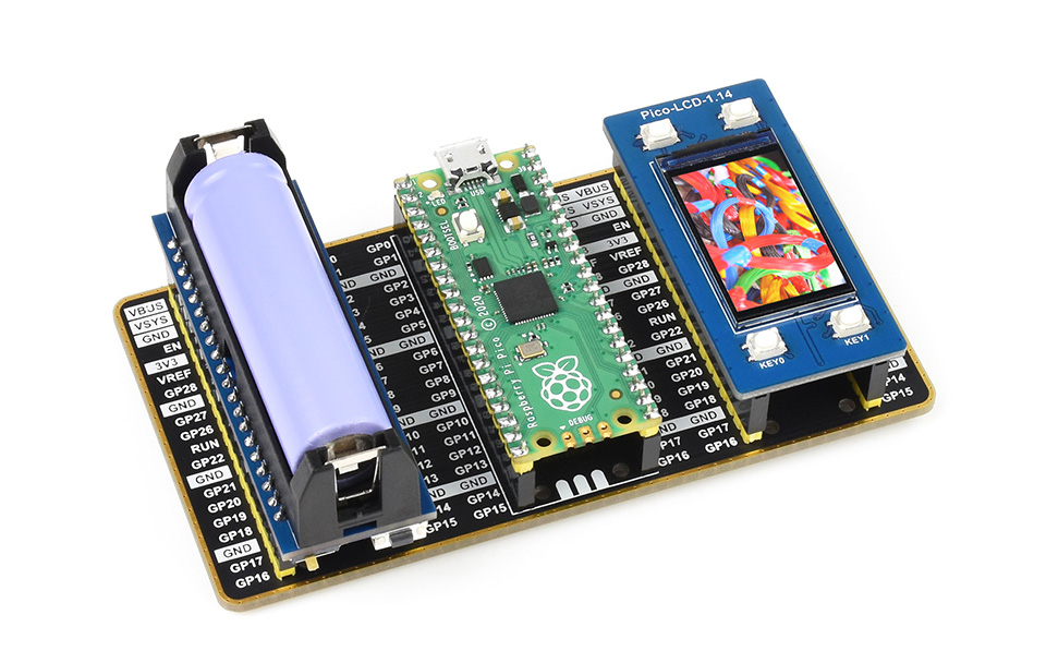
Raspberry Pi Pico and expansion modules are NOT included.
Immersion gold process
Black base panel, white pinout labels, golden rounded outline, stunning aesthetic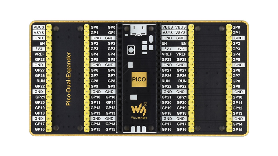
Outline dimensions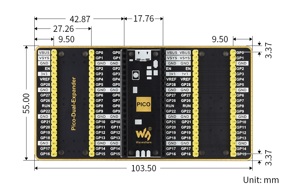
What's in the box?
1 x Dual GPIO Expander

- Standard Raspberry Pi Pico female header for direct attaching Raspberry Pi Pico (if male header soldered), or just through jumper wires
- Four sets of 2x20 male header, allows connecting more Raspberry Pi Pico expansion modules
- USB power input connector, ensures sufficient power supply for multiple expansion modules
- Clear pinout labels on the front side, easy to use
- Immersion gold process, beautiful & practical, stunning aesthetic looking
Center female pin header for direct attaching the Raspberry Pi Pico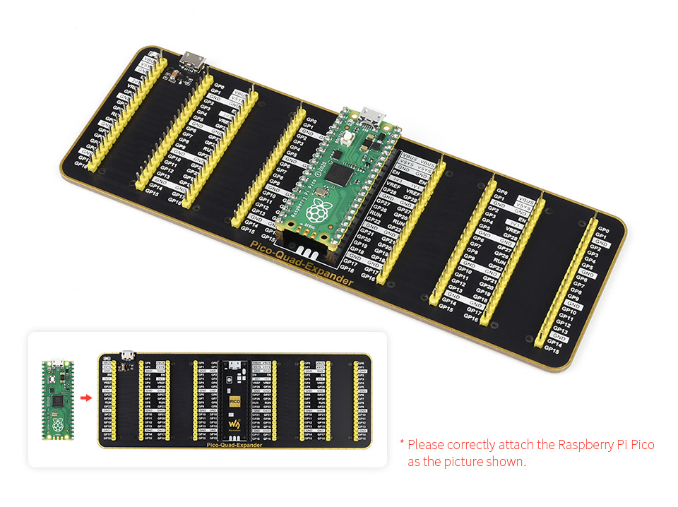
Allows connecting more Raspberry Pi Pico expansion modules
Extra USB connector for external power supply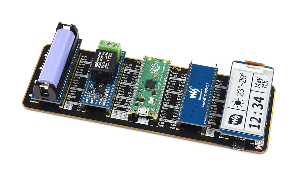
Raspberry Pi Pico and expansion modules are NOT included.
Black base panel, white pinout labels, golden rounded outline, stunning aesthetic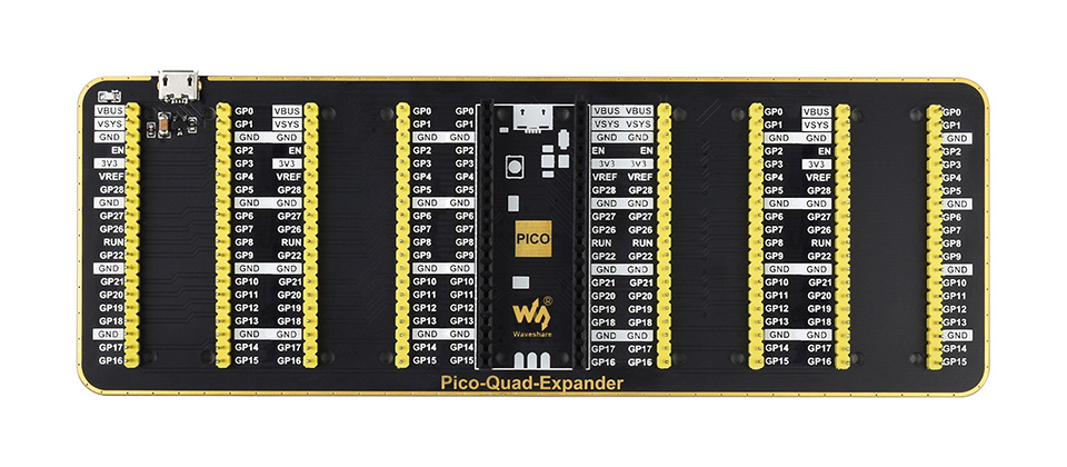
Outline dimensions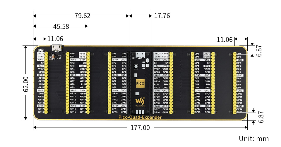
What's in the box?
1 x Pico expander board

B1/B3/B5/B8/B20/B28 frequency band
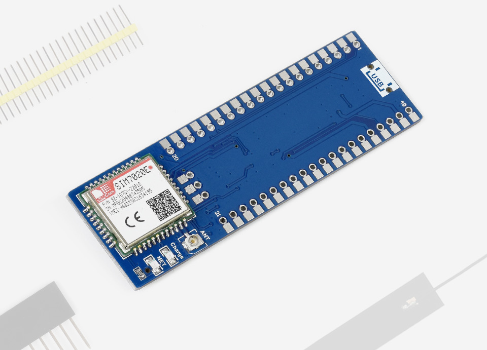
The Pico-SIM7020E-NB-IoT is an NB-IoT (NarrowBand-Internet of Things) module designed for Raspberry Pi Pico. It supports multiple NB-IoT frequency band, can be controlled via serial AT commands, and supports communication protocols like HTTP/MQTT/LWM2M/COAP, etc. Due to the advantages of low delay, low power, low cost, and wide coverage, it is the ideal choice for IoT applications such as intelligent instruments, asset tracking, remote monitoring, and so on.
- Standard Raspberry Pi Pico header, supports Raspberry Pi Pico series boards
- UART communication, serial AT commands control, multiple communication protocols support, multiple cloud platform support
- Integrates 3.7V Li-po battery connector and recharge circuit, allows being powered from external rechargeable Li-po battery, or recharging it in turn
- 2x LED indicators, for monitoring the module operating status
- Onboard Nano SIM card slot for NB-IoT specific card
- Comes with development resources and manual (MicroPython examples)
Specifications
| Communication | |
|---|---|
| Frequency band | LTE-FDD: B1/B3/B5/B8/B20/B28 |
| Data rate | 26.15kbps (DL) / 62.5kbps (UL) |
| Communication interface | UART |
| Baudrate | 300bps~921600bps (115200bps by default) |
| Communication Protocol | TCP/UDP/HTTP/HTTPS/MQTT/LWM2M/COAP/TLS/DTLS/DNS/NTP |
| Applicable region | Asia, Europe, Africa, Australia |
| Operating | |
| Power supply | External Li-po battery OR Raspberry Pi Pico USB port |
| Battery interface | 3.7V ~ 4.2V |
| Logical level | 3.3V |
| Module standalone current | Idle mode: 5.6mA Sleep mode: 0.4mA PSM mode: 3.4uA |
| Dimensions | 73.5 × 24.00mm |
Raspberry Pi Pico header compatibility
the Pico can be SMD-mounted (left), or attached via female header (right)
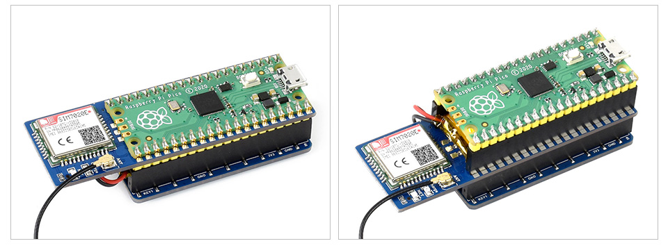
connecting with other expansion module and antenna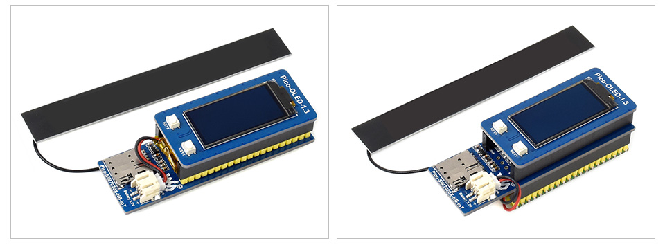
Raspberry Pi Pico and other boards shown are NOT included.
The pin headers are NOT soldered by default.
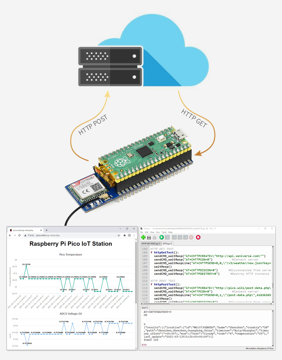
Supports communication protocols including: TCP/UDP/HTTP/HTTPS/MQTT/LWM2M/COAP/TLS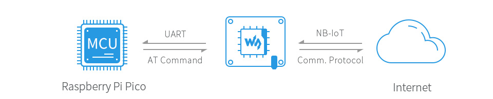
Pinout definition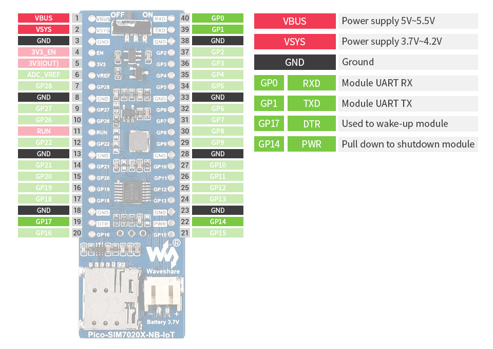
Outline dimensions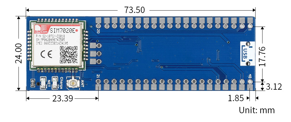
What's in the box?
1 x IoT Module For Raspberry Pi Pico
Resources

Connection Examples
Working with Raspberry Pi 4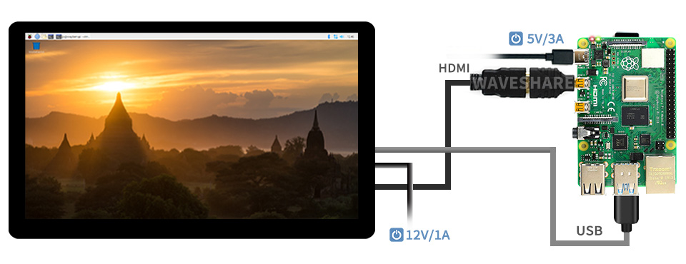
Working with Raspberry Pi Zero W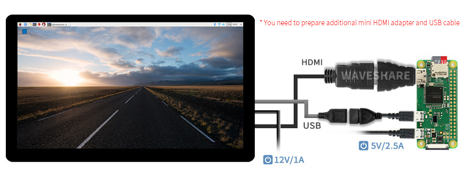
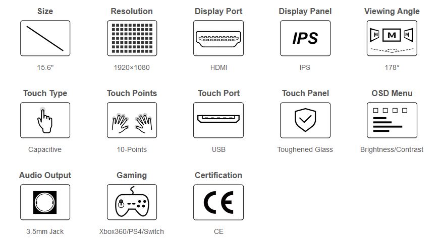
IPS Panel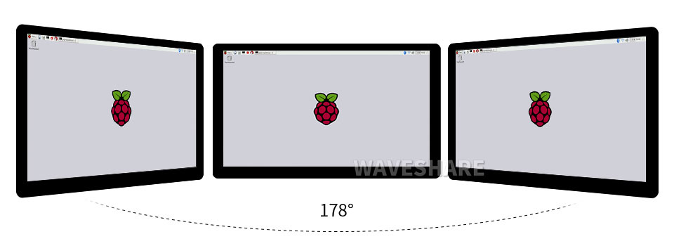
Touch Control
Appearance and Dimensions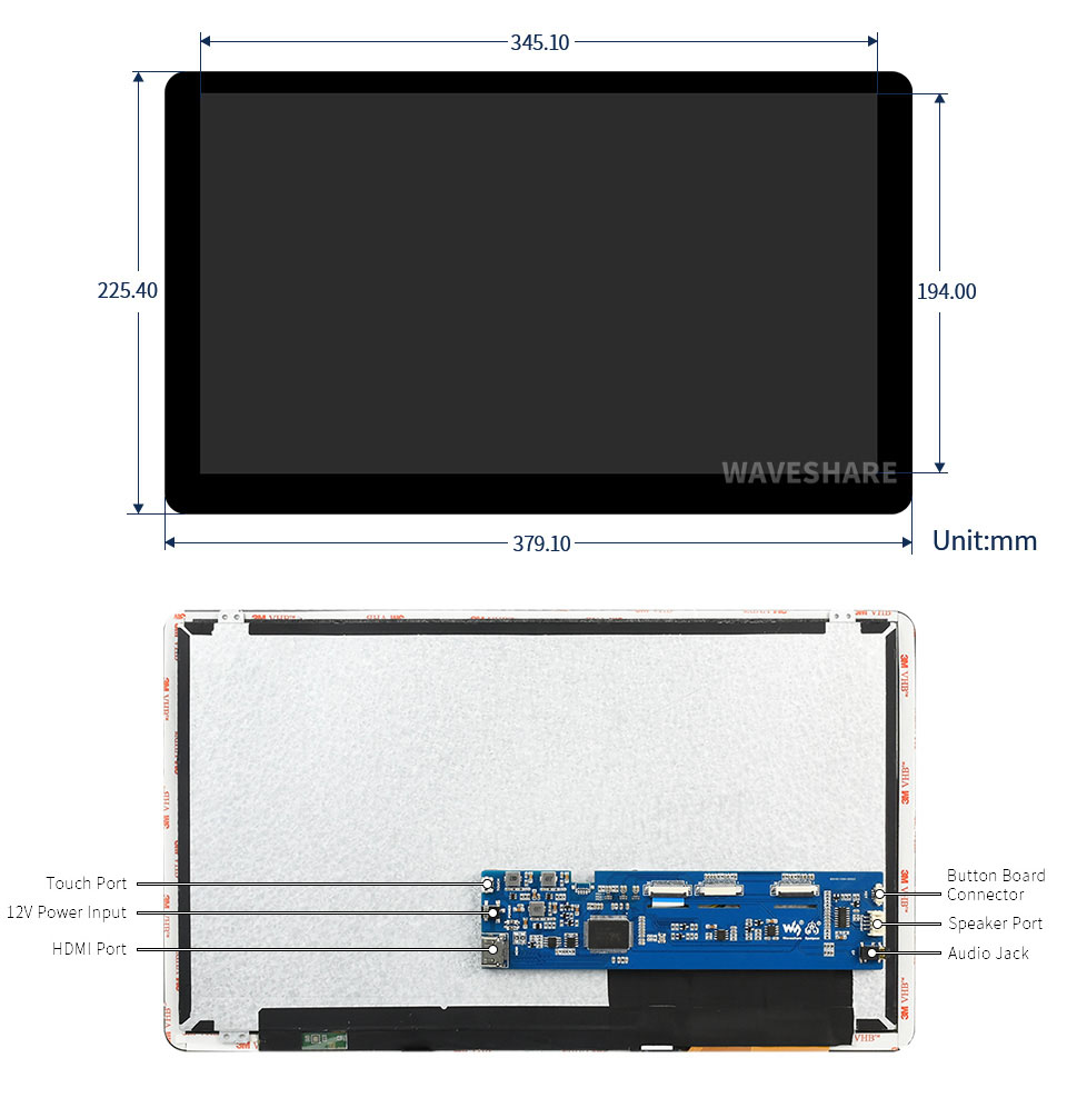
What's in the box?
1 x 15.6inch touch display
1 x Power adapter 12V
1 x HDMI cable
1 x HDMI to Micro HDMI Adapter
1 x USB-A to Micro-B cable
1 x Triangular stand
1 x Button board cable
1 x Button board
Resources

This board is ideal for controlling robotic arms or hexapod walkers
- Standard Raspberry Pi Pico header, supports Raspberry Pi Pico series boards
- Up to 16-Channel servo/PWM outputs, 16-bit resolution for each channel
- Integrates 5V regulator, up to 3A output current, allows battery power supply from the VIN terminal
- Standard servo interface, supports common used servo such as SG90, MG90S, MG996R, etc.
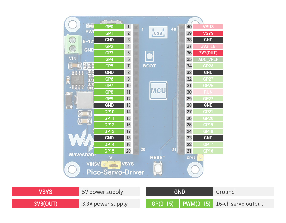
- Exposes unused pins of Pico, easy expansion
- Comes with development resources and manual (Raspberry Pi Pico C/C and MicroPython examples)
Specifications
| Operating voltage | 5V (Pico) or 6~12V (VIN terminal) | Servo voltage level | 5V |
|---|---|---|---|
| Logic level | 3.3V | Control interface | GPIO |
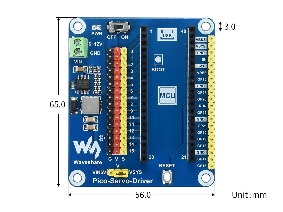
| Mounting hole size | 3.0mm | Dimensions | 65 × 56mm |
Raspberry Pi Pico header compatibility
onboard female pin header for direct attaching to Raspberry Pi Pico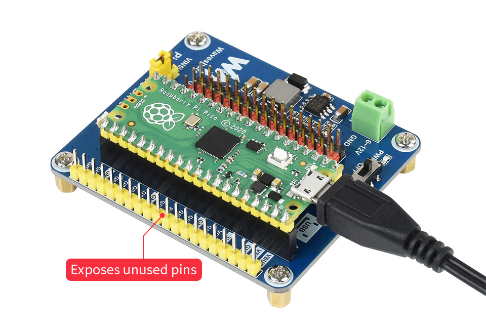
supports common used servo like: SG90, MG90S, MG996R 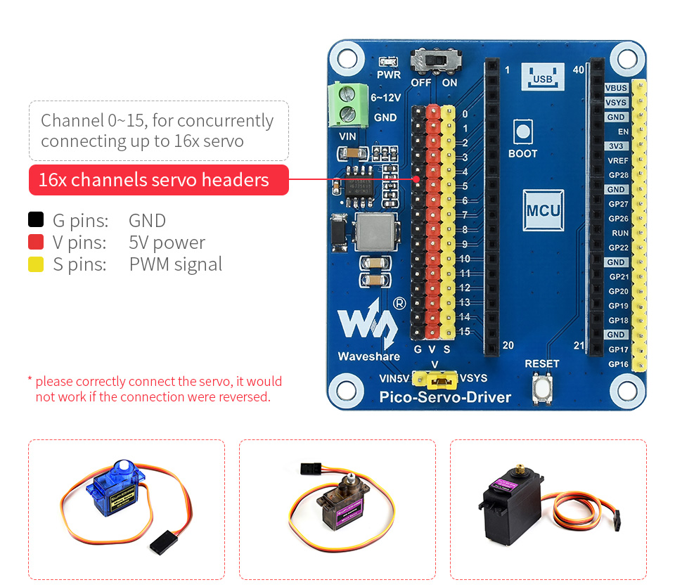
flexible power options: powered from Pico directly,
or from VIN battery input terminal with max 3A current output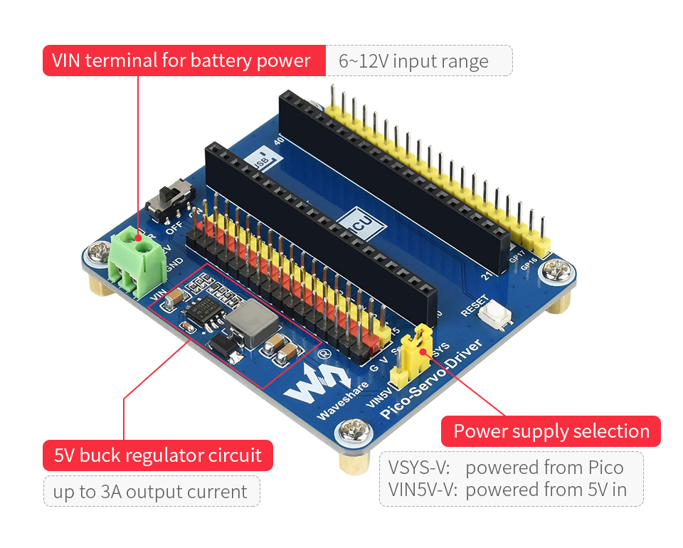
Application example
Outline dimensions
What's in the box?
1 x Pico servo controller board
Resources

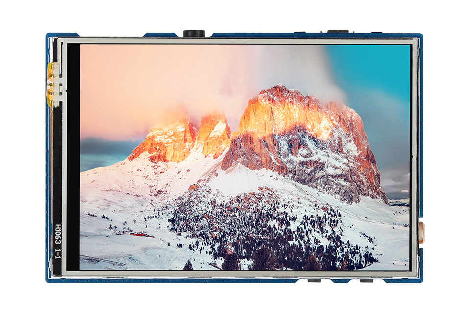
The Pico-Eval-Board is an overall evaluation solution designed for Raspberry Pi Pico.
The Pico-Eval-Board is an overall evaluation solution designed for Raspberry Pi Pico. With 3.5inch 65K colorful LCD display and misc helpful onboard components, this evaluation board allows you to try almost every on-chip peripheral of the RP2040, eliminating the messy wiring. It is an ideal choice for users to fast get started with the Raspberry Pi Pico, as well as the RP2040 chip.
Specifications
- Operating voltage: 5V
- Touch Type: Resistive
- Communication bus: SPI
- Display panel: IPS
- Controller: ILI9488/XPT2046
- Resolution: 480×320 Pixels
- Display colors: 65K colorful
- Pixel size: 0.153 × 0.153 mm
- Display size: 73.44 × 48.96 mm
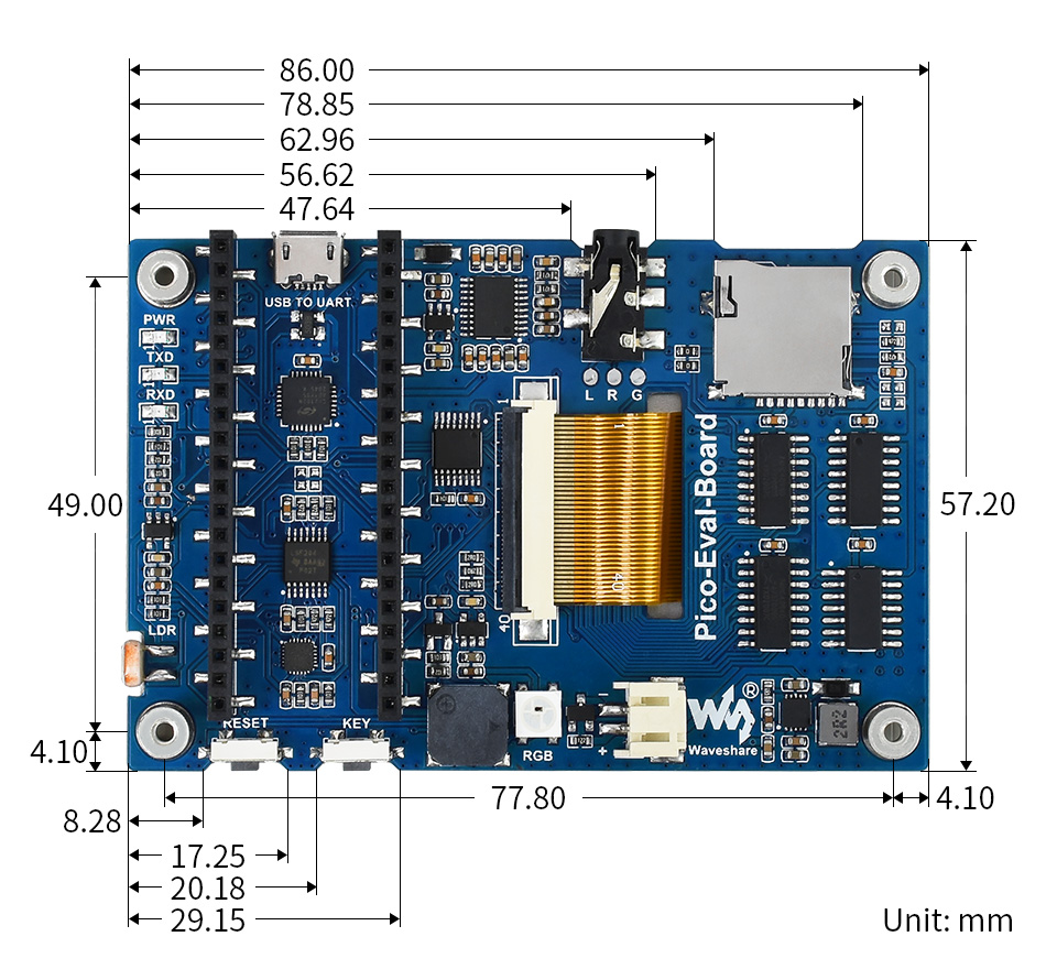
- Dimensions: 86.00 × 57.20 mm
Features
- Standard Raspberry Pi Pico header, supports Raspberry Pi Pico series boards
- 3.5inch resistive touch screen, 65K colorful, bringing clear and vivid display effect
- Standard 3.5mm audio jack, for headphone or other audio peripherals
- Micro SD card slot through the SDIO interface, faster access speed than SPI interface
- Integrates battery header and recharge circuit, allows it keep running without wired power supply
- Other rich resources like buzzer, photoresistor, and RGB LED.
- Comes with development resources and manual (Raspberry Pi Pico C/C and MicroPython examples)
What's in the box?
1 x Overall Evaluation Board for Raspberry Pi Pico
Resources
Wiki for Evaluation Board for Raspberry Pi Pico
With 3.5inch 65K colorful LCD display and misc helpful onboard components, this evaluation board allows you to try almost every on chip peripheral of the RP2040, eliminating the mess wiring.
It is an ideal choice for user to fast get started with the Raspberry Pi Pico, as well as the RP2040 chip.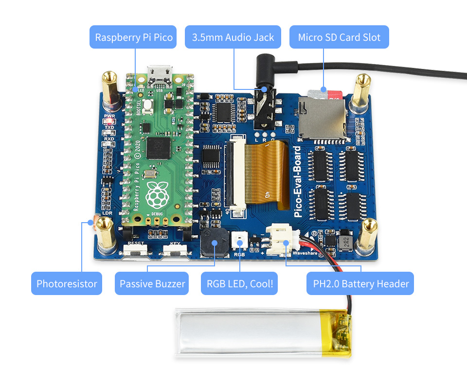

Specifications
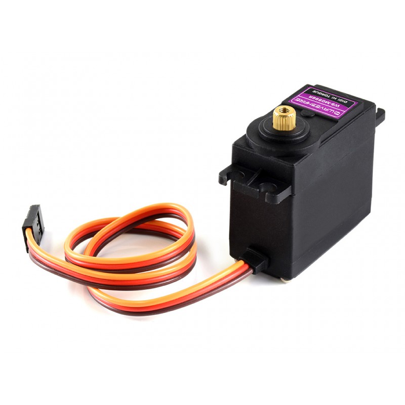
- Product: MG996R Servo
- Torque: 9kg/cm(4.8V), 11kg/cm(6V)
- Speed: 0.19s/60°(4.8V), 0.18s/60°(6V)
- Rotate angle: 180°
- Operating voltage: 4.8 ~ 6V
- Gear: metal
- Dead band: 5us
- Weight: 55g
- Dimension: 40.7mm × 19.7mm × 42.9mm
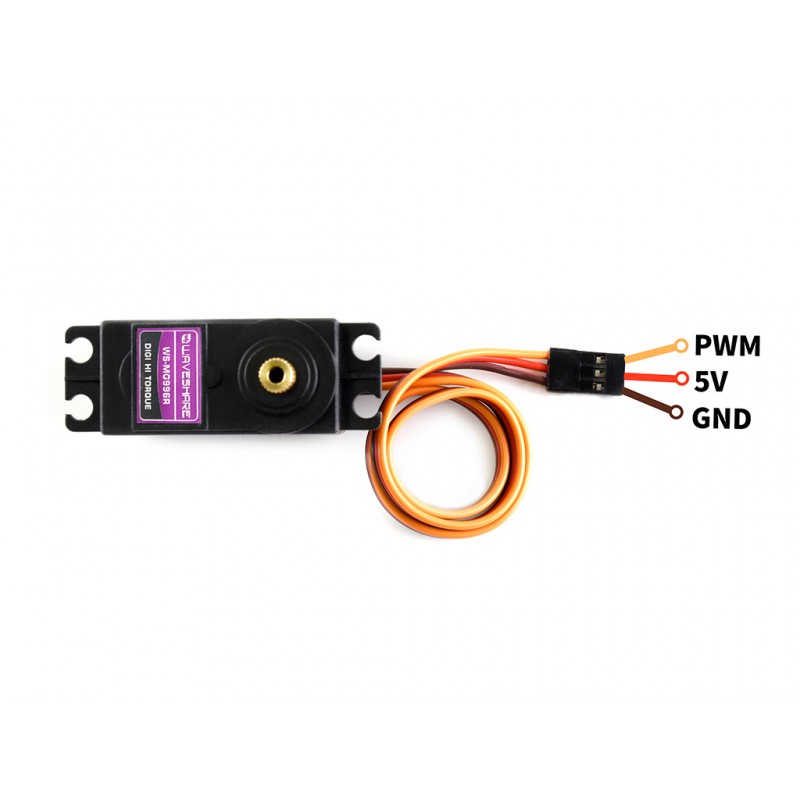
What's in the box?
1 x MG996R Servo with Arm kit

PLEASE NOTE: Raspberry Pi Pico and 14500 batteries are NOT included.
PicoGo Mobile Robot, Based On Raspberry Pi Pico, Self Driving, Remote Control
Smart robot is always the favorite project of electronic enthusiasts, and there've been several robots based on Raspberry Pi. Now, here comes the Pico version: PicoGo!
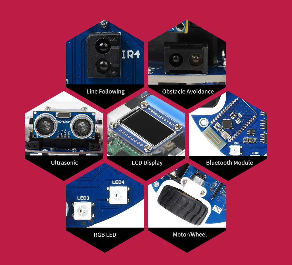
The PicoGo is a smart mobile robot based on Raspberry Pi Pico, it includes ultrasonic module, LCD module, Bluetooth module, line following module, and obstacle avoidance module, all these functions are highly integrated for easily achieving IR obstacle avoidance, auto line following, Bluetooth/IR remote control, and more. With various advanced features, it will help you fast get started with smart robot design and development.
PicoGo smart mobile robot features:
- Standard Raspberry Pi Pico header, supports Raspberry Pi Pico series
- Battery protection circuit: over charge/discharge protection, over current protection, short circuit protection, reverse proof, more stable and safe operating
- Recharge/Discharge circuit, allows programming/debugging concurrently while recharging
- 5-ch infrared sensor, analog output, combined with PID algorithm, stable line tracking
- Onboard multiple smart robot sensors like line tracking, obstacle avoidance, no more messy wiring
- 1.14inch IPS colorful LCD display, 240 x135 pixels, 65K colors
- Integrates Bluetooth module, allows teleoperations like robot movement, RGB LED display color, buzzer, etc. by using mobile phone APP
- N20 micro gearmotors, with metal gears, low noise, high accuracy
- Colorful RGB LED, pretty cool!
*Pico & 14500 Batteries not included*
What's in the box?
- PicoGo base board x1
- PicoGo acrylic panel x1
- 1.14inch LCD Module x1
- Ultrasonic sensor x1
- IR remote controller x1
- USB-A to micro-B cable 1.2m x1
- PH2.0 8Pin cable 5cm opposite side headers x1
- Mini cross wrench sleeve x1
- Screwdriver x1
- Screws and standoffs pack x1
Check out our blog post for this Picogo !
Resources: For any additional information/example code/Guides and Support please see the link below.
https://www.waveshare.com/wiki/PicoGo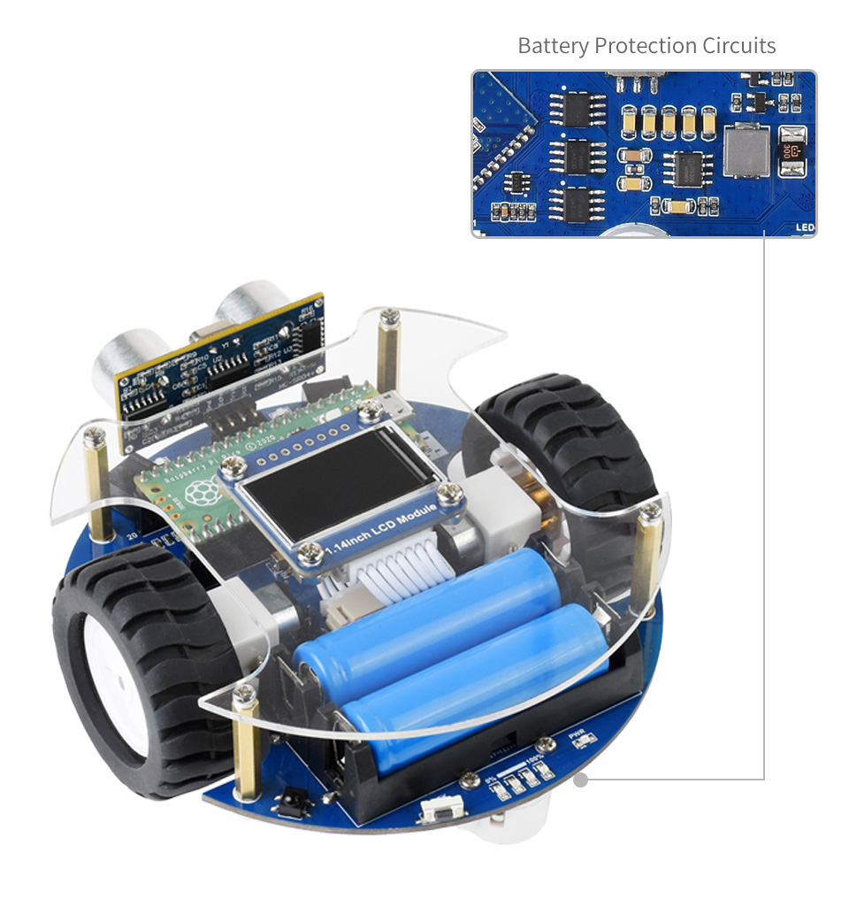
*Pico & 14500 Batteries not included*