
Special Offers


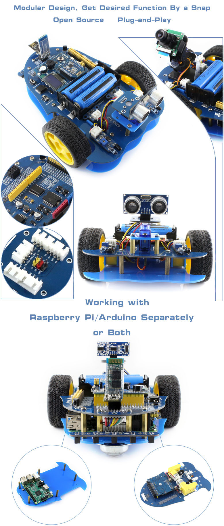
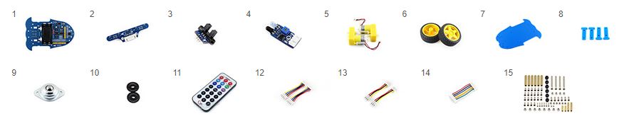
AlphaBot is a robotic development platform compatible with Raspberry Pi and Arduino. It consists of the AlphaBot mainboard, the mobile chassis, and everything required to get it moving.
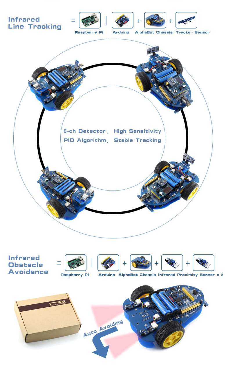
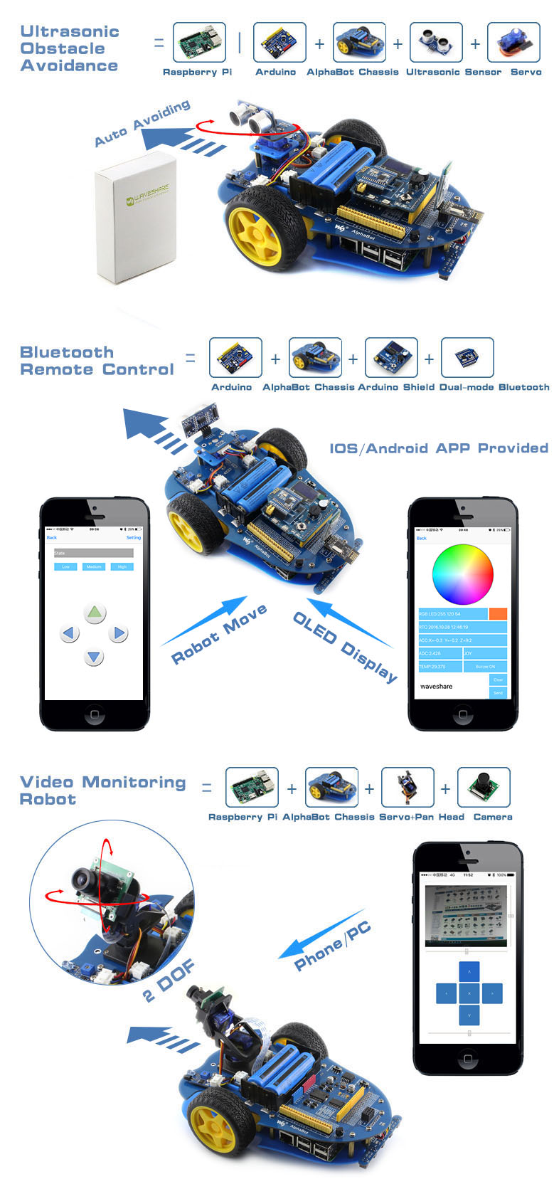
Just connecting a controller board, Raspberry Pi or Arduino, and combined with our open source example code, now it's all ready to start your robotic exploration: line tracking, obstacle avoidance, video monitoring, WiFi/Bluetooth/ZigBee/Infrared remote control, etc.
- Raspberry Pi/Arduino interfaces, works with either one separately, or both
- Arduino extend header, supports Arduino shields
- Modular design, plug-and-play modules like line tracking, obstacle avoidance, speed measuring, etc. eliminating the trouble of connecting mess wires.
- LM298P motor driver with diode protection circuit, more safety
- LM2596 voltage regular, provides stable 5V power to the Raspberry Pi/Arduino
- TLC1543 AD acquisition chip, allows the Pi to use analog sensors
What's on the AlphaBot Mainboard
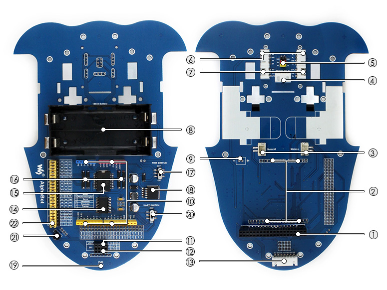
- Raspberry Pi interface: for connecting Raspberry Pi
- Arduino interface: for connecting Arduino
- Motor interface
- Ultrasonic module interface
- Servo module interface
- Obstacle avoidance module interface
- Speed measuring interface
- Battery holder: supports 18650 batteries
- Reserved power input (not soldered): for connecting other external power supply
- Arduino expansion header: for connecting Arduino shields
- UART interface: for connecting Bluetooth module, to control the robot remotely via Bluetooth
- SPI interface: for connecting NRF24L01 wireless module
- Line tracking module interface
- TLC1543: 10-bit AD acquisition chip, allows the Pi to use analog sensors
- LM298P: dual H bridge motor driver chip, up to 2A current
- Anti-reverse diode
- Power switch
- LM2596: 5V regulator
- Power indicator
- UART switch: turn on to enable serial communication between Raspberry Pi and Arduino
- IR receiver: control the robot remotely via infrared
- Raspberry Pi/Arduino selection: select the Raspberry Pi or Arduino to control the robot peripherals
What's in the box?
Please note that the battery length SHOULD be less than 67mm, some batteries with protection plate in the market are NOT supported
- AlphaBot mainboard x1
- Tracker Sensor x1
- Photo Interrupter Sensor x2
- Infrared Proximity Sensor x2
- Motor with gearbox 2PCS x1
- AlphaBot wheel 2PCS x1
- AlphaBot acrylic chassis x1
- Motor mounting plate 4PCS x1
- omni-direction wheel x1
- 20-slots encoder disk 2PCS x1
- IR remote controller x1
- XH2.54 4cm 4Pin 2PCS x1
- XH2.54 4cm 3Pin 2PCS x1
- XH2.54 4cm 7Pin x1
- AlphaBot screws x1
Resources

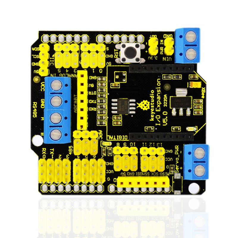
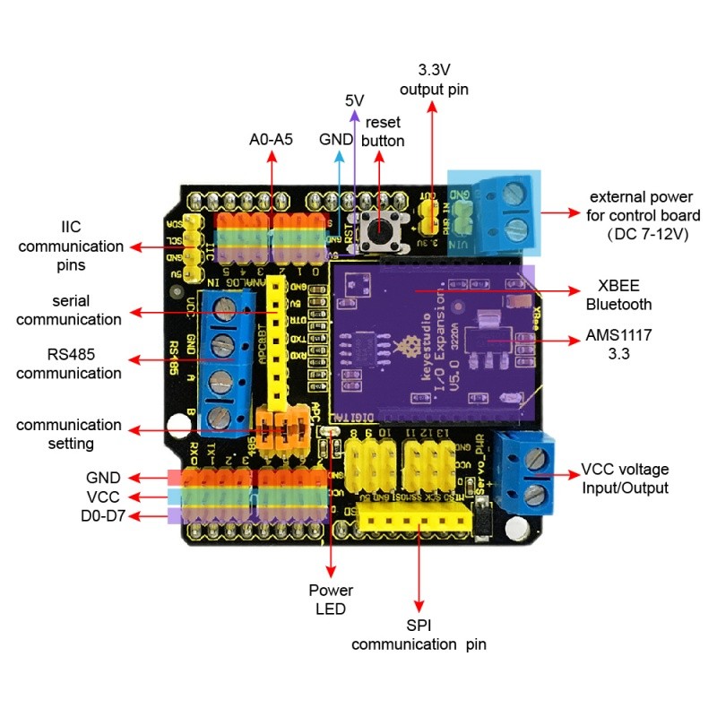
You can change the communication way via the jumper cap on the shield. If all the three jumpers are connected to APC, the shield will realize the XBEE Bluetooth communication. If all jumpers are connected to 485, realize the RS485 communication function.
Onboard also comes with a reset button, a D13 indicator, and some common communication pins of 2.54mm pin pitch, such as serial port, IIC, and SPI communication pins.
Besides, it also has two 2pin terminal blocks. One is VIN GND terminal block, used to supply the external power for the UNO R3 control board, with an input voltage of DC 7-12V. The other is the Servo_PWR terminal block, used for VCC voltage input/output. If not connecting the external voltage, supply 5V for the shield; if connecting the external voltage, VCC voltage is actually the external input voltage.
- Compatible with Arduino UNO R3.
- Comes with 14 digital input/output pins.
- Comes with 6 analog IO pins
- Onboard comes with a digital port power terminal block
- Comes with an external power input terminal block and a input contact pin ( power on the control board with DC 7-12V)
- Comes with an RS485 interface.
- Comes with a reset button
- Comes with a D13 indicator
- Comes with a XBEE Bluetooth interface
- Can connect three jumper caps (APC and 485) to switch the XBEE Bluetooth communication or RS485 communication.
- Comes with I2C, serial port and SPI communication pins
- Onboard comes with a DC 3.3V output pin
- Dimensions: 58.5mm x 57.5mm x 20mm
- Weight: 26.2g
Pinout diagram
1 x XBEE Shield with RS485 for Arduino UNO
Resources
Product wiki page

Note: the CM4 is NOT included. Please buy it separately if necessary.
The Nano Base Board (B) For Raspberry Pi Compute Module 4, is the Same Size As The CM4 and is suitable For Evaluating The Raspberry Pi CM4 Or Being Integrated Into End Products.
This module is Compact, Yet Complete, featuring: Standard CM4 Socket, 40PIN GPIO, Gigabit Ethernet, USB2.0, DSI, CSI, 3.5mm Audio Jack...
Specifications
CM4 SOCKET - suitable for all variants of Compute Module 4
NETWORKING - Gigabit Ethernet RJ45 connector
CONNECTOR - Raspberry Pi 40PIN GPIO header × 1
USB - USB 2.0 Type A connector × 1
DISPLAY - MIPI DSI port × 1 (15pin 1.0mm FPC connector)
CAMERA - MIPI CSI-2 port × 1 (15pin 1.0mm FPC connector)
VIDEO - Mini HDMI port × 1, supports 4K 30fps output
AUDIO - 3.5mm jack
STORAGE - Micro SD card socket for Compute Module 4 Lite (without eMMC) variants
POWER INPUT - 5V
DIMENSIONS - 56 × 41mm
What's On Board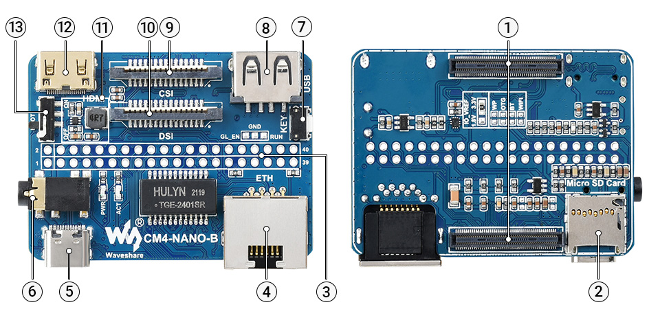
- CM4 socket
suitable for all variants of Compute Module 4 - Micro SD card slot
for connecting a Micro SD card with pre-burnt image (Lite variant ONLY) - 40PIN GPIO header
for connecting sorts of HATs - Gigabit Ethernet RJ45 connector
- Power supply / Programming
5V power supply, or used for eMMC burning - 3.5mm audio jack
- User button
- USB2.0 connector
for connecting sorts of USB devices
- CSI connector
MIPI CSI camera interface - DSI connector
MIPI DSI display interface - MP1658
- Mini HDMI connector
supports 4K 30fps output - BOOT switch
ON: Switch USB to Type C interface, will enter download mode when powered on (configured as a large-capacity disk through RPI boot)
OFF: Switch USB to Type A interface, will not enter download mode when powered on (booted from eMMC or Micro SD card)
Outline Dimensions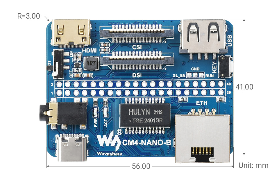
What's in the box?
1 x CM4-NANO-B

1 x 2*20PIN color-coded straight pin header

Resources
WIKI: CM4-NANO-B

This lovely little lens set is the best way to easily expand the field of view of your Raspberry Pi camera!
This lens kit means that you can use your camera module in many exciting ways:
- 1x Wide-angle lens: Ideal for capturing those landscape shots/night sky time-lapses
- 1x Macro lens: Beautiful close-up images of anything from insects to circuit boards
- 1x Fish-eye lens: Security systems and crazy 180° FOV shots
Perfect for taking shots from anywhere from your desk to the edge of space this lens comes with a back splint which means you can also use it with other camera devices such as your mobile phone.
Each lens screws into the clip which fits perfectly onto your camera module.
Features
- Compatible with the known universe *
- High-class glass lens, high clarity.
- No *vignetting or dark circle.
- Lens covers to protect the camera lenses
- Material: ABS & aluminum alloy
- Compatible with most of the official Raspberry Pi Camera Modules
* Vignetting is a phenomenon in which the corners of an image appear darker than the center due to the blocking or shading of light rays by external objects or the physical dimensions of a lens
What's in the box?
1 x camera clip
3 x screw on lenses
Please note: The third lens isn't missing; it’s actually screwed into the second lens.

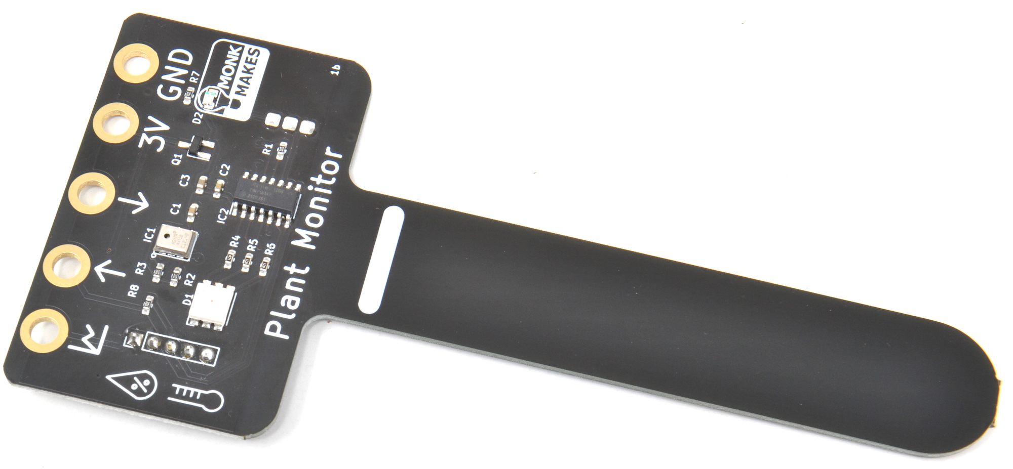
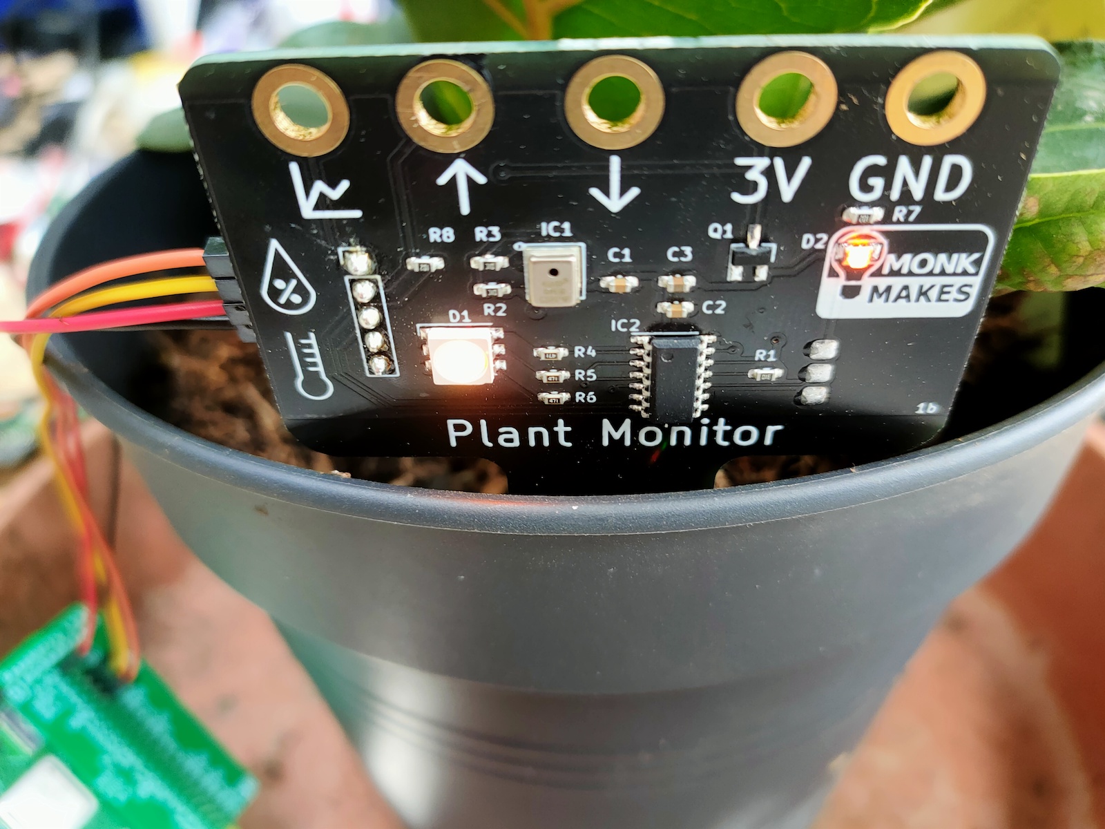
Monitor soil moisture, temperature and relative humidity measurement with the Plant Monitor. This board is compatible with the BBC micro:bit, Raspberry Pi and most microcontroller boards.
Specifications
- Alligator / croc clip rings
- Ready soldered header pins for your choice of microcontroller.
- Easy to use UART serial interface
- Additional analog output for moisture only
- Built-in RGB LED
What's in the box?
1 x Moisture Sensor
Resources
Instructions (All platforms)
Instructions (Micro:bit)
Instructions (Raspberry Pi)
Instructions (Pico)
Instructions (Arduino)
Datasheet
Hi Res Images (Google File Share)

The Spy Camera for Raspberry Pi is smaller than a thumbnail with a high enough resolution to see people, or ghosts, or whatever it is you're looking for. It's about the size of a cell phone camera - the module being just 8.5mm x 11.3mm - and has a stick-on back so it's easy to mount in a doorbell or behind a teddy bear's eye (might as well be creative!)
The camera comes with a 289mm (11.4") long cable so you can extend and mount your Pi away from the camera. Like the Raspberry Pi Camera Board, it attaches to your Raspberry Pi by way of one of the two small sockets on the board upper surface. This interface uses the dedicated CSI interface, which was designed especially for interfacing to cameras. The CSI bus is capable of extremely high data rates, and it exclusively carries pixel data.
The camera is connected to the BCM2835 processor on the Pi via the CSI bus, a higher bandwidth link which carries pixel data from the camera back to the processor. This bus travels along the ribbon cable that attaches the camera board to the Pi.
The sensor itself has a native resolution of 5 megapixel, and has a fixed focus lens onboard. In terms of still images, the camera is capable of 2592 x 1944 pixel static images, and also supports 1080p30, 720p60 and 640x480p60/90 video.
CSI camera port works with Raspberry Pi 3/4 B
Specifications
- Sensor: OV5647, 5MP 2592x1944 pixels
- Pin: 22
- Peach: 0.5mm
- AVDD: 2.7-3.3V (Typical2.8V)
- DVDD: 1.45-1.8V
- DOVDD: 1.7-3.3V
- Lens Structure: 4P (650nm)
- EFL: 3.52
- FNO: 2.8
- FOV: 70 degree
- Output Format: YUV or RAW RGB
- 1080p video at 30 FPS (or 60 FPS at 720p, 90 FPS at 480p)
- F2.9 lens, 3.4 mm focal length
- 53.50 degrees horizontal, 41.41 degrees vertical field of view
- Approx. dimensions of circuit and camera: 60 x 11.5 x 4.5mm
The new Raspberry Pi OS release includes the new Picamera2 Python camera interface.
What's in the box?
1 x camera module
Support
Please download the camera user guide here.

The module uses a full-size 15-pin connection which is compatible with Raspberry Pi Model B boards (Pi 4, 3B+, 3, 2, B+). The short size makes it handy for compact Raspberry Pi photography projects, custom 3D printed cases or just simply playing with the various camera commands with your bare board - without the need for a camera case.
Specifications
- Compatible with Model B Raspberry Pi boards (Pi 4, 3B+, 3, 2, B+)
- OV5647 Sensor
- Compatible with libcamera and raspicam commands
- Compact size - just 35mm long!
- Includes foam gaskets for creative mounting
- Images up to 2592x1944
- Video up to 1920x1080
- Sensor: OV5647
- Pixels: 5MP
- Focal length: ~3.9mm
- CMOS size: 1/4"
- Field of View: ~73°
- Aperture: F2.4
- Depth of Field: ~20cm
- Distortion: < 1.5%
- Still Image: up to 2592x1944
Video
- 1920 x 1080p @30
- 1280 x 720p @60
- 640 x 480p @60
- 640 x 480p @90
The new Raspberry Pi OS release includes the new Picamera2 Python camera interface.
What's in the box?
1x Mini Camera Module
Resources
- How to Install & Use the Raspberry Pi Camera Module (different camera but the process and commands are the same)
- Libcamera and the legacy Raspicam stack
- Libcamera introduction and usage
- Raspicam (legacy) introduction and usage
- OctoPrint for 3D print monitoring
- MotionEyeOS Raspberry Pi CCTV

Misusing or mishandling a lithium-ion battery may cause a FIRE or EXPLOSION which can result in INJURY or DEATH.
Description:
The LiitoKala Lii-402 Smart Charger for Lithium Ion and NiMH batteries is the perfect bench mate to keep your radios, robotics and flashlights running at peak efficiency. In a sea of endless chargers for sale, we have found one that will meet and exceed the needs of many consumers.
Specifications:
Product name: Liitokala Lii-402 Micro USB 4Slots Battery Charger
Input : Micro USB DC 5V/2A
Output: 1.42V
4.2V±0.05V
3.65±0.05V
4.35±0.05V
Current: 2000mA*1 1000mA*2 700mA*3 500mA*4
Constant voltage, cut-off current: less than 100mAh
Standby current: less than 15mAh
Compatible with:
Ni-MH/Cd
AA/AAA/A/SC Sizes
3.7V Li-ion battery including
26650,22650,26500,18650,18490,17670,17500,16340,14500,10440
Size: 112mm x 90mm x 30mm (L x W x H)
Weight: 150 grams (incl. micro cable)
USB Output function
1. 0pen-circuit voltage of USB output : 4.9-5.3V; and the 4th slot is fixed for the USB discharge power source
2. Output current: 1000mAh
3. Open circuit current: <1mAh
4. The corresponding voltage is 4.75-5.25V under 1000mAh current
5. Cut-off voltage for discharge protection: 3.0±0.1V
1 x Liitokala Lii-402 Micro USB 4Slots Battery Charger
1 x USB Cable
1 x Power supply

Aid young children and elementary school students to increase their physical knowledge in a hands-on form with a simple series circuits
Specifications:
- Colour: Black
- Material: Plastic
- Battery: 2 x AA Battery (Not included)
What's in the box?
1 x Bulb Holder
1 x Battery Holder
1 x Bulb
1 x Conductive Line
2 x Crocodile clips
(batteries not included)

Specifications
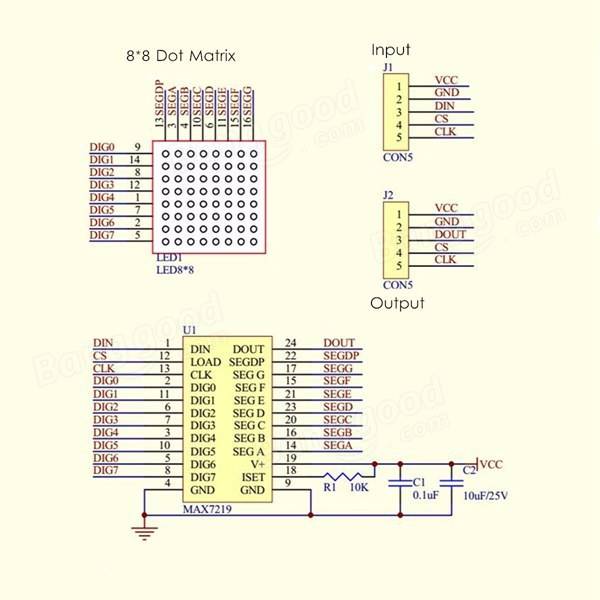
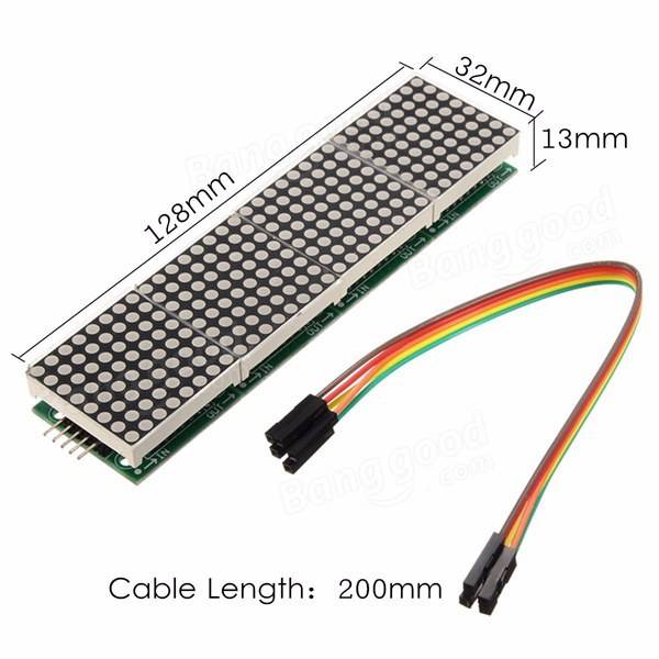
A single module can drive a 8x8 dot matrix common cathode
Working voltage: 5V
Module size: 12.8 x 3.2 x 1.3 cm (L*W*H)
With 64 fixing screw holes, hole diameter: 3mm
Module with input and output interfaces, support for cascading multiple modules
What's in the box?
1 x MAX7219 Dot Matrix Module
1 x 5pin jumper Cable
Resources
Wiring
1. The left side of the module is the input port, and the right is the output port.
2. Control of a single module, the input port only need to receive CPU.
3. The more a module cascade and input end of the first module is connected with the CPU and input end of the input end of the output end is connected to the second module, output terminal of the second module connected with the three modules, and so on.
For example: 51 SCM
VCC→5V
GND→GND
DIN→P2.2
CS →P2.1
CLK→P2.0
https://max7219.readthedocs.io/en/0.2.3/
Clock example
Python Library

The Kitronik Inventor's Kit for Arduino is a great way to get started with programming and hardware interaction with the Arduino in the classroom. This Inventor's Kit contains everything you need to complete 10 experiments including using LEDs, motors, light sensors and capacitors.
Arduino is an open-source code-able electronics platform, which has been designed for anyone making interactive projects. Arduino board can process inputs from many sensors, and also control outputs such as LEDs and motors.
The Arduino is controlled by the code with which it is programmed. This code is written in the Arduino programming language, using the Arduino development environment. Once complete the code is easily transferred to the Arduino board using a simple USB lead.
To get you off to a flying start, we have included an easy to follow tutorial book which guides you through creating the 10 experiments. You don't need any experience with programming as the tutorial book will guide you every step of the way. You'll be programming and creating circuits in no time!
Note:
- This kit requires assembly.
- No soldering is required and you can build your first circuit in minutes!
- This kit does not include an Arduino UNO.
- This kit is available as a single pack or as a pack of 20.
Features:
- No soldering required - build your first circuit in minutes!
- Make 10 experiments included in the provided step-by-step tutorial book.
- All parts are included to conduct the 10 experiments.
- Small Prototype Breadboard included for fast prototyping.
What's in the box?
1 x Mounting Plate.1 x 7 Segment Display.
1 x Servo.
1 x Potentiometer - Vertical Type (finger adjust) 100K.
1 x Finger Adjust Spindle.
4 x Plastic Spacer 10mm.
1 x Small Prototype Breadboard.
1 x Terminal Connector.
4 x Push Switch.
1 x Motor.
1 x Transistor.
2 x Red 5mm LED.
2 x Orange 5mm LED.
2 x Yellow 5mm LED.
2 x Green 5mm LED.
1 x RGB 5mm LED.
1 x Fan Blade.
5 x 2.2KΩ Resistor.
5 x 10KΩ Resistor.
10 x 220Ω Resistor.
20 x Male to Male Jumper Wires.
1 x 470uF Electrolytic Capacitor.
1 x Piezo Element Buzzer.
4 x Pan Head M3 Machine Screw.
1 x Phototransistor.
Video: https://youtu.be/aswor6BKXSY
Requires:
- An Arduino board such as The Arduino Uno, Compatible Uno, Maker Uno or Maker Uno Plus
- Phillips Screwdriver.
- Terminal Block Screwdriver.
- USB A to USB B Cable for Uno or the micro USB cable for Maker Uno and Maker Uno Plus
Inventors Kit Additional Online Resources:
- Tech Talks - live stream playback.

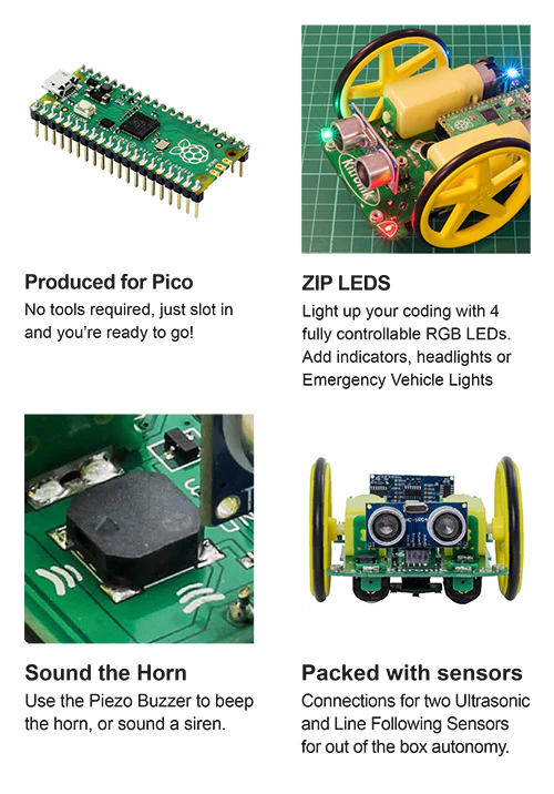
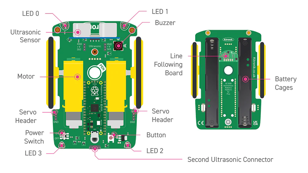
The Kitronik Autonomous Robotics Platform Pico, a fun and hands-on introduction to Robotics with the Raspberry Pi Pico.
The Kitronik Autonomous Robotics Platform for Raspberry Pi Pico is a fun and hands-on introduction to buggy robotics. The easy to follow booklet provided with the kit guides you through all of the steps required for you to take control of your robot. The Robotics Platform has been designed to grow with you and provided additional servo and ultrasonic sensor connectors for more advanced projects. This buggy requires a Raspberry Pi Pico with pin headers attached, you can obtain a Raspberry Pi Pico with headers attached here.
The kit is supplied with the autonomous robotics platform chassis, 2 wheels and tyres, a Kitronik line-following sensor board, and an ultrasonic sensor. The kit requires no soldering and only minimal mechanical assembly. Fit the tyres to the wheels, push the wheels onto the pre-mounted motors and both the line following sensor and ultrasonic distance sensor plug straight into the board. Once put together, push the Raspberry Pi Pico into the onboard connector, add 4 x Alkaline AA batteries to the battery holders underneath and you are done. Your robot buggy is ready for instruction.
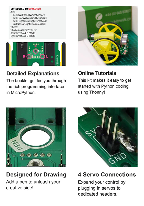
The included booklet guides you through every step of getting to know your robot. It contains a detailed assembly guide, info on preparing the Raspberry Pi Pico, instructions for installing an editor (Thonny), and instructions on how to write code for every feature of the Robotics Platform. No corner of the board is left unexplained.
As well as the easy to follow getting started guide, we have also produced online tutorials which go into more detail on coding the key features of the board. The links to the tutorials can be found in the resources section at the foot of this page.
To help make programming the robot as simple as possible, Kitronik has developed a set of Micropython modules, which can be found here. More information on this can be found in the booklet supplied with the kit. If you aren't familiar with GIT, we've created an online beginners guide to help you get up to speed. You can find the guide here (https://kitronik.co.uk/GitGuide).
Features:
- A fun and hands-on introduction to buggy robotics.
- The Robotics Platform has been designed to grow with you, start small then add complexity later.
- The kit ships with a detailed guide booklet backed up with freely available online tutorials.
- The autonomous robotics platform introduces the user to light, movement, and sensing so the robot can be as hands-on or hands-off as want it to be.
- Program your buggy to react to the world around it.
- Learn to code with MicroPython, using our simple to follow guides and the beginner-friendly Thonny editor.
- Just add the Raspberry Pi Pico, some alkaline batteries, and some code and watch your buggy come to life!
- This buggy is not supplied with a Pico, you can obtain a Raspberry Pi Pico here.
What's in the box?
- 1 x Autonomous robotics buggy chassis PCB.
- 2 x Kitronik 5 spoke wheels and tyres.
- 1 x Kitronik line following sensor board.
- 1 x Ultrasonic Sensor.
Dimensions:
- PCB Length: 126mm.
- PCB Width: 80mm.
- Wheel Diameter (with tire): 67.5mm.
Video: https://youtu.be/vPd4gt_Gt4U
Requires:
Resources:
- Kitronik Online Tutorials, using the Pico-ARP;
- Motors.
- Lights, switch, and buzzer.
- Line Following Sensors.
- Ultrasonic Distance Sensor.
- Using the servo connectors.
- First steps with the Raspberry Pi Pico, MicroPython, and Thonny.
- Kitronik Beginners guide to GitHub.
- A practical guide to Modules, Micro Python and the Raspberry Pi Pico.
- Kitronik Micropython modules for ARP-Pico.
- Pico Datasheet.

- Getting started with MicroPython on the Pico.
- Thonny, the beginner-friendly editor.

Features:
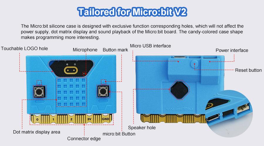
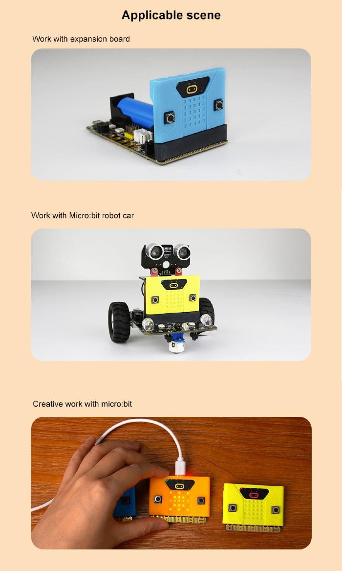
- Designed for micro:bit V2:
- micro:bit V2 (single board)
- micro:bit V2 kit and V2 Kit including batteries
- micro:bit V2 Club (10 x Go bundle)
- Available in three good-looking colors: (choose your preferred color)
- Orange
- Yellow
- Blue
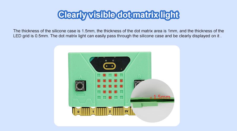
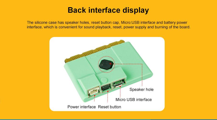
- The precise hole allows users to use all functions of the micro:bit board.
- Environmentally friendly materials, excellent workmanship.
- Material: Silicone
- Dimension: 56.5 x 10.2 x 37mm
What's in the box?
1 x Silicon Case for micro:bit V2 (Chosen Color)
100% cotton Unisex T-shirt from the Cytron for every maker that loves making stuff. Simple yet comfortable!
Comes in black color with the slogan of TRUST ME I'M A MAKER
There are several sizes of this T-shirt to accommodate everyone :) Please choose the preferred size next to the main photo. It is Unisex T-shirt so it is suitable for both male and female maker :)
- XS (Extra Small) Size
- S (Small) Size
- L (Large) Size
- M (Medium) Size
- XL (Extra Large) Size
- XXL (Double Extra Large) Size
- XXXL (Triple Extra Large) Size
Features:
- Coming from makers to makers :)
- 100% cotton, super comfortable
- The black color with:
- Front: Slogan: TRUST ME I'M A MAKER
- Back: Cytron Logo
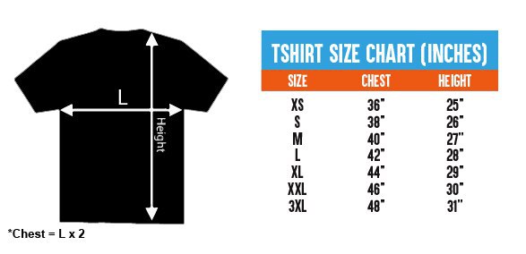
- Available Sizes:
- Extra Small (XS):
- 36" or 91.44cm for the Chest (Chest = 2 x L)
- 25" or 63.5cm for Height
- Small (S):
- 38" or 96.52cm for the Chest (Chest = 2 x L)
- 26" or 66.04cm for Height
- Medium (M):
- 40" or 101.6cm for the Chest (Chest = 2 x L)
- 27" or 68.58cm for Height
- Large (L):
- 42" or 106.68cm for the Chest (Chest = 2 x L)
- 28" or 71.12cm for Height
- Extra Large (XL):
- 44" or 111.76cm for the Chest (Chest = 2 x L)
- 29" or 73.66cm for Height
- Double Extra Large (XXL):
- 46" or 116.84 cm for the Chest (Chest = 2 x L)
- 30" or 76.2 cm for Height
- Triple Extra Large (XXXL):
- 48" or 121.92 cm for the Chest (Chest = 2 x L)
- 31" or 78.74 cm for Height
- Extra Small (XS):
What's in the box?
1 x Trust Me T-Shirt - Black (Chosen Size)
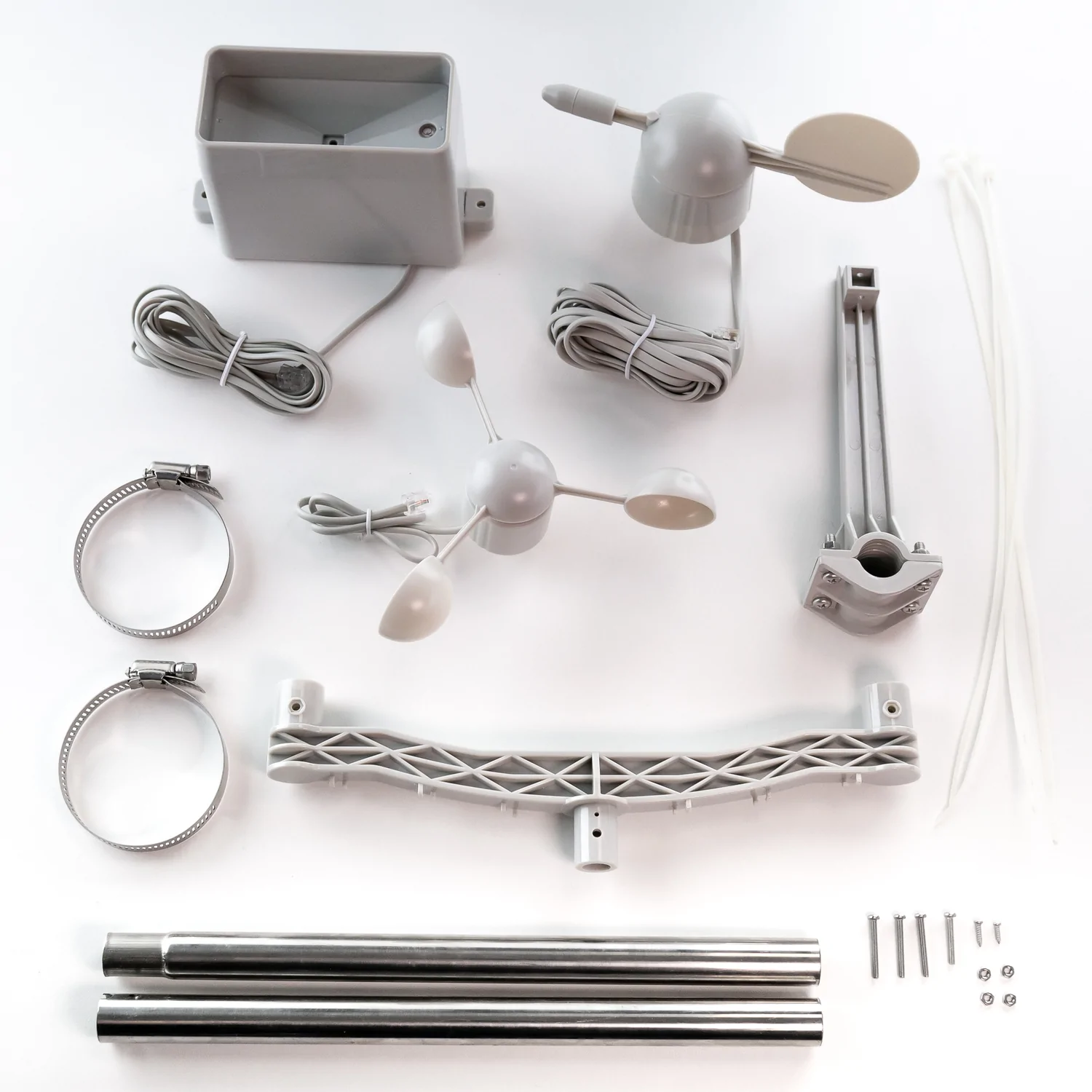
Want to build your own weather station? This sensor kit has a cup anemometer and wind vane to measure wind speed and direction and a tipping bucket style rain gauge, together with associated mounting hardware.
The sensors in this kit are active mechanical sensors that work by physically interacting with the wind and rain. They use magnets, reed switches and moving parts to produce simple signals that a microcontroller or single board computer can use to calculate wind speed, wind direction and rainfall.
The sensor cables are terminated in RJ11 connectors (each sensor only uses two wires though, so if you wanted you could snip off the ends and connect the wires to a different kind of connector). Armatures to mount the sensors are included, as well as a short metal mast that can be lashed to the top of a suitable pole with the included jubilee connectors.
Please note that this kit contains the mechanical wind and rain sensors only, and doesn't include any electronic components. You'll likely want to hook these sensors up to something like a Weather HAT (for Raspberry Pi), a weather:bit (for micro:bit) or a Weather Shield (for Arduino).
Features
- Three mechanical sensors: rain gauge, anemometer, and wind vane
- Passive electronics with sealed magnetic reed switches—no complex libraries required
- Rain gauge measures 0.011" (0.2794 mm) increments per bucket tip
- Anemometer detects wind speed with one switch closure per rotation (1.492 MPH = 1 closure/second)
- Wind vane reports direction as variable voltage; reliably resolves 8 cardinal directions
- Compatible with Arduino, ESP32, and other microcontrollers
- RJ11-terminated cables for clean, modular connections
- Minimal assembly required with standardized connectors
- Direct access to raw sensor data without proprietary protocols
What's in the box?
1 x Wind Vane
1 x Anemometer
1 x Tipping Bucket Rain Gauge
1 x Two-Part Mounting Mast
1 x Rain Gauge Mounting Arm
1 x Wind Meter Mounting Bar
2 x Mounting Clamps
4 x Zip Ties
Resources
Getting Started with Weather HAT
This comprehensive guide from RPi contains loads of detail on how to DIY your own weather station (it also contains lots of info about how these sensors work and how you can write code for them).
If you need pictures of how everything goes together, check out SparkFun's excellent hookup guide!

A meteorologically minded Raspberry Pi HAT designed to make hooking up weather sensors a breeze (or a squall, or a gale).
Weather HAT is a tidy all-in-one solution for hooking up climate and environmental sensors to a Raspberry Pi. It has a bright 1.54" LCD screen and four buttons for inputs. The onboard sensors can measure temperature, humidity, pressure and light. The sturdy RJ11 connectors (remember those?) will let you easily attach wind and rain sensors. It will work with any Raspberry Pi with a 40 pin header (that's most of them except the really old ones).
You could install it outside in a suitable weatherproof enclosure (like a waterproof junction box or even a Tupperware container) and connect to it wirelessly - logging the data locally or piping it into Weather Underground, a MQTT broker or a cloud service like Adafruit IO. Alternatively, you could house your weather Pi inside and run wires to your weather sensors outside - making use of the nice screen to display readouts.
Please note: the wind and rain sensors are sold separately.
Features
- 1.54" IPS LCD screen (240 x 240)
- Four user-controllable switches
- BME280 temperature, pressure, humidity sensor (datasheet)
- LTR-559 light and proximity sensor (datasheet)
- Nuvoton MS51 microcontroller with inbuilt 12-bit ADC (datasheet)
- RJ11 connectors for connecting wind and rain sensors (sold separately)
- HAT-format board
- Fully-assembled
- Compatible with all 40-pin header Raspberry Pi models
- Python library
- Schematic
What's in the box?
1 x Weather HAT
2 x 10mm standoffs
Raspberry Pi and accessories are sold separately
Software
We've put together a Python library to give you easy access to all Weather HAT's functions, together with straightforward examples to help you learn how to read the sensors and use all the individual parts. There's also a weather station example that shows you how it's possible to combine all the functions into an application.
Our Getting Started tutorial contains a thorough walkthrough of Weather HAT's functionality plus beginner friendly instructions for installing the Python library and running the examples.
Notes
- Want to add on more I2C sensors? No problem, there's an solderless I2C header located on the back of the HAT that you can poke jumper / DuPont wires in to.
- If you'd like to hook up more analog sensors (3.3v max) we've broken out some extra ADC channels on the front of the board, as well as a convenient 3v3 power and ground.
- We've found two standoffs at the GPIO edge to be sufficient to keep this HAT firmly in place, but if you're attaching it to a full-size Pi and want to add standoffs at every corner you can pick up some more.
- Dimensions: 65 x 56.5 x 19 mm (L x W x H, including header and connectors)

Do you want to build an auto plant watering system but don’t know where to start?
Or you are a teacher and wanted to help your students to build the auto plant watering system in the most effective way?
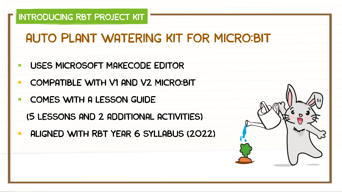
This project kit comes with the new Maker Soil Moisture Sensor.
A capacitive moisture sensor which measures the soil moisture level by changing the probe capacitance and does not erode the sensor probe easily.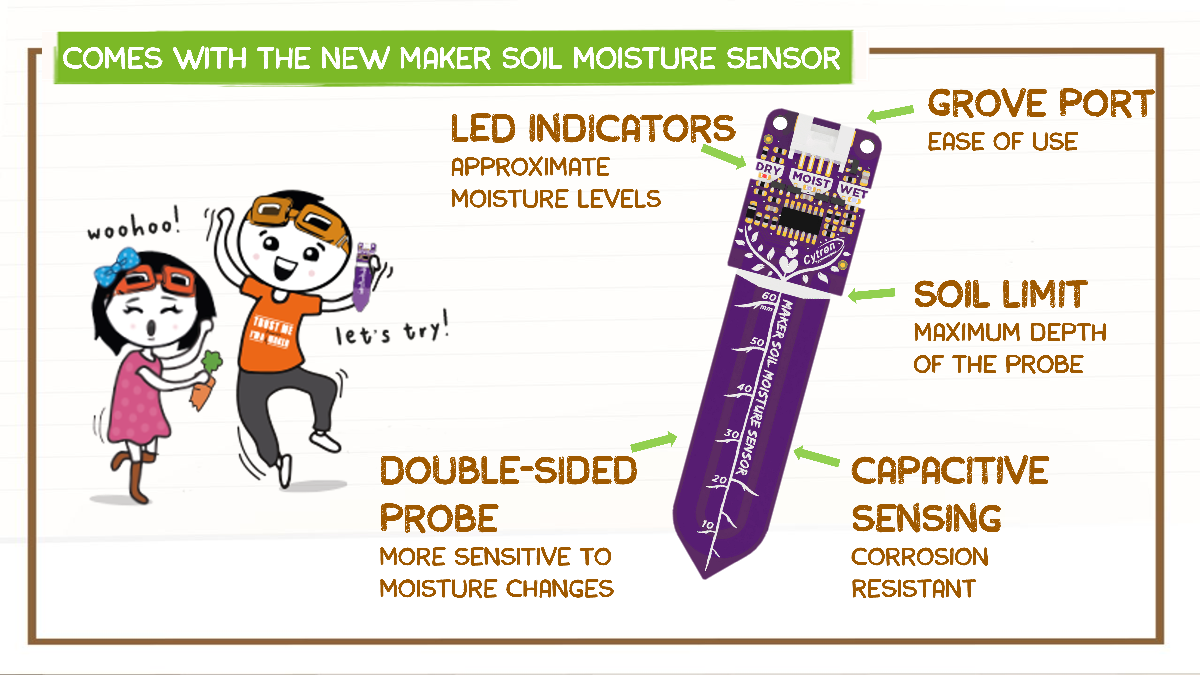
The Lesson Guide is written in simple language and comes with a step-by-step guide to make an auto plant watering system.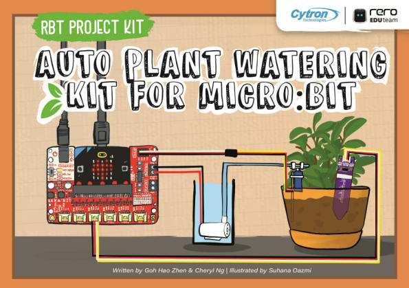
Click here to download PDF English Version
Lesson 1 : Hello!
- Introduction to micro:bit and MakeCode.
Lesson 2 : What’s the Soil Moisture Level?
- Display soil moisture level through micro:bit by using Maker Soil Moisture Sensor.
Lesson 3 : Dry? Moist? Or Wet?
- Monitor the soil moisture level and differentiate it between dry, moist and wet.
Lesson 4 : Water the Plant
- Turn on the water pump to water the plant when the soil is dry.
Lesson 5 : Servo Motor, Direct the Pipe!
- Control the direction of the water pipe by using a servo motor to water the plant thoroughly.
Additional Activities: Visualize Soil Moisture Level, Music On
- Plot a bar graph to show the soil moisture level and make the auto plant watering system to play melodies and sound notifications.
What’s in the box?
1 x Lesson guide (English Version)
1 x Maker Soil Moisture Sensor
1 x REKA:BIT (without micro:bit V2)
1 x Micro Submersible Water Pump DC 3V-5V with Pipe
1 x Analog Micro Servo 9g (3V-6V) with servo horns and screws
1 x Grove 4 Pin Buckled 50cm Cable
1 x Servo Male - Female Extension Cable 30cm
1 x 4xAA battery holder with DC plug
4 x PKCELL Heavy Duty AA Battery
1 x Tiny Phillips Screwdriver - Transparent
2 x Popsicle stick
3 x Cable Ties
2 x Double Sided Tapes

This SD card to SD card extension cable is perfect for protecting your SD card port! The flat flex cable is 45cm long, so it's perfect for mounting your SD card separately for easy access.
SD to SD Extension Cable Features:
- SD Card Male to SD Card Female
- Flex Cable ~ 45cm
- Supports SD Card Sizes: 16GB, 32GB 64GB 128GB
- Supports SD/SDHC/SDXC Cards
What's in the box?:
1 x SD Extension Cable

Finally available following public demand after so many of you spotted this mug on Raspberry Pi Tweets and images, this Black Design Raspberry Pi mug is the ultimate holder of coffee, tea and other late-night project beverages!
With a 330ml capacity for your favourite brew combined with superb styling, this mug is a great companion for Raspberry Pi makers and fans across the planet. Get dipping those biccies!
We also stock the original red design! Don't forget to grab a coaster whilst you're at it
Features:- Black colour with White Raspberry Pi designs
- Dishwasher safe
- 80mm diameter x 90mm tall
- 330ml capacity
- Bright and colorful!
The team at Raspberry Pi Foundation has extensively tested these mugs and can confirm that they are tea-, coffee-, and hot chocolate-compatible. They can also be used for cold drinks if that's your preference.
Note: While tested to over 1,000 domestic dishwasher cycles, it is recommended that you hand-wash this mug to keep it in tip-top condition.
What's in the box?1 x Raspberry Pi Black Ceramic Mug

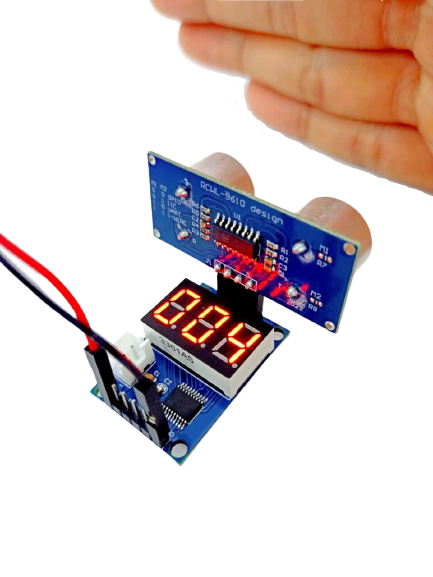
This module adopts an 8-bit MCU as the main control chip, it can be applied in distance measurement, testing the performance of the HC-SR04 ultrasonic module. Plus, you can use this module in two ways since it supports Serial Port Display and Digital Tube Display.
Specifications
- Integrated STM8S103 High-Performance Microprocessor
- Interfaces:
- Digital Tube Display
- Serial Port Data Output
- Input Voltage: 5V
- LiPo Connector: 2.54mm socket (5V power supply)
- Measuring Distance: 3cm - 400cm
- Plate Size: 25mm x 35mm
- Weight: 7g
How To Use
Measured distance can be displayed via the digital tube or serial port:
- Digital Display: directly connect ultrasonic sensor and provide 5V power supply (using wire jumpers or LiPo battery).
- Serial Port Output: connect the display module pins (VCC, TX, RX, GND) to USB to TTL converter pins (5V, RX, TX, GND) respectively. Select 9600 baud transmission rate and the output format is "D: XXX", where XXX represents the distance in centimeters.
Note: No code is required to use this module! Plug and play, very easy to use for beginners.
Additional Notes
When measuring the distance, the area of the measured object should not be less than 0.5 square meters, and it should be smooth and have strong reflectivity. Failure to do so will affect the test result.
Valid measuring distance: 3-400cm. If it is longer than this range, it will result in incorrect data or shows a 000 screen.