
Special Offers


Commonly used in machine parts, die fixture, and clamping, Allen head screws enable you to drive in and secure this type of fastener where there is not sufficient space to use a traditional socket or wrench.
Great for building your own CNC project or 3D printer
Specifications
- Black
- M5 x 16mm
- Steel Alloy
- pack of 10
What's in the box?
10 x Screws

- Great for electronic projects and kits.
- Perfect use for home, office and industry electrical equipment and electrical appliances
- Size: 10mm
- Voltage: 1.8V ~ 2.2V for Red & Yellow, 3.0V ~ 3.4V for Blue, Green & White
- Current: 20 mA
- Luminous Intensity: 5000 MCD
- Colour: RED, BLUE, YELLOW, GREEN, WHITE
- Lens Color : Diffused
| 10Pcs Five Colors 10mm Round Bright Light LED Assortment Kit | ||||
| Color | Size | Current(mA) | Lens Color | Quantity |
| Red | 10mm | 20 | red | 2Pcs |
| White | 10mm | 20 | white | 2Pcs |
| Yellow | 10mm | 20 | yellow | 2Pcs |
| Green | 10mm | 20 | green | 2Pcs |
| Blue | 10mm | 20 | blue | 2Pcs |
Resources
Python library
Introduction

Description:
ATmega328 is commonly used in many projects and autonomous systems where a simple, low-powered, low-cost micro-controller is needed.
The Arduino Compatible Nano V3 development board is a microcontroller board based on the Arduino Nano
Specifications:
- Microcontroller Atmel ATmega328
- Operating Voltage (logic level): 5V
- Input Voltage (recommended): 7V ~ 12V
- Input Voltage (limits): 6V ~ 20 V
- Digital I/O Pins: 14 (of which 6 provide PWM output)
- Analog Input Pins: 8
- DC Current per I/O Pin: 40mA
- Flash Memory: 32KB (ATmega328) (of which 2 KB used by bootloader)
- SRAM: 2KB (ATmega328)
- EEPROM: 1KB (ATmega328)
- Clock Speed: 16MHz
1 x Arduino Compatible Improved Version Nano V3.0 with headers pre-soldered
1 x USB cable
Resources:
Getting started with Arduino products
This pre-built Edge Connector Breakout Board for the micro:bit gives access to all the important pins on the bottom edge of the micro:bit.
Looking to do more with your micro:bit? Unlock its potential with this pre-built version of our Edge Connector Breakout Board! This breakout board has been designed to offer an easy way to connect additional circuits and hardware to the pins on the edge of the micro:bit. It provides access to all of the micro:bit processor pins allowing a lot of extra functionality to be added. The datasheet (below) includes a helpful diagram explaining the function of every pin on the micro:bit.
This Edge Connector Breakout Board for the micro:bit gives access to all of the important pins on the bottom edge of the micro:bit. 21 pins are broken out in total; providing additional I/O lines, direct access to buttons A and B, the LED matrix outputs and the I2C bus. Please refer to the datasheet below for more details.
The micro:bit pins are broken out to a row of pin headers. These provide an easy way of connecting circuits using jumper wires. The SCL and SDA pins are separated at the edge of the board (solder pads) providing easy identification. The PCB includes a prototyping area with 3V, 0V and unconnected rows that can be soldered to. This allows the easy connection of switches, sensors and any pull-up or pull-down resistors etc. as required.
To use the breakout board the micro:bit should be inserted firmly into the connector as shown below: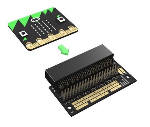
Note:
- This product is supplied with straight double row PCB pin headers already soldered to the breakout board
Features:
- Features a dedicated pin strip for quick and easy prototyping
- Breaks out 21 pins from the edge of the micro:bit
- Dedicated prototyping area with 3V and 0V rows
- Labelled pins and clear, straightforward documentation
Contents:
- 1 x Edge Connector Breakout Board for the micro:bit, pre-built
Dimensions:
- Length: 60mm
- Width: 40mm
- Height: 11.8mm
Video available at https://youtu.be/bzm4zepbGAc
Requires:
- 1 x micro:bit
Resources:

Sonoff Dual is a WiFi based 2 gang switch that can connect and independently control two connected appliances or lights. This simply means 1 Sonoff Dual control switch equals to 2 Sonoff basic switches! Sonoff Dual 2 gang light switch inherits Sonoff Basic switch’s advantages such as easy installation and operation, quick WiFi access, remote control through APP EweLink.
In the application eWeLink, available on both iOS and Android, users can independently turn on/off each of the two connected devices. But the button on Sonoff Dual 2 gang WiFi light switch is not an ON/OFF toggle switch, it is only a WiFi pairing button. Users can set single/repeat/countdown timing schedules to turn on/off at a specified time, and also share with others so that they can control together.
Works With Amazon Alexa
You can ask Alexa to turn on/off Sonoff Dual.
Standard voice control commands phrases for Sonoff Dual (if you just say the device name, Alexa will turn on/off all the 2 gangs immediately):
Alexa, turn on {deviceName}
Alexa, turn off {deviceName}
Alexa, turn on {deviceName} {gangName}
Alexa, turn off {deviceName} {gangName}
Explanation: if the device name of your Sonoff Dual is "My Switch", the gang name is "Gang 1", then you can control with "Alexa, turn on My Switch Gang 1".
For detailed tutorial, please click here.
Check out the amazing features of this product below:
Features
- Remote turn on/off through the APP EWeLink
- Independently control 2 devices in APP EWeLink
- Supports tracking device status on EWeLink
- Supports setting countdown, single and repeat timing tasks
- Works with Amazon Echo, Echo Dot, Amazon Tap
- Works with Google Home, Google Nest
- Works with IFTTT
Specifications
- Power Supply: 90-250V AC
- Max Current: 16A(2 gang),10A(1 gang)
- Max Power: 3500W(2 gang) / 2200W(1 gang)
- Product Dimensions: 114*52*32mm
- Color: White
- Frequency: 802.11 b/g/n
- Security Mechanism: WPA-PSK/WPA2-PSK
- Humidity: 5%-90%RH, Non-condensing
- Enclosure Material: Fire-retardant ABS V0
- Operating Temperature: 0ºC-40ºC(32°F-104°F)
- Gang: 2
- Certification: CE, RoHS, FCC
Package
1 x Sonoff Dual

This inline manual switch goes between the power source and the device to add a convenient and reliable point of power control
Specifications
- 5.5mm x 2.1mm barrel
- 26cm cable
What's in the box?
1 x switch barrel connection

Specifications:
Comprehensive error: 0.05% F.S
Rated output temperature drift: ≤ 0.15% F.S / 10 ℃
Output Sensitivity: 1.0 ± 0.1 mV / V
Zero drift: 0.05% F.S (1 minute)
Zero point temperature drift: 0.2% F.S / 10 ° C
Zero output: ± 0.1 mV / V
Input impedance: 1000 ± 50Ω
Output impedance: 1000 ± 50Ω
Overload capacity: 150% F.S
Recommended excitation voltage: 5-10V
Operating temperature range: -10 ~ 50 ℃
Application:
For high-precision small-scale weighing for micro-automatic testing equipment, micro-weighing equipment, pushing and pulling equipment, pull pressure test
Red: E
Black: E-
White: A-
Green: A
What's in the box?
1 x Weighing Sensor Load Cell
1 x HX711 Module
Resources:
Building a Raspberry Pi weight scale
Python Library
Building an Arduino weight scale

Voice control your lights. All Sonoff Wi-Fi Light switches can be controlled remotely using your phone. Works with Amazon Alexa and Google Assistant which lets you turn on or off your lights with voice commands. Features sensitive touch buttons that are simple, stylish and modern on any wall surface. Reduce monthly electricity bills by turning lights off using scheduling for auto-off. Setting timers for devices and switches will automate your home. Simply set scenes and your home will perform the routine task, automatically saving you time and money. Turn off groups of devices with a single tap on your phone or by saying “Ok Google lights off”
Sonoff Smart Wi-Fi Light Switch is compatible with IFTTT function, i.e. The switches can communicate with all compatible devices and services, to trigger them on or off. Easy to follow steps to access your smart home. The share control provides you a quick way to allow you and your family to control devices together. You’re not sure whether the lights where on or off after leaving home, just take your phone out and open the app to check the real time device status.
*Please note that light switches do not have built-in dimming functionality*
Requires a qualified electrician to install.
**Switches Require a Neutral Wire and 2.4Ghz Wi-Fi and Internet**
Features
- Application control
- Timing schedules
- Voice control
- Share control
- RF control
- Touch control
What's in the box?
1 x SONOFF T2 Smart Switch
The MLX90615 is an Infra Red thermometer for non contact temperature measurements. Both the IR sensitive
thermopile detector chip and the signal conditioning chip are integrated in the same TO-46 can package.
Thanks to its low noise amplifier, 16-bit ADC and powerful DSP unit, a high accuracy and resolution of the
thermometer is achieved. The thermometer is factory calibrated with the digital SMBus compatible
Features
- Small size, low cost
- Easy to integrate
- Factory calibrated in wide temperature range: -40…85C for sensor temperature and -40…115C for object temperature
- High accuracy of 0.5C over wide temperature range (0... 50C for both TA and TO )
- High (medical) accuracy calibration
- Measurement resolution of 0.02C
- SMBus compatible digital interface
- Power saving mode
- Customizable PWM output for continuous reading
- Embedded emissivity compensation
- 3V supply voltage
Datasheets available at https://github.com/arduinolearning/Datasheets/blob/master/MLX90614.pdf

Product Name : Fan Metal Finger Guard
Material : Metal
Fit for Fan Size : 80mm x 80mm / 3.15" x 3.15"(L*W);
Total Size : 90mm x 90mm
Colour : Silver Tone
Net Weight : 12g
We use these as speaker covers on the arcades we build.
What's in the box?
1 x grill
Product name:Battery pack spacers
Material: ABS
Color: Black
Weight: 18g
Size: Approx. 103mm x 93mm x 8mm (L x W x H)
Features:
Made of ABS material, lightweight and durable
Fits 20 x 18650 batteries
Makes your battery pack Solid and Reliable!
What's in the box?
1 x Battery Holder spacer
More info on battery packs available at https://www.youtube.com/watch?v=hwhqn4BmC2I
Need batteries? You will find our battery selection here

Description:
Using the analog I/O - module RevPi AIO your RevPi base module can be expanded by 4 analog inputs, 2 analog outputs and 2 RTD input channels. This expansion module is connected to your base module by the means of the overhead PiBridge plug. Inputs, RTD inputs and outputs are galvanically isolated to each other. Differential inputs eliminate ground loops.
Analog input range/options: +/- 10 V, 0 – 10 V, 0 – 5 V, +/- 5 V, 0 – 20 mA, 0 – 24 mA, 4 – 20 mA, +/- 25 mA
Analog outputs range/options: 0 – 5 V, 0 – 10 V, +/- 5 V, +/- 10 V, 0 – 5,5 V, 0 – 11 V, +/- 5,5 V, +/- 11 V, 4 – 20 mA, 0 – 20 mA, 0 – 24 mA
The 2 RTD inputs enable temperatures to be measured with high precision from -165°C to +600°C in steps of 0.5°C using common RTDs sensors like Pt100/Pt1000 probes. The probes can be connected directly to the module with 2, 3 or 4 cables.
Just like the digital IO modules, RevPi AIO is protected against disturbances according to EN61131-2 and can be operated between -40 and +50°C ambient temperature and up to 80% relative humidity. It is also protected against static discharges, burst and surge impulses in accordance with EN61131-2 requirements.
The required PiPridge Plug (Item No.: 100204) and a set of 14-pole PCB female connectors (Item No.: 200030) are already included in the scope of delivery of this expansion module.
| Compatible base modules | RevPi Core 3 (Article No. 100257) RevPi Core (Article No. 100102) RevPi Connect (Article No. 100274) |
|---|---|
| No. of Inputs | 4 |
| No. of Outputs | 2 |
| No. of RTD channels | 2 |
| Power supply | 24V |
| IP code | IP20 |
Compliance
EN61131-2
Housing dimensions (H x W x D)
96 x 22.5 x 110.5 mm
Housing type
DIN rail housing (for DIN rail version EN 50022)
Housing material
Polycarbonate
Weight
approx. 115 g
IP Code
IP20
Power supply
12 - 24 V (-15%/+20%)
Current consumption
max. 200 mA at 24V (full load)
max. 400 mA at 12V (full load)
max. 500 mA during start up
Operating temperature
-30…+55 °C
Storage temperature
-40…+85 °C
Humidity (at 40 °C)
93 % (non-condensing)
Voltage measuring range
±10 V | ±5 V | 0…10 V | 0…5 V
Current measuring range
0…20 mA | 0…24 mA | 4…20 mA | ±25 mA
Temperature measuring range
-200…+850 °C
Voltage output range
±10 V | ±11 V | ±5 V | ±5.5 V | 0…10 V | 0…11 V |0…5 V | 0…5.5 V
Current output range
0…20 mA | 0…24 mA | 4…20 mA
Number of input channels
6
for voltage max 4
for current max 4
for RTD (Pt100/Pt1000) 2
Number of output channels
2
for voltage max 2
for current max 2
Galvanic isolation
Input to Input No
Input to Output Yes
Output to Output No
System bus to inputs/outputs Yes
Input type
Voltage/current - differential
RTD 2-, 3-, 4-wire
Output type
single ended, common ground, short-circuit proof
ADC type
24 bit ΔΣ
DAC type
16 bit
Input resolution in process image
Voltage 1 mV (16 bit)
Current 1 μA (16 bit)
Temperature 0.1 K (16 bit)
Output resolution in process image
Voltage 1 mV (16 bit)
Current 1 μA (16 bit)
Max. overall input error (at 25 °C ambient temperature)
Voltage (for all ranges) ±10 mV (±5 mV @ 0…5 V range)
Current (for all ranges) ±20 μA (±24 μA @ 0…24 μA range)
Temperature (for complete range) ±0.5 K
Max. overall input error (for -30…+55 °C ambient temperature)
Voltage (for all ranges) ±10 mV
Current (for all ranges) ±72 μA
Temperature (for complete range) ±1.5 K
Max. overall output error (at 25 °C ambient temperature)
Voltage (for all ranges) ±15 mV
Current (for all ranges) ±20 μA
Max. overall output error (for -30…+55 °C ambient temperature)
Voltage (for all ranges) ±15 mV
Current (for all ranges) ±72 μA
Input conversion time (data rate in process image)
8…1000 ms (adjustable)
Output data rate
1 PiBridge cycle
Output slew rate
Adjustable digital slew rate control - 1 [email protected] kHz up to 128 LSB@258 kHz
Input impedance
Voltage >900 kΩ
Current <250 Ω
Output impedance
Voltage <16 Ω
Max. capacitive load 5 nF @ 1 kΩ
Max. load resistance for current output
600 Ω
Min. load resistance for voltage output
1 kΩ
Further features
All inputs and outputs are linear scalable
Overtemperature monitoring
Overcurrent monitoring
Range monitoring
Optical indicator
3 status LEDs (bi-color)
Technical data also available in pdf format: https://revolution.kunbus.de/wp-content/uploads/manuell/datenblatt/Datasheet_RevPi_AIO.pdf
Tutorials available at https://revolution.kunbus.com/tutorials/

13.3inch IPS screen, 1920x1080 high resolution. Toughened class cover. Supports Raspberry Pi and can also be used as a computer monitor.
Device and System Support
Raspberry Pi
Supports Raspberry Pi OS, 10-point touch, driver free
Supports Ubuntu / Kali / WIN10 IoT, single point touch, driver free
Supports Retropie, driver free
Supports all versions of Raspberry Pi
Jetson Nano
Supports Ubuntu, single point touch, driver free
PC
Supports Windows 11 / 10 / 8.1 / 8 / 7, 10-point touch, driver free
Game Console
Xbox360, PS4, Switch..(Display and sound only)
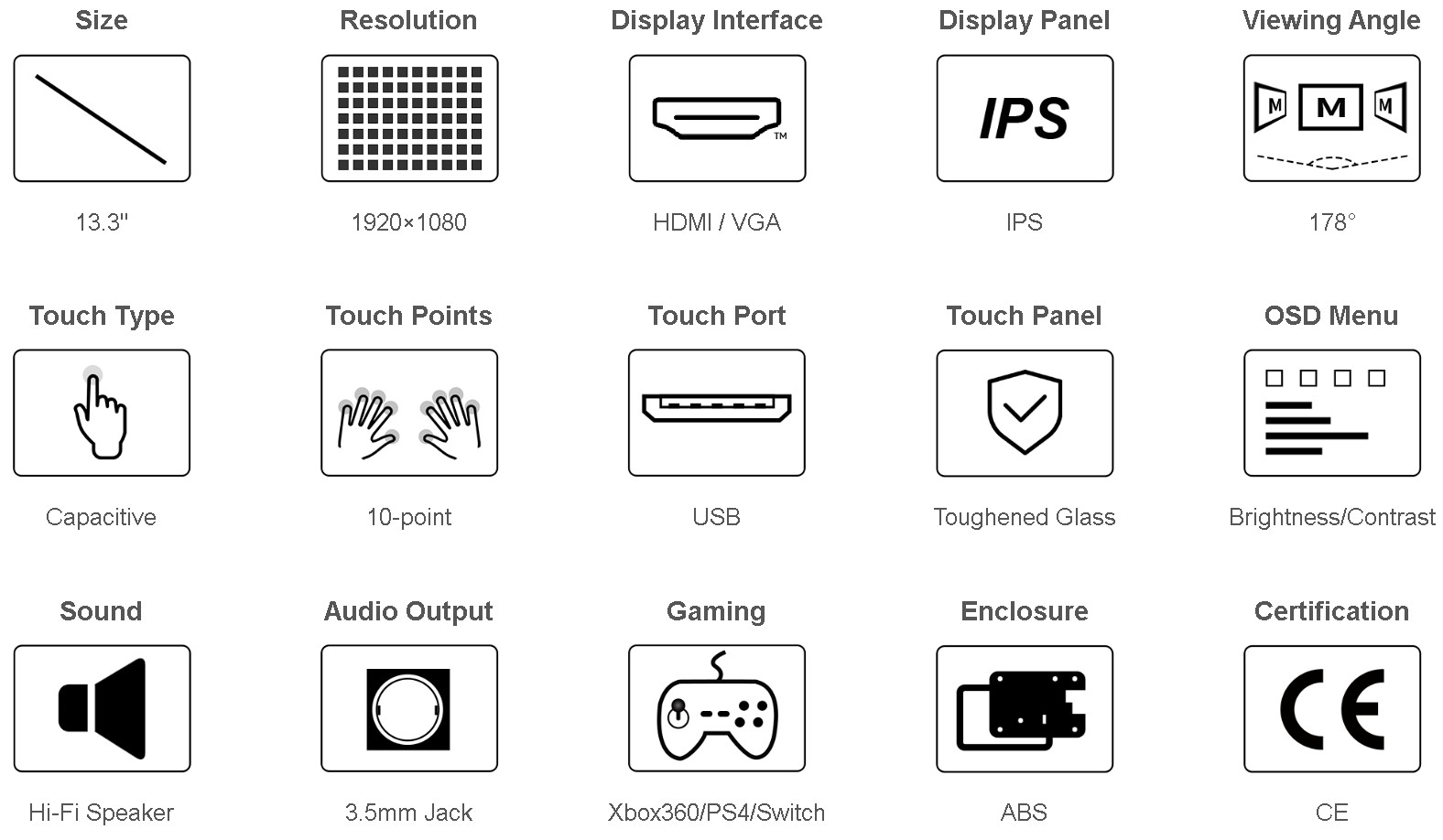
Features
- 13.3inch IPS screen,1920x1080 high resolution
- Toughened glass capacitive touch panel, 6H hardness
- Supports popular mini PCs such as Raspberry Pi, BB Black, as well as general desktop computers
- When works with Raspberry Pi, supports Raspbian, Ubuntu, WIN10 IOT, single touch, and driver free
- When work as a computer monitor, supports Windows 10/8.1/8/7, ten-points touch, and driver free
- Multi languages OSD menu, for power management, brightness/contrast adjustment, etc.
- 3.5mm audio jack, supports HDMI audio output
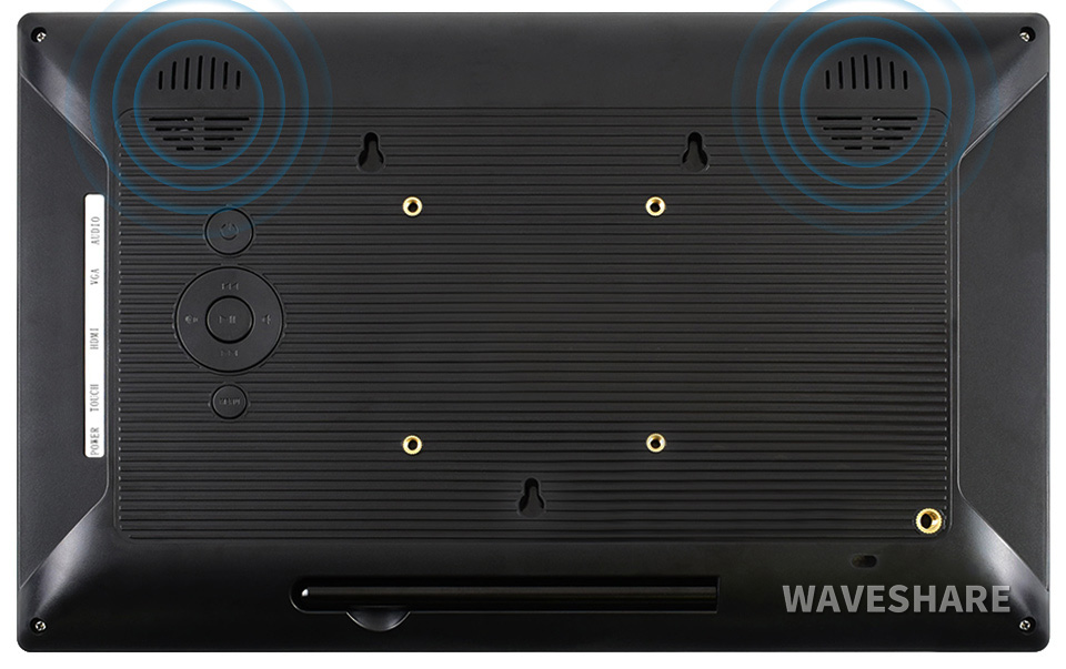
- Embedded ferrite Hi-Fi speaker
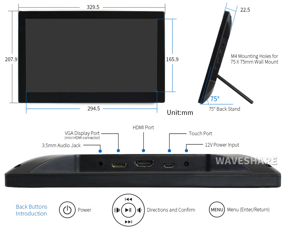
- Also supports VGA input (specific cable is required and should be purchased separately)
- 75x75mm spacing mounting holes (M4 screw hole) for general wall mount
- Comes with 75° tilt angle stand
Audio Features
![]()
Appearance and Dimensions
What's in the box?
1 x 13.3inch Capacitive Touch HDMI LCD
Resources
Wiki : www.waveshare.com/wiki/13.3inch_HDMI_LCD_(H)_(with_case)

Features
- Name: Arduino MEGA2560 R3 DIY acrylic case
- Dimensions: 118 x 72 x 18mm
- Weight: 72g
- Material: A level acrylic
- For Arduino MEGA2560 R3 Development Board only
Please Note: Arduino Mega is not included. Don't forget to remove the protective film from the acrylic parts.
What's in the box
1 x Transparent Acrylic case

Specifications
| Lead screw | |
| Material | stainless steel |
| Diameter | 8mm |
| Pitch | 2mm |
| Lead | 4 |
| Total Length | 400mm |
Screw nut | |
| Material | brass |
Diameter | 8mm |
| Pitch | 2mm |
| Lead | 4 |
Mounted ball bearing | |
| Material | zinc alloy |
| Bore diameter8 mm | 8mm |
| Total length | 55mm |
| Height | 29mm |
Shaft coupling | |
| Material | aluminium |
| Shaft | 6.35 x 8 mm |
| Length | 25 mm |
| Diameter | 20mm |
Motor | |
| Voltage | 24V |
| Step angle | 1.8° |
| Accuracy of step angle | ±5% |
| Accuracy of resistance | ±10% |
| Accuracy of inductance | ±20% |
| Insulation resistance | 100mΩmin 500VDC |
| Radial clearance | 0.02Max |
| Axial clearance | 0.08Max |
| Radial maximum tolerance | 28N |
| Axial maximum tolerance | 10N |
- 3D printer T8 400mm Stainless Steel Lead Screw Screw nut Mounted ball bearing Shaft coupling Motor.
- Screw mainly use for Stepping motor driving guide rail,machine tool, and other equipment.
- Screw without processing, direct connected to bearing.
- T shape design, make of high quality stainless steel material.
- Easy to install and convenient to use.
- Fine producing and practical.
- Suitable for Industrial automation equipment, stepper motor rails;
- Fit for 3D printer; engraving machine; XYZ module; slider; lifts ect.
What's in the box?

The GT2 belt clamp is used with open ended GT2 belt to form a loop. It is manufactured from Aluminium with a 2mm pitch and can be used with 6 and 9mm belts.
Features:
Best suitable for the synchronous belt of 2GT model
Specifications:
1. Size: 9x40mm
2. Material: aluminum
3. Teeth space: 1.1mm
4. Tooth width: 0.85mm
5. Tooth depth: 0.9mm
Package includes:
1 x Fixed Piece

- Using the ITR20001 Reflective Photoelectric Sensor
- Five ITR20001/T infrared light detectors are used with higher sensitivity, wider detection range and anti-interference.
- Five-channel analog output, higher accuracy, so that the tracking range of the car is wide and stable
Connection Reference:
VCC: Connect 3.3~5V
GND: Connect GND
U1: Connect MCU.IO(Channel, analog output)
U2: Connect MCU.IO(Channel, analog output)
U3: Connect MCU.IO(Channel, analog output)
U4: Connect MCU.IO(Channel, analog output)
U5: Connect MCU.IO(Channel, analog output)
Specifications:
Note:
*Please allow 1-3mm difference due to manual measurement.
Package Includes:
1 x Infrared Tracking Sensor

Power-up your TV with Picade Console! It's a compact, Raspberry Pi-powered retro games machine with authentic arcade controls that plugs right into your TV, monitor, or other HDMI display.
Picade Console is fight stick-style arcade console that riffs off our new Picade with the same retro feel, same joystick and buttons, dedicated power button, and driven by the same powerful combo of the Raspberry Pi and Picade X HAT. It's beautifully packaged, comes with stickers and a neon-infused A3 Picade Console poster, and full assembly instructions.
It comes in kit form and takes an hour or two to build. The enclosure is made from powder-coated MDF and acrylic, giving it an authentic arcade look and feel. All you'll need to add is a Raspberry Pi, power supply, HDMI cable, and micro-SD card.
*TV not included! Using a CRT TV requires additional adaptors.
Features
- Black, powder-coated panels
- Acrylic console with retro artwork
- Push-fit arcade buttons
- Joystick with black ball top
- Speaker (3W, 4Ω, 2.5" driver)
- Easy access with removable back panel
- Dedicated illuminated power button
- Grippy rubber feet
- Dimensions (assembled): 245x120x140mm
Picade X HAT features
- Easy DuPont connectors for buttons and joystick
- Push-fit speaker terminals
- I2S audio DAC with 3W amplifier (mono)
- Power management, power switch pins, and power button
- 4-way joystick inputs
- 6 player buttons
- 4 utility buttons
- Metal standoffs to hold your Picade X HAT securely
Extras
- Picade Console poster / assembly instructions
- Picade stickers
What's new?
Picade Console is more compact and easier to build, but has a bunch of new features liked a dedicated power button, better cable routing out the back of the console with a panel-mount micro-USB connector for power, and slick new artwork.
The new buttons in Picade are lower profile, and the new joystick has a single connector rather than the eight spade connectors on our previous Picade joystick.
Picade X HAT is all-new and packed full of useful features. We've moved from more fiddly screw terminals to simple DuPont connectors that just push in, and the speaker terminals are the same easy push-fit connectors that we use on pHAT BEAT.
There's dedicated power management on-board Picade X HAT; just plug your micro-USB power supply into the HAT and it'll power your Pi through its pins. The power button connected to the HAT means that once your Pi is safely shutdown, the power will be cut completely to the Pi. A simple press of the power button will boot your Picade Console up again.
Software setup
We recommend the RetroPie operating system for your Picade. You can download it from the RetroPie website and then burn it to a micro-SD card with Imager.
Connect a USB keyboard to your Pi, and connect to Wi-Fi in the RetroPie menu. Press F4 to exit to the terminal and then type curl https://get.pimoroni.com/picadehat | bash to run the Picade HAT installer.
Reboot your Pi, if it doesn't prompt you to. Press the "Alt" key on your keyboard and then select "Configure input" to configure your Picade Console's controls. You'll find that the sound and power button should both be working now too!
Where to find ROMs for RetroPie (free and legally) https://howchoo.com/g/otiwyjhlnzb/where-to-find-roms-for-retropie
and here http://cvaddict.com/article.php?articleid=15

Although the reader does not read the information on the NFC card, it is triggered by a 125 khz NFC card

Just slot in your micro:bit, then code automation:bit with the block-based Microsoft MakeCode editor. Hook up buttons to the inputs, use the built-in buttons on micro:bit, or the light-sensing capability of the LED matrix to control devices connected to automation:bit. Or why not use a second micro:bit's radio function as a remote control?
WARNING! automation:bit should not be used with voltages greater than 24V and especially not with mains voltages!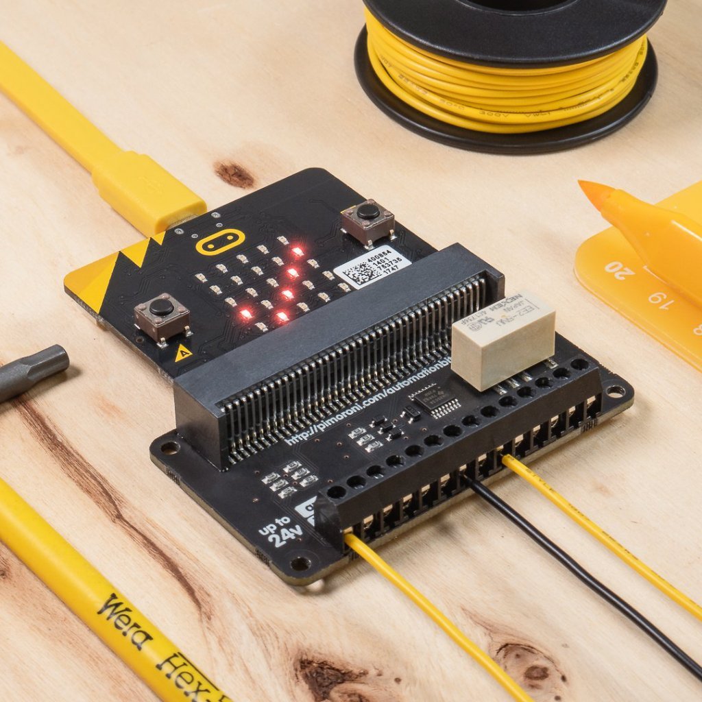
- Comes fully-assembled and ready to use
- 1 x 24V @ 2A relay (NC and NO terminals)
- 3 x ADC channels (0-24V range)
- 3 x 24V tolerant buffered inputs
- 3 x 24V tolerant sinking outputs
- 3.5mm screw terminals
- Compatible with micro:bit
- Microsoft MakeCode support
- No soldering required!
You can code automation:bit with the block-based Microsoft MakeCode editor, that'll get you started with using all of automation:bit's functionality.
To add the automation:bit library in MakeCode, click on the cog at the top right hand corner, then "Add Package", then enter the URL "https://github.com/pimoroni/pxt-automationbit". You can find full instructions at the GitHub repository for the library.
What's in the box?
1 x automation:bit