
Use a Pi Zero, Explorer pHAT and Zero LiPo to build a pretty firefly light
Special Offers

Explorer pHAT is the perfect prototyping side-kick for your Raspberry Pi!
Explorer pHAT (explorer phat)
Descrption:
Explorer pHAT is the perfect prototyping side-kick for your Raspberry Pi!
A more diminutive version of our popular Explorer Hat Pro, it's cheaper and designed to fit perfectly on a Raspberry Pi Zero!
We've added a heap of useful input and output options that will take your projects to the next level. Great for driving motors, using analog sensors, and interfacing with 5V systems (like Arduino).
Perfect for building a tiny robot, or use it to prototype all sorts of circuits with its LEDs, analog dials, and temperature sensor.
Features
- Four buffered 5V tolerant inputs (perfect for Arduino compatibility)
- Four powered 5V outputs (up to 500mA total across all four channels)
- Four analog inputs
- Two H-bridge motor drivers (up to 200mA per channel; soft PWM control)
- Compatible with Raspberry Pi 3, 2, B , A , and Zero
- Python library
- Female headers require soldering
Software
Explorer pHAT uses the same easy-to-use Python library as Explorer HAT Pro, that includes a bunch of examples to demonstrate Explorer pHAT's functions.
Notes
The inputs use a 5-channel buffer that will accept anything from 2V-5V as logic high.
Tutorials & Projects
Build a firefly light
Explorer pHAT is the perfect prototyping side-kick for your Raspberry Pi!

Crocodile Clips with Male USB Connector Test Lead (USB crocodile clips)
This testing wire with alligator clips will help transmit DC current to other multi-meters or other usage.
Made from copper wire and well-made PVC.
It can pass 3-5A(max) current during your testing work.
High performance, lower resistivity and durable, fast and stable, high-speed output current
Specifications
- Colour: Red and Black (V and V-)
- Power: 5V
- Working current: 3-5A
- Lines size: 2x18AWG
- Cable Length: 332mm
What's in the box?
1 x USB Male Alligator test lead

GT2 Synchronous Wheel 5MM With 20 Teeth 20-5-6 T Silver (GT2 wheel 5mm teeth)
Item specs:
Material: Alloy
Type: Timing
Model: With 20 teeth
Bore: 5mm
For belt: 6mm
Package Includes:
1 x GT2 Synchronous Wheel 5MM With 20 Teeth

Adafruit PiTFT Plus 320x240 2.8" TFT Capacitive Touchscreen(40 pin) (2.8 display touch cap 40pin)
Description:
Is this not the cutest little display for the Raspberry Pi? It features a 2.8" display with 320x240 16-bit color pixels and a capacitive touch overlay. That's right, instead of a resistive touchscreen, which requires a fingernail or stylus, you can now use a fingerpad.
The screen looks much nicer, with a black bezel and glass overlay.
This updated design fits perfectly onto the Pi Zero, Pi 3, Pi 2 or Model A , B ! (Any Pi with a 2x20 connector) Not for use with an old Pi 1 with 2x13 connector. This version also has all 40 pins GPIO pins brought out so you can connect a 40-pin GPIO cable underneath.
The display and touchscreen uses the hardware I2C Pins (SDA & SCL), SPI pins (SCK, MOSI, MISO, CE0) as well as GPIO #25 and #24. All other GPIO are unused and you can still share the I2C pins with sensors, LED drivers, etc. Since we had a tiny bit of space, there's 4 slim tactile switches wired to four GPIOs, that you can use if you want to make a basic user interface. For example, you can use one as a power on/off button.
Use it for console access or easily pop up X11 onto the PiTFT for a mini monitor, although its rather small at 320x240. Instead, we recommend using PyGame or other SDL-drawing programs to write onto the frame buffer.
Raspberry Pi computer and enclosure not included! As of July 22nd, 2015 this display comes fully assembled with tactile switches too
TECHNICAL DETAILS
- Screen Dimensions: 50mm x 69mm x 4mm / 2" x 2.7" x 0.16"
- PCB Dimensions: 56mm x 85mm x 11mm / 2.2" x 3.3" x 0.4"
- Weight: 47g
Datasheets, EagleCAD PCB files, Fritzing object and more in the tutorial!

T8 300mm Lead Screw Rod Coupler Bearing Block For Stepper Motor (T8 300mm lead screw cnc kit)
A leadscrew (or lead screw), also known as a power screw or translation screw, is a screw used as a linkage in a machine, to translate turning motion into linear motion. Widely used in CNC machines, and 3D printers.
Features
- Two bearing block stability greatly improved.
- 304 Stainless steel has excellent corrosion resistance and good resistance to intergranular corrosion.
Specifications
Fit For: Stepper Motor
Colour: Silver gold
Materials: 304 stainless steel brass
Size: 300mm x 8mm
Lead Rod: 8mm
What's in the box?
1 x Lead screw rod
1 x Nut
2 x Coupling
2 x Bearing seat

V6 J-Head Metal Hot End Fixed Bracket For RepRap 3D Printer Extruder (extruder bracket)
Description:
Use box-type bearing module, the maximum extent to ensure the stability of operation of the print head, while ensuring stability in the premise, as far as possible to simplify the design and reduce the weight of the printhead mounting base on the maximum.
Aluminum alloy, surface sandblasting treatment, more texture.
Suitable for Reprap Prusa i3 3D printers use, shaft pitch can be adjusted to ensure suitability mounting base and prints.
After sandblasting surface treatment products more attractive, scratch-resistant.
Specifications:
Type: E3D V6
Material: Metal
Bracket Width: 35.6mm
Holder Height: 50mm
Holder Depth: 33.6mm
Fit for: 3D Printer Extruder
Package Includes:
1x E3D V6 Bracket

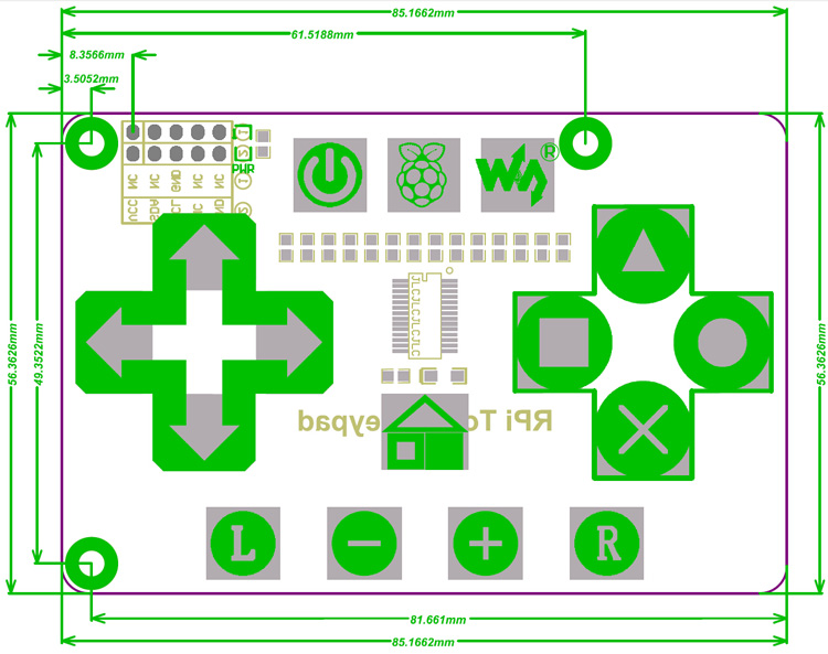
RPi Touch Keypad (RPi touch pad hat)
Features
Downloads/Development resources:
schematic, demo code, datasheets, etc.
Download: www.waveshare.com/wiki/RPi_Touch_Keypad
- Supports any revision of Raspberry Pi (directly-pluggable)
- Provides your Pi with 16 touch keys
- Features TONTEK TonTouch touch pad detector IC TTP229-LSF, supports up to 16 keys with adjustable sensitivity and built-in LDO
- The system re-calibrates automatically when all keys are not detected touch more than about 4 seconds
- Interface : I2C
- Keys : 16
- Sampling rate : 8Hz
- Human Body Mode : 6KV
- Operating voltage : 2.4V-5.5V
- Operating temperature : -40℃ to 85℃
- Storage temperature : -50℃ to 125℃
- Dimensions : 8.5CM × 5.6CM
- After power-on have about 0.5sec stable-time. During the time do not touch the key pad, and all functions are disabled
- VCC : Power supply (2.4V-5.5V)
- GND : Ground
- SDA : I2C SDA
- SCL : I2C SCL
Downloads/Development resources:
schematic, demo code, datasheets, etc.
Download: www.waveshare.com/wiki/RPi_Touch_Keypad

RFID Classic 125 khz EM4100/TK4100 watch Silicone Wristband (125khz rfid wrist band)
Whilst being completely portable and convenient, RFID Wristbands give you the freedom to express your business in the way you want to. You can choose not only an enjoyable accessory but an invaluable tool to your organisation.
Typical Application
Specifications
What's in the box?
1 x RFID wristband
Typical Application
Access control for events, concerts, clubs.
Tracking for sports.
Membership management for heath care, childcare, and so on.
- Frequency: 125KHz
- Standard: ISO EM4100 and compatible
- Material: Silicone (100% SGS approved, RoHS, eco-friendly)
- Printing: no logo
What's in the box?
1 x RFID wristband

LCD Keypad Shield LCD1602 LCD 1602 Module Display For Arduino ATMEGA328 ATMEGA2560 raspberry pi UNO blue screen (buttons blue backlight)
Features
What's in the box?
1 X Keypad Shield 1602 LCD
Resources
DFRobot WIKI
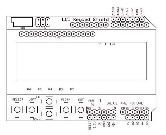
- This is a basic 16 character by 2 line display.
- Utilizes the extremely common HD44780 parallel interface chipset.
- Interface code is freely available.
- Blue Backlight with white words.
- uses 4 Bit Arduino LCD Library.
- Size:8cm x 5.9cm - 3.15inch x 2.32inch
What's in the box?
1 X Keypad Shield 1602 LCD
Resources
DFRobot WIKI

Adafruit 12-Bit DAC w/I2C Interface (MCP4725) (AdaMCP4725 DAC)
Your microcontroller probably has an ADC (analog -> digital converter) but does it have a DAC (digital -> analog converter)??? Now it can! This breakout board features the easy-to-use MCP4725 12-bit DAC. Control it via I2C and send it the value you want it to output, and the VOUT pin will have it. Great for audio / analog projects, such as when you can't use PWM but need a sine wave or adjustable bias point.
What's in the box?
1 x Adafruit MCP4725
The ADDR pin is broken out so you can connect two of these DACs on one I2C bus, just tie the ADDR pin of one high to keep it from conflicting. Also included is a 6-pin header, for use in a breadboard. Works with both 3.3V or 5V logic.
Some nice extras with this chip: for chips that have 3.4Mbps Fast Mode I2C (Arduino's don't) you can update the Vout at ~200 KHz. There's an EEPROM so if you write the output voltage, you can 'store it' so if the device is power cycled it will restore that voltage. The output voltage is rail-to-rail and proportional to the power pin so if you run it from 3.3V, the output range is 0-3.3V. If you run it from 5V the output range is 0-5V.
Adafruit have an easy-to-use Arduino library and tutorial with a triangle-wave and sine-wave output example that can be used with any 'duino or ported to any microcontroller with I2C host. Wiring it up is easy - connect VDD to your microcontroller power pin (3-5V), GND to ground, SDA to I2C Data (on the Arduino Uno, this is A4 on the Mega it is 20 and on the Leonardo digital 2), SCL to I2C Clock(on the Arduino Uno, this is A5 on the Mega it is 21 and on the Leonardo digital 3) and listen on VOUT.
TECHNICAL DETAILS
- Datasheet, Fritzing, and EagleCAD PCB files available in the product tutorial
- This board/chip uses I2C 7-bit address between 0x62-0x63, selectable with jumpers
What's in the box?
1 x Adafruit MCP4725

LilyPad Power Supply Module AAA Battery Step up to 5V Converter (wearable AAA battery holder)
A small, but mighty power supply. This board was designed to be as small and inconspicuous as possible. Pop in a AAA battery, flip the power switch, and you will have a 5V supply to power your LilyPad circuit. Good up to 200mA. Short circuit protected.
This board has AAA battery clips but can use an input from 1.2V to 5V.
LilyPad is a wearable e-textile technology developed by Leah Buechley and cooperatively designed by Leah and SparkFun. Each LilyPad was creatively designed to have large connecting pads to allow them to be sewn into clothing. Various input, output, power, and sensor boards are available. They're even washable - but be sure to remove the battery!
What's in the box?
1 x LilyPad Power Supply Converter Module AAA Battery Step up to 5V
Need batteries? You will find our battery selection here

DC 5V WCS1800 Hall Current Detection Sensor Module 35A Precise With Overcurrent Signal LED (WCS1800 Hall Current)
The WCS1800 Hall Current sensor has two functions
Features
What's in the box?
1 x WCS1800 Hall current detection sensor
Resources
Interface
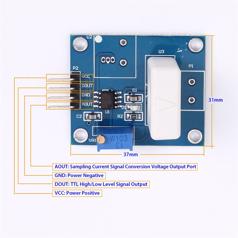
VCC: power positive
DOUT: TLL high/low level signal output
GND: power negative
AOUT: sampling current signal conversion voltage output port
Analog voltage signal output (AOUT)
Relationship between detection current and analog signal output is shown below:
Analog signal output: V0=Vcc*0.5±la*K (la is actual current through current detection pin, and K is linearity)
Eg: Input current is 1A, Vcc=5V and WS1800 linearity is 60mV/A
The above are ideal values. There might be some precision errors.
On/Off output(DOUT)
- current detection
- over current protection (can be preset from 0.5A to 35.0A)
Features
- Operating voltage: DC 5V
- Current detection range: DC +-35A, AC 25A
- Linearity: K=60mV/A
- Limit current range: 0.5A to 35A(for on/off value output)
- Over current signal indicator LED
- Sampling current conversion analog voltage signal output and it can connect ADC; TTL level signal output and it can connect MCU IO port control
- Board size 37mm x 31mm
- Working temperature: 25 to 85C
What's in the box?
1 x WCS1800 Hall current detection sensor
Resources
Interface
VCC: power positive
DOUT: TLL high/low level signal output
GND: power negative
AOUT: sampling current signal conversion voltage output port
Analog voltage signal output (AOUT)
Relationship between detection current and analog signal output is shown below:
Analog signal output: V0=Vcc*0.5±la*K (la is actual current through current detection pin, and K is linearity)
Eg: Input current is 1A, Vcc=5V and WS1800 linearity is 60mV/A
- When the current flows in from positive direction: V0=Vcc*0.5+la*K, V0=(2.5+0.06)V=2.56V
- When the current flows in from negative direction: V0=Vcc*0.5-la*K, V0=(2.5-0.06)V=2.44V
- If it is an AC signal: V0=Vcc*0.5+la*K, V0=(2.5+0.06)V=2.56V
The above are ideal values. There might be some precision errors.
On/Off output(DOUT)
- Make sure the current flows in from the positive direction. Adjust to the desired current warning level.
- LED will be on when current is below the setting and DOUT will be low.
- When the detected current is higher than your setting, the LED will turn off and the DOUT pin will go high.

PUD Board (Pull-Up/Down Resistor Board) (MMP PUD board)
What's in the box:
1 x PUD Board
RASPBERRY PI BOARD NOT INCLUDED
Description:
Whether you're pulling-up or pulling-down, there's no need to frown! With the PUD board from ModMyPi, adding multiple pull-up or pull-down resistors to your Raspberry Pi project is easy!
If you want to detect an "output" with your Raspberry Pi, like a button being pressed or a motion sensor detecting movement, we can configure our Raspberry Pi's GPIO pin as an "input". That input pin can be in three states (known as Tri-State logic); "high", when 3.3V is applied, "low", when the pin is connected to 0V, and "floating" when the state is undefined. Floating voltages are troublesome in electronics as the input can either read high or low depending on various fluctuations in electrical noise. Like a gate flapping open and closed in the wind, someone needs to lock the gate closed, or wedge it open. If you leave it flapping, it's likely to hit someone on their bottom on the way through!
Like our gate, the best way to avoid a floating input is to "tie" your input pin either high or low to create a default state. This is usually achieved through the use of a pull-up or pull-down resistor, either connecting our input pin via a resistor to the Pi's 3.3V to achieve a 3.3V high state, or the GND line to achieve 0V low state.
Our PUD board takes the messy wiring out of adding a pull-up or pull-down resistor to your circuit. Simply wire up the sensor output to the single pin on the PUD board and add a shunt jumper to either pull up (u) or down (d)! Therefore when you apply a signal voltage from your sensor or switch, the Pi is easily able to sense into which logic state the pin has been pulled! No more trouble from floating I/O's!
The PUD boards connects across GPIO pins 11 to 18 (17 to 24 in BCM speak), and adds a jumper configurable pull-up or pull-down resistor to each GPIO pin: 11 (BCM 17), 12 (BCM 18), 13 (BCM 27), 15 (BCM 22), 16 (BCM 23) and 18 (BCM 24). Pin 17 (3.3V) & pin 14 (GND) are used to tie the pins!
The PUD Board Features:
- Add a pull-up or pull-down resistor to your GPIO with the swap of a jumper!
- Compatible with all Raspberry Pi Models Inc. A /B /2/3 & Zero/ZeroW
- Tiny board means it's easy to integrate into any circuit - takes up just 8 GPIO pins
- Connects across GPIO pins 11 to 18 inclusive (BCM 17 to 24)
- In-line 1kΩ current limiting resistors on each GPIO
- 10kΩ pull-up or pull-down resistors on each GPIO
- All 6 GPIO pins can be configured independently
- Includes 6 x 2 Pin Shunt Jumpers & 1 x PUD Board
- Jumper configurable pull-up or pull-down resistor on pins:
- 11 (BCM 17)
- 12 (BCM 18)
- 13 (BCM 27)
- 15 (BCM 22)
- 16 (BCM 23)
- 18 (BCM 24).
- Pin 17 (3.3V) & Pin 14 (GND) are used to tie the pins!
- To pull pin up, connect the jumper across "u" and the center pin
- To pull pin down, connect the jumper across "d" and the center pin
What's in the box:
1 x PUD Board
Tutorials:

Learning to solder LED kit Pack of 25 (KT begin solder bundle)
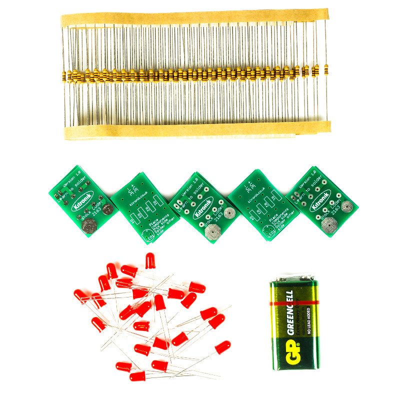
Our learn to solder pack is the ideal low cost solution for teaching soldering in the classroom/after school club. The pack provides all of the parts and PCB's required for a class size of 25 and also includes a 9V battery for testing purposes. Each pack comprises; 25 x PCBs, 100 x 100 ohm resistors, 25 x LED's, and a 9V PP3 battery.
We have also produced a step by step guide to soldering, which covers; equipment, solder, tinning & cleaning, soldering in 8 steps, de-soldering in five steps, wire preparation, examples of good and bad solder joints, basic PCB repair, resistor information, LED information, full step by step build information for the kit, and how the learn to solder kit works. This guide covers everything that you might need to discuss with students and can form the basis of your lesson plan.
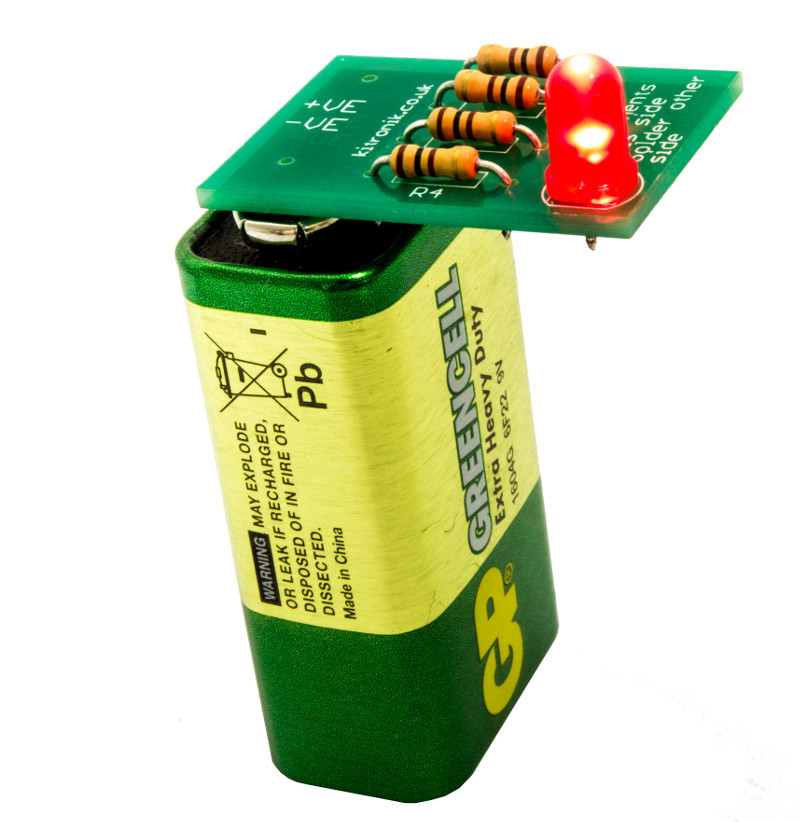
Using the kits and the step by step guide, each student will solder four resistors and one LED to their PCB before pressing it to the terminals of the 9V battery to check that their board works. Using the guides they will be able to examine their own work and troubleshoot problems. The battery pads on the PCBs have been shaped inline with the battery terminals on a PP3 battery making it straightforward to see which way around it should be placed on the battery.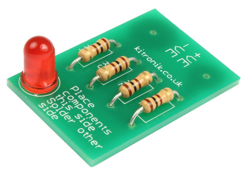
Features
- Purpose built PCBs that can be tested, once built, with the supplied 9V PP3 battery.
- Low cost classroom pack for 25 students.
- Easy build kit.
- Full teaching resources and step by step guides available for this kit below.
What's in the box?
100 x 100 ohm Resistors.
25 x Red 5mm Diffused LED - 275mCd.
25 x Learn To Solder PCBs.
1 x 9V Zinc Chloride PP3 Battery.
Dimensions
- Built Height: 11mm.
- PCB Length: 31mm.
- PCB Width: 21mm.
- PCB Height: 1.5mm.

Electro-Fashion Starter Pack, Standard Cell Holder (Fashion Starter Pack)
Product description:
This pack is a great way to get started with E-Textiles.
We have selected a number of products from our Electro-Fashion range, including three of our ultra-slim LEDs and two seperate power boards. There are enough components for you get started immediately to create some eye catching E-Textiles projects, the only limit is your imagination.
Features:
- Everything you need to complete two projects.
- Enough Electro-Fashion components to get started immediately with E-Textiles.
- Full instructions for assembly.
- Great project ideas and tutorials.
Contents:
- 2 x Coin Cell Holder.
- 3 x Sewable LEDs White.
- 3 x Flashing LEDs White.
- 1 x Slide Switch.
- 1 x Push Switch.
- 2 x CR2032 Coin Cell Batteries.
- 1 x 6m Conductive Thread.
Dimensions:
- Sewable Coin Cell Holder Length: 34mm.
- Sewable Coin Cell Holder Width: 20mm.
- Sewable Coin Cell Holder Height: 4.5mm.
- Ultra Slim Sewable LED Length: 15mm.
- Ultra Slim Sewable LED Width: 6.5mm.
- Ultra Slim Sewable LED Height: 2.7mm.
- Slide Switch Length: 18mm.
- Slide Switch Width: 8.5mm.
- Slide Button Switch Height: 4mm.
- Push Button Switch Length: 18mm.
- Push Button Switch Width: 8.5mm.
- Push Button Switch Height: 3mm.
- CR2032 Battery Height: 3.2mm.
- CR2032 Battery Diameter: 20mm.
Requires:
- Scissors.
- Needles.
Resources:
Caution:
- The coin cell holders in this pack contain Nickel and should not be used in designs where it will be in prolonged contact with the skin.

WS 5inch HDMI LCD Bi-colour case for Raspberry Pi (5 inch display and bi-colour case)
Please Note: Raspberry Pi not included.
5 inch Resistive Touch Screen LCD, HDMI interface, Designed for Raspberry Pi. Mid-sized Raspberry Pi or SBC 5 Inch Touch LCD with HDMI interface! Especially useful for those smaller embedded projects, such as adding LCD control to CNCs or 3D printers.
Specifications
The LCD
The Case
Resources

5 inch Resistive Touch Screen LCD, HDMI interface, Designed for Raspberry Pi. Mid-sized Raspberry Pi or SBC 5 Inch Touch LCD with HDMI interface! Especially useful for those smaller embedded projects, such as adding LCD control to CNCs or 3D printers.
Specifications
The LCD
- 800×480 high resolution, touch control
- Compatible and Direct-connect with any revision of Raspberry Pi (except the Pi 1 model B or Pi Zero, which requires an HDMI cable)
- Drivers provided (works with your own Raspbian/Ubuntu directly)
- HDMI interface for displaying, no I/Os required (however, the touch panel still needs I/Os)
- Backlight can be turned off to lower power consumption
- High quality immersion gold surface plating
The Case
- Material : high quality bicolor Acrylic, black and white
- Comes with bottom holder, optional tilt angle, 45° or 60°
- Features mounting holes for Raspberry Pi A /B /2B/3B
What's in the box?
1 x 5inch HDMI LCD
1 x HDMI connector
1 x Touch pen
1 x RPi screws pack (4pcs)
1 x Bicolor Case for 5inch LCD
1 x Screws Pack
1 x HDMI connector
1 x Touch pen
1 x RPi screws pack (4pcs)
1 x Bicolor Case for 5inch LCD
1 x Screws Pack
Resources
How to install: instructions
Wiki : www.waveshare.com/wiki/5inch_HDMI_LCD

CamJam EduKit 2 - Sensors (CamJam EduKit #2)
The CamJam EduKit #2 is the second edition to the EduKit family!
The kit is accompanied by a set of (currently 6) downloadable worksheets (or lesson plans for you educators!) that will take you through a series of exercises and projects, teaching you how to make the most of your kit. Whats best is that there is no soldering required, each high quality component is breadboard friendly!
All the worksheets are freely available to download from http://camjam.me/edukit
What's in the box?
1 x Breadboard
1 x Immersible temperature Sensor
1 x PIR Sensor
1 x LDR
1 x Active Buzzer
1 x Red 10mm LED
1 x Blue 10mm LED
1 x 4.7K Resistor
2 x 330 Resistor
10 x M/F Jumper Wires
4 x M/M Jumper Wires
1 x Presentation Tin
Resources
Here are just 4 cool projects you could use the kit for:
- Make a burglar alarm for your bedroom.
- Switch on an LED when it gets dark.
- Have an alarm go off when it’s freezing outside.
- Test whether the light really does go off in the fridge when you shut the door.
Still not convinced? Check out these awesome articles on the kit!
- "CamJam Edukit 2 Launches at PiWars" - Raspi.tv
- "The CamJam EduKit 2 - Learn How To Use Sensors With The Raspberry Pi" - Average Man vs Raspberry Pi
The CamJam EduKit is a joint venture between The Pi Hut and the Cambridge Raspberry Jam (CamJam). Profits from the sale of the kit will go to CamJam so that they can continue their educational and community work.

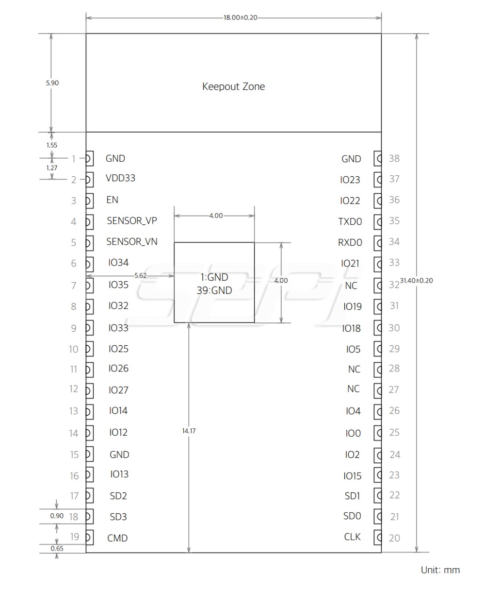
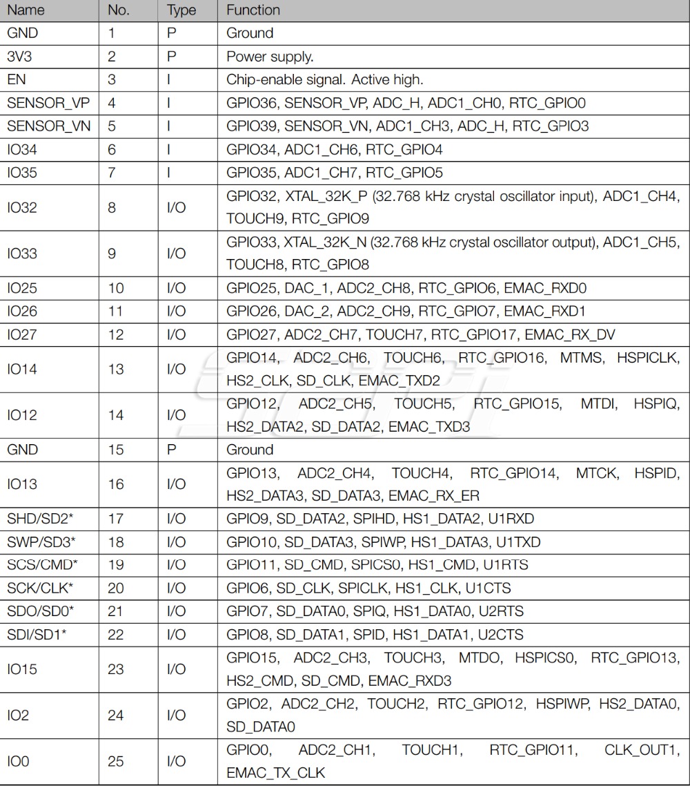
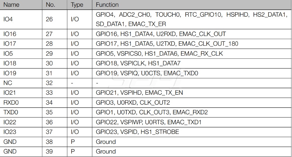
ESP32-WROVER 4MB Module with Bluetooth and WiFi (ESP32-WROVER)
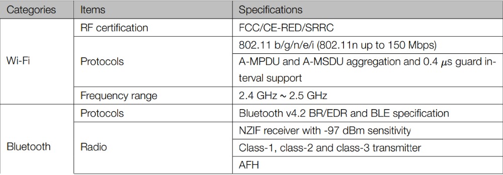
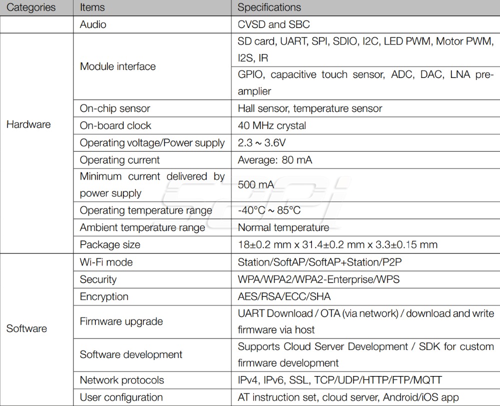
ESP32-WROVER is a powerful, generic WiFi-BT-BLE MCU module that targets a wide variety of applications, ranging from low-power sensor networks to the most demanding tasks, such as voice encoding, music streaming and MP3 decoding. At the core of this module is the ESP32-D0WDQ6 chip*, same as ESP-WROOM-32 module. Compared to ESPWROOM-32, ESP32-WROVER has an additional SPI Pseudo static RAM (PSRAM) of 32 Mbits. As such, ESP32- WROVER features both 4 MB external SPI flash and 4 MB external PSRAM. The ESP32-WROVER module has a PCB antenna, while the ESP32-WROVER-I uses an IPEX antenna. The information in this datasheet is applicable to both of the two modules. The chip embedded is designed to be scalable and adaptive. There are two CPU cores that can be individually controlled, and the clock frequency is adjustable from 80 MHz to 240 MHz. The user may also power off the CPU and make use of the low-power coprocessor to constantly monitor the peripherals for changes or crossing of thresholds. ESP32 integrates a rich set of peripherals, ranging from capacitive touch sensors, Hall sensors, low-noise sense amplifiers, SD card interface, Ethernet, high-speed SPI, UART, I2S and I2C.
The integration of Bluetooth, Bluetooth LE and Wi-Fi ensures that a wide range of applications can be targeted, and that the module is future proof: using Wi-Fi allows a large physical range and direct connection to the internet through a Wi-Fi router, while using Bluetooth allows the user to conveniently connect to the phone or broadcast low energy beacons for its detection. The sleep current of the ESP32 chip is less than 5 µA, making it suitable for battery powered and wearable electronics applications. ESP32 supports a data rate of up to 150 Mbps, and 22 dBm output power at the antenna to ensure the widest physical range. As such the chip does offer industry-leading specifications and the best performance for electronic integration, range, power consumption, and connectivity. The operating system chosen for ESP32 is freeRTOS with LwIP; TLS 1.2 with hardware acceleration is built in as well. Secure (encrypted) over the air (OTA) upgrade is also supported, so that developers can continually upgrade their products even after their release.
What's in the box?
1 x ESP32-WROVER 4MB Module
Resources

GY-302 BH1750 BH1750FVI light intensity illumination module 3V-5V (light intensity sensor board)
For a wide range of brightness for 1 lux high precision measurement.
This sensor module is the most suitable to receive the ambient light data for adjusting LCD and other related projects. It is possible to detect wide range at High resolution.
The sensor is a calibrated digital light sensor that measures the intensity of the ambient light and stores it as a 16-bit number.
Specifications
What's in the box?
1 x GY-302 Module
This sensor module is the most suitable to receive the ambient light data for adjusting LCD and other related projects. It is possible to detect wide range at High resolution.
The sensor is a calibrated digital light sensor that measures the intensity of the ambient light and stores it as a 16-bit number.
Specifications
- Type: GY - 302
- Size: 13.9 mm X 18.5 mm
- The original BH1750FVI ROHM chip
- Power supply: 3-5 V
- Data range: 0-65535
- Sensor built-in and bitad converter
- Direct digital output, bypassing the complicated calculation, omit calibration
- Do not distinguish between ambient light
- Close to the visual sensitivity of spectral characteristics
What's in the box?
1 x GY-302 Module

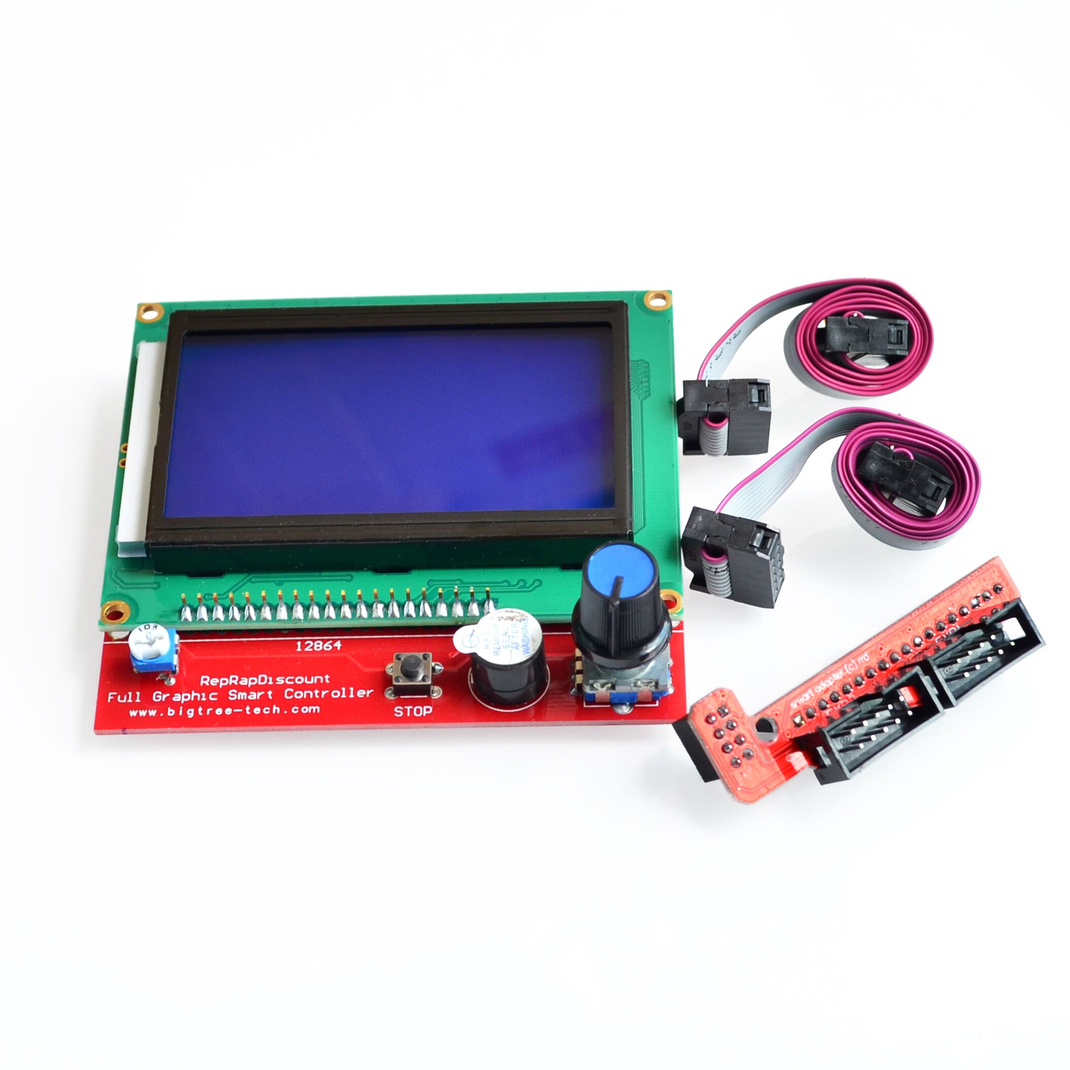
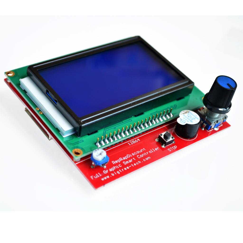
Full Graphic 12864 Smart Controller RAMPS 1.4 LCD 12864 LCD Control Panel Blue Screen for 3D Printer (12864 3d printer display)
Description:
LCD control panel for 3D printers. LCD control panel through which you can achieve spooling as the 3D model Gcode files are copied to the SD card and then print the file via the LCD control panel. This version is an upgraded version of the reprap smart controller.
Features:
Using a large screen 12864LCD
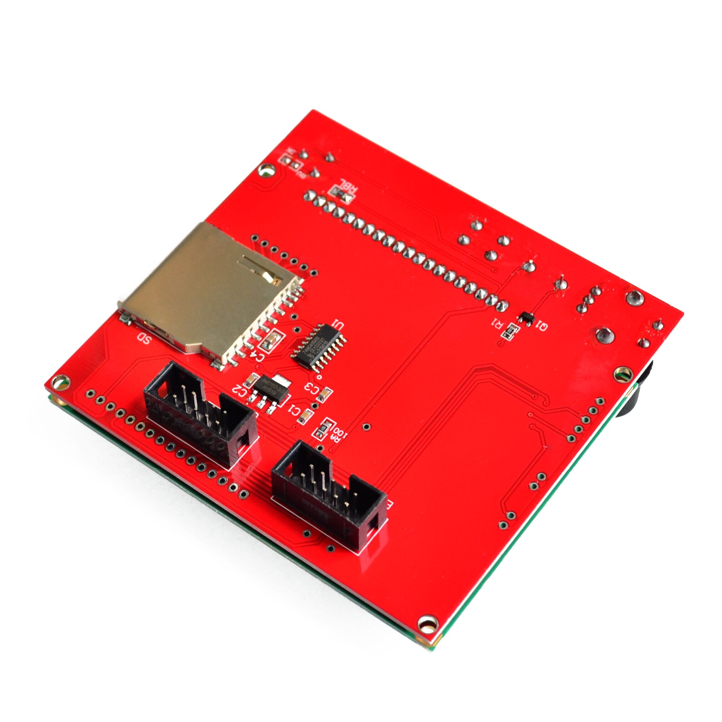
With a SD card base on back, put your sliced file onto the SD card and select the file on the LCD. It can then can be printed
Product comes encoder to select the desired file
Plug and play on the RAMPS, but may need to modify the firmware to support
Specifications:
Screen size: 128x64
Cable Length (cm): 30
Input Supply Voltage: (VDC) 5
Length (mm): 93
Width (mm): 87
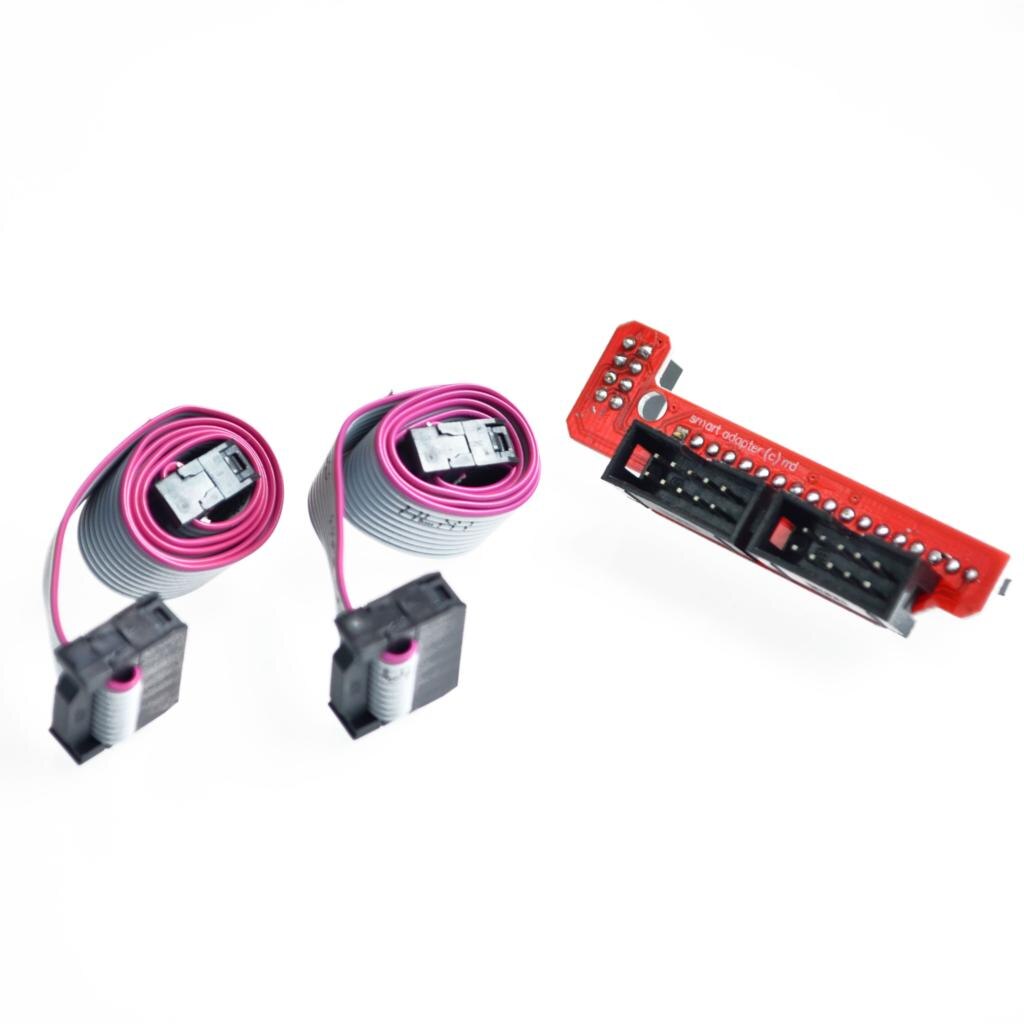
Package Includes:
1x LCD 12864 Smart Controller
1x Smart Adapter
2x 30cm FC Cable
LCD control panel for 3D printers. LCD control panel through which you can achieve spooling as the 3D model Gcode files are copied to the SD card and then print the file via the LCD control panel. This version is an upgraded version of the reprap smart controller.
Features:
Using a large screen 12864LCD
With a SD card base on back, put your sliced file onto the SD card and select the file on the LCD. It can then can be printed
Product comes encoder to select the desired file
Plug and play on the RAMPS, but may need to modify the firmware to support
Specifications:
Screen size: 128x64
Cable Length (cm): 30
Input Supply Voltage: (VDC) 5
Length (mm): 93
Width (mm): 87
Package Includes:
1x LCD 12864 Smart Controller
1x Smart Adapter
2x 30cm FC Cable