
Special Offers

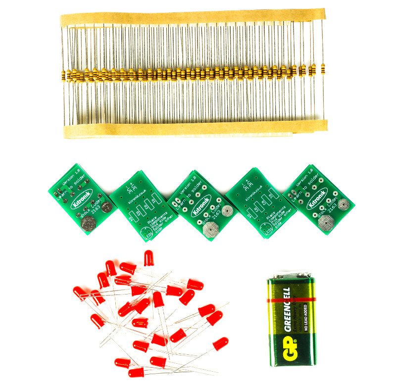
Our learn to solder pack is the ideal low cost solution for teaching soldering in the classroom/after school club. The pack provides all of the parts and PCB's required for a class size of 25 and also includes a 9V battery for testing purposes. Each pack comprises; 25 x PCBs, 100 x 100 ohm resistors, 25 x LED's, and a 9V PP3 battery.
We have also produced a step by step guide to soldering, which covers; equipment, solder, tinning & cleaning, soldering in 8 steps, de-soldering in five steps, wire preparation, examples of good and bad solder joints, basic PCB repair, resistor information, LED information, full step by step build information for the kit, and how the learn to solder kit works. This guide covers everything that you might need to discuss with students and can form the basis of your lesson plan.
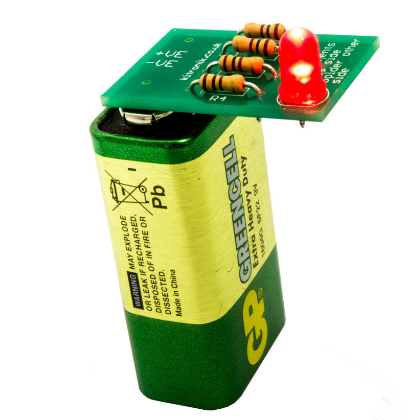
Using the kits and the step by step guide, each student will solder four resistors and one LED to their PCB before pressing it to the terminals of the 9V battery to check that their board works. Using the guides they will be able to examine their own work and troubleshoot problems. The battery pads on the PCBs have been shaped inline with the battery terminals on a PP3 battery making it straightforward to see which way around it should be placed on the battery.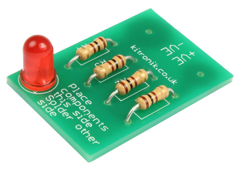
Features
- Purpose built PCBs that can be tested, once built, with the supplied 9V PP3 battery.
- Low cost classroom pack for 25 students.
- Easy build kit.
- Full teaching resources and step by step guides available for this kit below.
What's in the box?
100 x 100 ohm Resistors.
25 x Red 5mm Diffused LED - 275mCd.
25 x Learn To Solder PCBs.
1 x 9V Zinc Chloride PP3 Battery.
Dimensions
- Built Height: 11mm.
- PCB Length: 31mm.
- PCB Width: 21mm.
- PCB Height: 1.5mm.

This pack is a great way to get started with E-Textiles.
We have selected a number of products from our Electro-Fashion range, including three of our ultra-slim LEDs and two seperate power boards. There are enough components for you get started immediately to create some eye catching E-Textiles projects, the only limit is your imagination.
Features:
- Everything you need to complete two projects.
- Enough Electro-Fashion components to get started immediately with E-Textiles.
- Full instructions for assembly.
- Great project ideas and tutorials.
Contents:
- 2 x Coin Cell Holder.
- 3 x Sewable LEDs White.
- 3 x Flashing LEDs White.
- 1 x Slide Switch.
- 1 x Push Switch.
- 2 x CR2032 Coin Cell Batteries.
- 1 x 6m Conductive Thread.
Dimensions:
- Sewable Coin Cell Holder Length: 34mm.
- Sewable Coin Cell Holder Width: 20mm.
- Sewable Coin Cell Holder Height: 4.5mm.
- Ultra Slim Sewable LED Length: 15mm.
- Ultra Slim Sewable LED Width: 6.5mm.
- Ultra Slim Sewable LED Height: 2.7mm.
- Slide Switch Length: 18mm.
- Slide Switch Width: 8.5mm.
- Slide Button Switch Height: 4mm.
- Push Button Switch Length: 18mm.
- Push Button Switch Width: 8.5mm.
- Push Button Switch Height: 3mm.
- CR2032 Battery Height: 3.2mm.
- CR2032 Battery Diameter: 20mm.
Requires:
- Scissors.
- Needles.
Resources:
Caution:
- The coin cell holders in this pack contain Nickel and should not be used in designs where it will be in prolonged contact with the skin.

Pibow Coupé 4. The slim, hackable, and attractive case for the Raspberry Pi 4!
Note: This Pibow Coupé is only compatible with the Raspberry Pi 4!
Features
- Compatible with Raspberry Pi 4 only
- Cutout in lid for 40x30mm heatsink or Fan SHIM
- Super-slimline profile
- Fully HAT-compatible
- Works great with standoffs!
- Protects your beloved Pi!
- Clear top and base (Ninja and Red) leave Raspberry Pi 4 visible
- GPIO cut-out
- Handy laser-etched port labels
- Leaves all ports accessible
- Made from lightweight, high-quality, cast acrylic
- Great for hacking and tinkering!
- Made in Sheffield, UK
Crafted out of five unique layers including a transparent top and base (Red and Ninja) that leave your beautiful Raspberry Pi 4 visible inside. Each layer is laser-cut from colourful, high-quality, cast acrylic and once stacked they securely contain a Raspberry Pi 4 while leaving the primary ports, including the camera port, display port, and GPIO accessible.
Weighing just over 50 grams, the case is lightweight and ideal for mounting to any surface. No tools are required for assembly or disassembly. The dimensions are: 99x66x15mm (WxLxH, not including bolt heads and nuts).

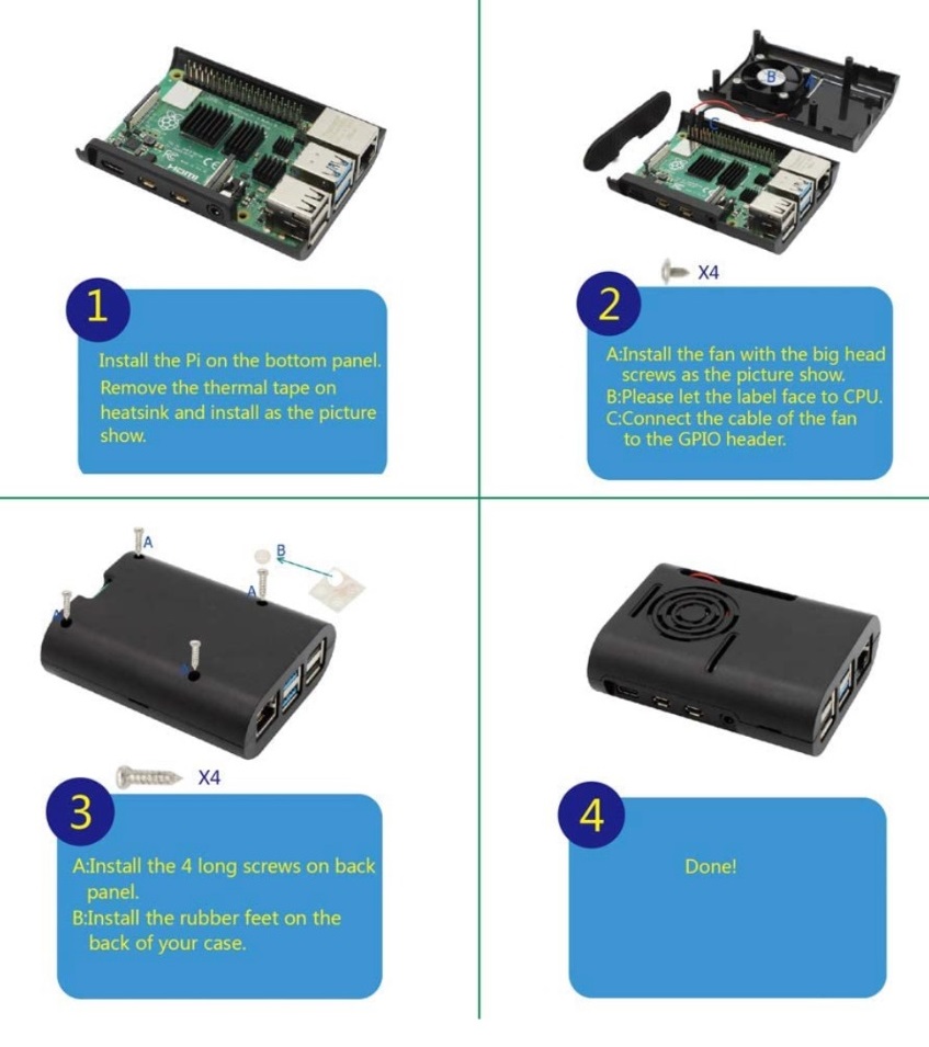
Features
- ABS material.
- Easy to install.
- All ports and slots of the case match with Raspberry Pi 4 Computer Model B perfectly.
- Supports a DC 5v extractor cooling fan.
What's in the box?
1 x ABS Case for Raspberry Pi 4 Model B
1 x Cooling Fan 30mm x 30mm x 7mm
4 x Heat Sinks(new add on to this case)
Resources

Specifications
What's in the box?
1 x CamJam Edukit
Resources
All the worksheets are freely available to download from http://camjam.me/edukit
CamJam Edukit 1 for Raspberry Pi Pico

The CamJam EduKit #2 is the second edition to the EduKit family!
The kit is accompanied by a set of (currently 6) downloadable worksheets (or lesson plans for you educators!) that will take you through a series of exercises and projects, teaching you how to make the most of your kit. Whats best is that there is no soldering required, each high quality component is breadboard friendly!
All the worksheets are freely available to download from http://camjam.me/edukit
What's in the box?
1 x Breadboard
1 x Immersible temperature Sensor
1 x PIR Sensor
1 x LDR
1 x Active Buzzer
1 x Red 10mm LED
1 x Blue 10mm LED
1 x 4.7K Resistor
2 x 330 Resistor
10 x M/F Jumper Wires
4 x M/M Jumper Wires
1 x Presentation Tin
Here are just 4 cool projects you could use the kit for:
- Make a burglar alarm for your bedroom.
- Switch on an LED when it gets dark.
- Have an alarm go off when it’s freezing outside.
- Test whether the light really does go off in the fridge when you shut the door.
Resources
Still not convinced? Check out these awesome articles on the kit!
- "CamJam Edukit 2 Launches at PiWars" - Raspi.tv
- "The CamJam EduKit 2 - Learn How To Use Sensors With The Raspberry Pi" - Average Man vs Raspberry Pi
The CamJam EduKit is a joint venture between The Pi Hut and the Cambridge Raspberry Jam (CamJam). Profits from the sale of the kit will go to CamJam so that they can continue their educational and community work.

All you need to do is to add your own chassis, Raspberry Pi (any model) & batteries! Then, follow the worksheets to make your own motorized buggy. Add the included sensors and you will soon be detecting objects in front of your robot and following line courses.
What's in the box?
A custom-designed, pre-soldered motor controller board (with screw terminals)
2 x DC motors (with wires pre-soldered)
2 x custom red wheels (which go extra fast… because they’re red!)
1 x ball castor (used as the ‘third wheel’ to your robot)
1 x small breadboard (to create your circuits)
2 x pieces of strong 3M padded double-sided tape
1 x battery box for 4 AA batteries (batteries not included)
1 x ultrasonic distance sensor (for detecting objects in front of your robot)
1 x line follower sensor (for detecting and following black lines)
Resistors and jumper cables with which to complete your circuits
A strong cardboard box to keep it all in… or to cut into to make your chassis!
Resources
All the worksheets are freely available to download from http://camjam.me/edukit
Got a 3D printer? Daniel Bull has very kindly designed an awesome chassis, available from Thingiverse ..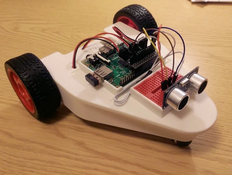
Alex Eames over at Raspi.TV got his hands on a prototype, here's what he did!
https://youtu.be/LJDEV7rGwaM
And here's a fantastic unboxing video from Average Man vs Raspberry Pi!
https://youtu.be/KPYWNXiItwo
And another review! This time from TheRaspberryPiGuy! Thanks Matt!
https://youtu.be/TMjd0UrH2PY

Now with a narrower form factor to fit a wider range of enclosures
Specifications
- Dimensions: 30x30x07mm
- Bearing Type: Sleeve
- Connector: 2PIN
- Rated Voltage: DC 5V, Rated Current: 0.1A
- Airflow: 4.2CFM
- Fan Blade: 7 Blades
- Fan Speed: 5000RPM±10%
- Noise Level: <16dBA±10%
What's in the box?
1 x DC Fan 30x30x7mm

In the first of two volumes, we remake five classic video games – ranging from Pong to Sensible Soccer, each represents a different genre. We interview the games’ original creators and learn from their example, as well as utilise the art and audio engineering skills of two of the 1980s’ most prolific games developers for our recreated versions of the games.
- Get game design tips and tricks from the masters
- Explore the code listings and find out how they work
- Download and play game examples by Eben Upton
- Learn how to code your own games with Pygame Zero
- Read interviews with expert graphics and audio creators

Build CNC routers, 3D printers, CNC laser cutters, CNC plasma cutters, robotics projects, 3D carvers, machine guards, workstations, etc.
Compatible with:
80/20 20 Series, Misumi 5 Series, Openbuilds V-Slot, Openbuilds C-Beam, and other standard v-slot/t-slot 20mm aluminum extrusions
Specifications:
Recommend to use M5 x10mm screw and M5 T nut
Material: Mild Steel
Thickness:3mm
These plates are laser cut from 3mm mild steel and still needs to be painted/powder coated.
What's in the box?
1 x bracket

These kits are perfect for beginners that are just just getting exposed to the Raspberry Pi, Media enthusiasts looking to stream online content with Kodi, developers looking to exploit the many advantages of the RPI's GPIO pins and anybody looking to get some cool goodies at a great price! They contain all of the essential items that you need to get up and running in no time.
Please Note: These kits are pre-boxed and cannot be modified at all, we do however keep stock on all of the individual items so if you have a special need simply feel free to browse through the rest of our product offerings and select the items that you'd like.
What's in the box?
1 x Iconic Raspberry Pi 3 Model A plus
1 x Official 5.1V 2.5A Power Supply in White
1 x black 1m Official HDMI cable
1 x 32 GB Micro SD card with Raspberry Pi OS 64bit pre-loaded
1 x Official Pi3A Red/White Case
Want to take your kit to the next level?
Turn your RPI into a Media Centre
Grab yourself a remote control, install LibreELEC or OSMC when setting up your RPI and you'll be streaming in no time. You can even add a wireless keyboard, mouse or other similar controllers
Want a cheap eco-friendly PC
Grab a Keyboard and Mouse, select Raspbian when setting up your RPI and you'll be browsing the web, sending emails, editing spreadsheets and watching videos just like you're used to with a desktop/laptop.
We know you love retro gaming!
RetroPie allows you to turn your Raspberry Pi into a retro-gaming machine Check out our Arcade section, whether you just want a retro control or a mini DIY arcade cabinet we have what you're looking for.
Did somebody say Robotics?
We've got some cool beginner's items in our robotic section
Our Kits come with the latest version of Raspberry Pi OS pre-installed, While we will certainly try our best to assist with any software related questions we cannot offer any kind of official support on community driven, open source, or non-PiShop produced proprietary software.
NOOBS, Raspbian, RetroPie, LibreELEC and OSMC are all examples of open-source software, please visit the developer's respective websites for more info.
A whole bunch of other really cool technical info can be found here.
Where do I start?.........Getting Started with Raspberry Pi

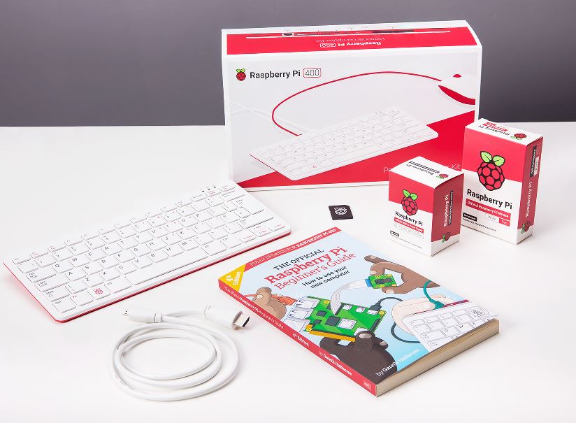
What is in this box?
- The Raspberry Pi 400 with US keyboard
- The Official Raspberry Pi 3A USB type C Power Supply
- The Official Raspberry Pi micro HDMI to HDMI 1m cable
- The Official Raspberry Pi Beginner's Guide
- The Official Raspberry Pi Red/White USB mouse
- Micro SD with Raspberry Pi OS pre-installed
Overview
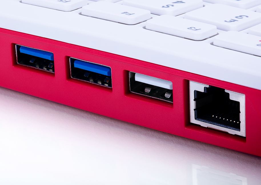
Featuring a quad-core 64-bit processor, wireless networking, dual-display output and 4K video playback, Raspberry Pi 400 is a complete personal computer, built into a compact keyboard.
Raspberry Pi 400 is ideal for surfing the web, creating and editing documents, watching videos, and learning to program using the Raspberry Pi OS desktop environment.
Raspberry Pi 400 computer kit contains everything you need to get started (except for a TV or monitor).
Raspberry Pi 400 for working and learning at home
Specifications
Processor: Broadcom BCM2711 quad-core Cortex-A72 (ARM v8) 64-bit SoC @ 1.8GHz
RAM: 4GB LPDDR4-3200
Connectivity: Dual-band (2.4GHz and 5.0GHz) IEEE 802.11b/g/n/ac wireless LAN, Bluetooth 5.0, BLE Gigabit Ethernet
2 × USB 3.0 and 1 × USB 2.0 ports
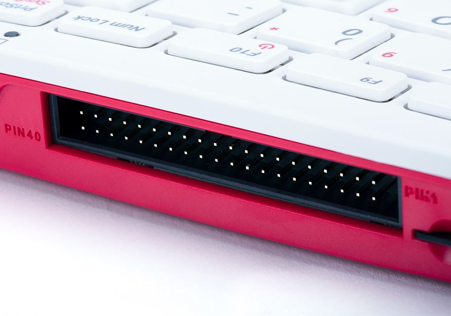
GPIO Horizontal 40-pin GPIO header
Video & sound: 2 × micro HDMI ports (supports up to 4Kp60)
Multimedia: H.265 (4Kp60 decode);
H.264 (1080p60 decode, 1080p30 encode);
OpenGL ES 3.0 graphics
SD card support: MicroSD card slot for operating system and data storage
Keyboard: 78- or 79-key compact keyboard (depending on
regional variant)
Power: 5V DC via USB type C connector
Operating temperature: 0°C to 50°C
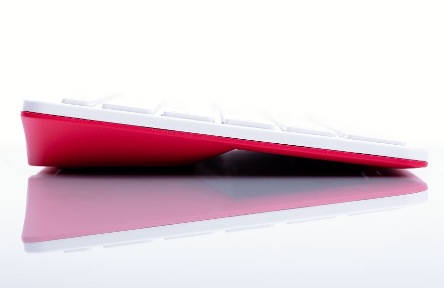
Dimensions: 286 mm × 122 mm × 23 mm (maximum)
Compliance: For a full list of local and regional product approvals, please visit
www.raspberrypi.org/documentation/hardware/raspberrypi/conformity.md
WARNINGS
• Any external power supply used with Raspberry Pi 400 shall comply with relevant regulations and
standards applicable in the country of intended use.
• This product should be operated in a well-ventilated environment and should not be covered when
being operated.
• The connection of incompatible devices to Raspberry Pi 400 may affect compliance, result in damage to the unit, and invalidate the warranty.
• There are no user-serviceable parts inside Raspberry Pi 400, and opening the unit is likely to damage the product and will invalidate the warranty.
• All peripherals used with this product should comply with relevant standards for the country of use
and be marked accordingly to ensure that safety and performance requirements are met. These
articles include, but are not limited to, mice, monitors and cables when used in conjunction with
Raspberry Pi 400.
• The cables and connectors of all peripherals used with this product must have adequate insulation so that relevant safety requirements are met.
• Prolonged exposure to direct sunlight may cause discoloration.
SAFETY INSTRUCTIONS
To avoid malfunction or damage to this product please observe the following:
• Do not expose to water or moisture whilst in operation.
• Do not expose to heat from any source; Raspberry Pi 400 is designed for reliable operation at normal ambient temperatures.
• Take care whilst handling to avoid mechanical or electrical damage to the computer.
Accreditation


This Starter Kit is based around the Arduino Compatible Uno development board which features the AVR ATmega328 microcontroller. The kit includes a getting started book to guide you throught the process of using your Arduino for the first time. Starting the basics of electronics, to more complex projects, the kit will help you control the physical world around you.
What's in the box?
- UNO R3 MEGA328P ATMEGA16U2 Arduino Compatible board including USB cable
- 9V 1A AC to DC Power Supply for Arduino
- Mini Breadboard - White
- 120Pcs 10cm Breadboard Jumper Cable Kit
- The GET STARTED WITH ARDUINO book.
Who is it designed for?
The Arduino Uno Starter Kit is suitable for almost all ages. It is designed for those who are new to Arduino and electronics, and is designed to introduce you to the world of code, circuits and breadboards.However, even if you’re an experienced designer, the Arduino Starter Kit is a great way to tinker about with the different functionalities of the Arduino Uno.
The Arduino Community
The Get Started with Arduino Book is there to help but there is also a huge community surrounding Arduino. So, if you are ever stuck or require some guidance with your projects, the Arduino site is full of content to keep you going. Or, if you find you are stuck for ideas to tinker about with, there’s plenty of projects on the site to give you some inspiration
The Get Started with Arduino book features the following projects to get you started:
- Reading digital data on the Arduino
Hardware: Monumentary push-button, 1 x 10k ohm resistor - Seven-segment Displays and multidimentional arrays
Hardware: single-digit 7 segment display, 7 x 220 ohm resistors - Multiplexing, operators and four seven-segments
Hardware: 1 x 4 digit 7 segment display, 7 x 330 ohm resistors - Temperature, humidity and libraries
Hardware: , 4 digit 7 segment display, 7 x 330 ohm resistors - Stacks, classes and scrolling displays
Hardware: DHT11, SSD1306 OLED - Pointers and linked lists
Hardware: DHT11, SSD1306 OLED - Building a games console
Hardware: Joystick, SSD1306 OLED - Sound, envelopes and interrupts
Hardware: Speaker, Monumentary push-button, 10 k resistor, Buzzer - Copy and send infrared signals
Hardware: Monumentary push-button, 10k resistor, IR reciever diode IR transmitter photodiode
We do also stock enclosures for the Arduino

MicroPython is a full implementation of the Python 3 programming language that runs directly on embedded hardware like Raspberry Pi Pico. You get an interactive prompt (the REPL) to execute commands immediately via USB Serial, and a built-in filesystem. The Pico port of MicroPython includes modules for accessing low-level chip-specific hardware.
What is Raspberry Pi Pico?
Raspberry Pi Pico, a microcontroller board built on silicon designed here at Raspberry Pi.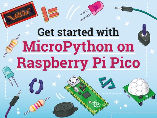
Your official guide
Microcontrollers, like RP2040 at the heart of Raspberry PiPico, are computers stripped back to their bare essentials. You don’t use monitors or keyboards, but program them to take their input from, and send their output to the input/output pins. Using these programmable connections, you can light lights, make noises, send text to screens, and much more. In Get Started with MicroPython on Raspberry Pi Pico, you will learn how to use the beginner-friendly language MicroPython to write programs and connect up hardware to make your Raspberry Pi Pico interact with the world around it. Using these skills, you can create your own electro‑mechanical projects, whether for fun or to make your life easier.
Contents of the Raspberry Pi Pico book:
Chapter 1: Get to know your Raspberry Pi Pico
Get fully acquainted with your powerful new microcontroller and learn how to attach pin headers and install MicroPython to program it
Chapter 2: Programming with MicroPython
Connect a computer and start writing programs for your Raspberry Pi Pico using the MicroPython language
Chapter 3: Physical computing
Learn about your Raspberry Pi Pico’s pins and the electronic components you can connect and control
Chapter 4: Physical computing with Raspberry Pi Pico
Start connecting basic electronic components to your Raspberry Pi Pico and writing programs to control and sense them
Chapter 5: Traffic light controller
Create your own mini pedestrian crossing system using multiple LEDs and a push-button
Chapter 6: Reaction game
Build a simple reaction timing game using an LED and push-buttons, for one or two players
Chapter 7: Burglar alarm
Use a motion sensor to detect intruders and sound the alarm with a flashing light and siren
Chapter 8: Temperature gauge
Use your Raspberry Pi Pico’s built-in ADC to convert analogue inputs, and read its internal temperature sensor
Chapter 9: Data logger
Turn Raspberry Pi Pico into a temperature data-logging device and untether it from the computer to make it fully portable
Chapter 10: Digital communication protocols: I2C and SPI
Explore these two popular communication protocols and use them to display data on an LCD
What's in the box?
1 x Pico MicroPython book

This LCD accepts 8-bits/9-bits/16-bits/18-bits parallel interface, that are RGB444, RGB565, RGB666. The color format used in demo codes is RGB565.
This LCD uses a 4-line SPI interface for reducing GPIO and fast speed.LCD
Features at a glance
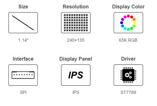
- 240×135 resolution, IPS screen, 65K RGB colors, clear and colorful displaying effect
- SPI interface, requires minimal IO pins
- 1x joystick and 2x user buttons for easy interacting
- Comes with development resources and manual (Raspberry Pi Pico C/C and MicroPython examples)
Specifications
| Operating voltage | 2.6 ~ 5.5V | Resolution | 240×135 pixels |
|---|---|---|---|
| Communication Interface | 4-wire SPI | Display size | 24.91 × 14.86mm |
| Display Panel | IPS | Pixel size | 0.1101 × 0.1035mm |
| Driver | ST7789 | Dimensions | 52.00 × 25.00mm |
Raspberry Pi Pico header compatibility
- Onboard female pin header for direct attaching to Raspberry Pi Pico
- 1x joystick and 2x user buttons for easy interacting
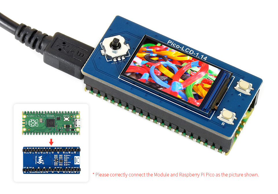
Raspberry Pi Pico is NOT included.
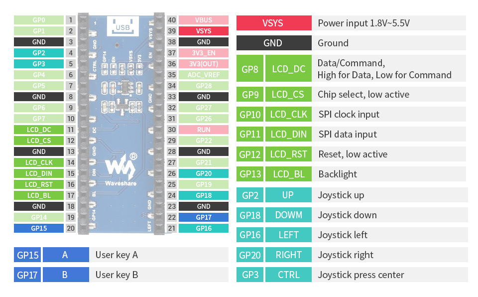
Pinout definition
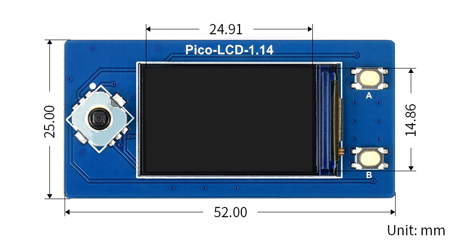
Outline dimensions
What's in the box?
1 x 1.14inch LCD Display Module for Raspberry Pi Pico
Resources

Features
- Mecer Optical Wheel Mouse : USB
- Ergonomic design
- Light
What's in the box?
1 x USB optical Mouse


- High performance intelligent multi-frequency scanning use active matrix Thin film transistor liquid crystal display (TFT), LED backlight
- Comply with VESA DPMS International Power Saving Regulation
- Support DDC 1/2B and Windows PNP Plug & Play
- Microprocessor based with OSD (On Screen Display) control, able to adjust the image to optimum
- Complying with International Standard (VESA) to mount the display on the wall
- 19.5" (49.53cm) 16:9 wide LED
- Resolution 1600x900@60Hz
- Brightness 250cd/m²
- Viewing Angle 90°/65°(H/V)
- Net weight 2.14kgs
- Gross weight 3kgs
- Ultra slim
What's in the box?
1x LED monitor (with pedestal)
1x VGA signal cable
1x Audio cable
1x Power cord cable
1x User manual

There are a lot of people, even experienced computer users, who use a mouse without a mouse pad, but if you care about your mouse (and whatever's underneath it), you should put a pad between them.
Mecer mouse pad for optical mouse