
ModMyPi


MODULAR CASE NOT INCLUDED
The Modular Raspberry Pi Case is designed to be fully customisable by the user, and adaptable to suit a range of requirements. The streamlined look, and adaptability makes it perfect for many applications, including: the hobbyist maker, digital signage, industrial protection, living-room & child-friendly media centres, classroom eduction, workshops and many more! All add-ons are designed to be interchangeable and can be added and removed when required.
The USB/HDMI security cover is a dual-use shroud that can be utilised to protect access to all the external inputs and outputs. Two covers can be used simultaneously if only very limited access is required, and “punch-out” access hatches are available for both the Ethernet and Micro USB power port if these inputs are required. Security covers are tamperproof and can only be removed from inside the case.
In addition to protecting the Raspberry Pi ports, the shroud is offset from the body by 12mm. The enables the secure, internal and protected use of up to four nano USB dongles with the cover installed.
Specifications:- Dual-Use - Compatible with Either Set of I/O Ports e.g. HDMI or USB Side
- Secure and Tamper-Proof
- RJ45 & Micro USB Power Breakout Hatches
- Off-Set to Enable the Use & Internal Protection of up to 4 Nano USB Dongles!
- 1 x USB/HDMI Cover

RASPBERRY PI NOT INCLUDED(Neither the key-ring and keys for those who wondered)
This cute little GPIO reference board from allows you to quickly and easily distinguish between the different pins of the Raspberry Pi Model B , Raspberry Pi 2B, Pi 3B and Pi 4B . It's even got a key chain hole, so you can carry it around and keep it handy - you'll never know when you need to hack a Pi!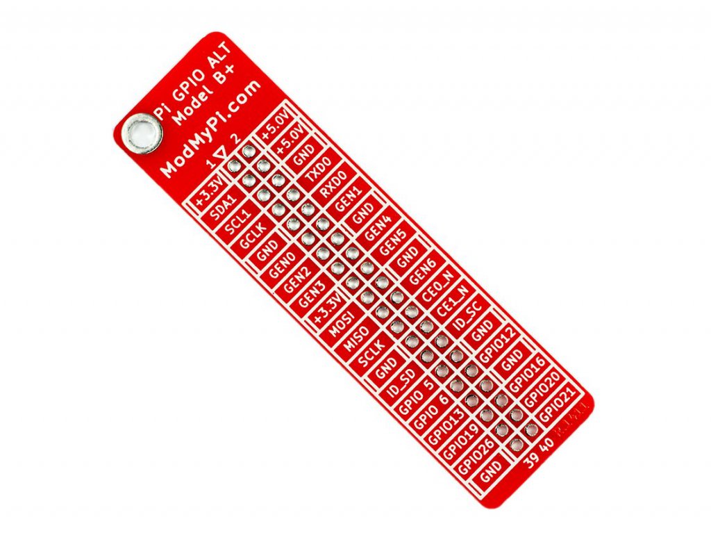
The GPIO reference board features BCM numbering on one side and the pin names on the other. It can be soldered for permanent referencing, or slipped on and off when required.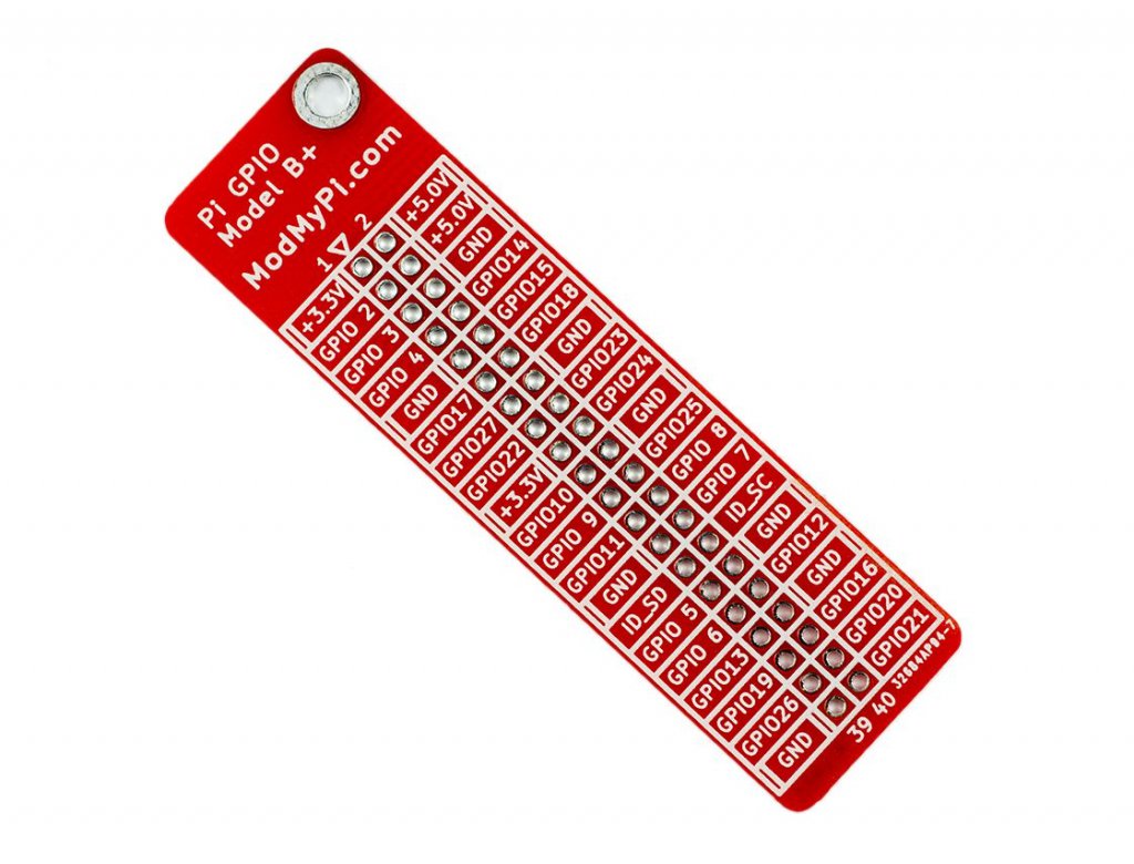
On the RPi3 and later you'll have to snip off a little bit of the corner closest to pin 39 thanks to the new POE pins on the board
What's in the box?
1 x GPIO reference board

RASPBERRY PI BOARD NOT INCLUDED
Description:
Whether you're pulling-up or pulling-down, there's no need to frown! With the PUD board from ModMyPi, adding multiple pull-up or pull-down resistors to your Raspberry Pi project is easy!
If you want to detect an "output" with your Raspberry Pi, like a button being pressed or a motion sensor detecting movement, we can configure our Raspberry Pi's GPIO pin as an "input". That input pin can be in three states (known as Tri-State logic); "high", when 3.3V is applied, "low", when the pin is connected to 0V, and "floating" when the state is undefined. Floating voltages are troublesome in electronics as the input can either read high or low depending on various fluctuations in electrical noise. Like a gate flapping open and closed in the wind, someone needs to lock the gate closed, or wedge it open. If you leave it flapping, it's likely to hit someone on their bottom on the way through!
Like our gate, the best way to avoid a floating input is to "tie" your input pin either high or low to create a default state. This is usually achieved through the use of a pull-up or pull-down resistor, either connecting our input pin via a resistor to the Pi's 3.3V to achieve a 3.3V high state, or the GND line to achieve 0V low state.
Our PUD board takes the messy wiring out of adding a pull-up or pull-down resistor to your circuit. Simply wire up the sensor output to the single pin on the PUD board and add a shunt jumper to either pull up (u) or down (d)! Therefore when you apply a signal voltage from your sensor or switch, the Pi is easily able to sense into which logic state the pin has been pulled! No more trouble from floating I/O's!
The PUD boards connects across GPIO pins 11 to 18 (17 to 24 in BCM speak), and adds a jumper configurable pull-up or pull-down resistor to each GPIO pin: 11 (BCM 17), 12 (BCM 18), 13 (BCM 27), 15 (BCM 22), 16 (BCM 23) and 18 (BCM 24). Pin 17 (3.3V) & pin 14 (GND) are used to tie the pins!
The PUD Board Features:
- Add a pull-up or pull-down resistor to your GPIO with the swap of a jumper!
- Compatible with all Raspberry Pi Models Inc. A /B /2/3 & Zero/ZeroW
- Tiny board means it's easy to integrate into any circuit - takes up just 8 GPIO pins
- Connects across GPIO pins 11 to 18 inclusive (BCM 17 to 24)
- In-line 1kΩ current limiting resistors on each GPIO
- 10kΩ pull-up or pull-down resistors on each GPIO
- All 6 GPIO pins can be configured independently
- Includes 6 x 2 Pin Shunt Jumpers & 1 x PUD Board
- Jumper configurable pull-up or pull-down resistor on pins:
- 11 (BCM 17)
- 12 (BCM 18)
- 13 (BCM 27)
- 15 (BCM 22)
- 16 (BCM 23)
- 18 (BCM 24).
- Pin 17 (3.3V) & Pin 14 (GND) are used to tie the pins!
- To pull pin up, connect the jumper across "u" and the center pin
- To pull pin down, connect the jumper across "d" and the center pin
What's in the box:
1 x PUD Board
Tutorials:
The back for the cover for SmartiPi Touch 2 allows you to cover HAT boards or other additional electronics on the back of the SmartiPi Touch 2.
The covers include four M4 mounting screws that attach the cover to the 75mm VESA mount holes on the back of the case.
Note: The cover does not work with the door or the fan door.
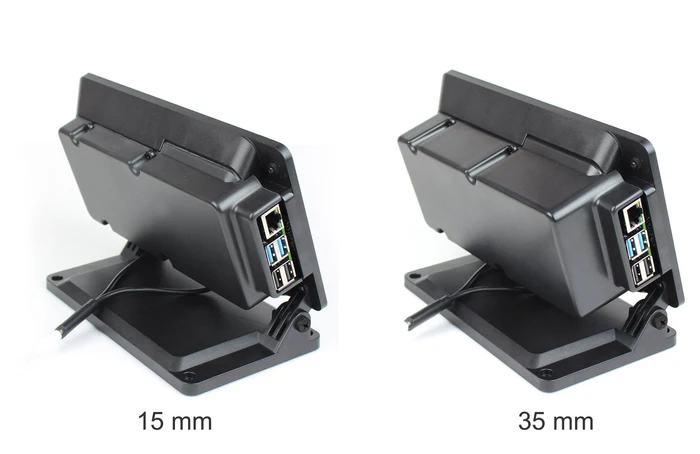
Choose between 35mm and 15mm versions. Dimensions are inside dimensions from the back of SmartiPi Touch. They are made out of ABS plastic.
What's in the box?
1 x Smartipi Touch 2 backcover
The back for the cover for SmartiPi Touch 2 allows you to cover HAT boards or other additional electronics on the back of the SmartiPi Touch 2.
The covers include four M4 mounting screws that attach the cover to the 75mm VESA mount holes on the back of the case.
Note: The cover does not work with the door or the fan door.
Choose between 35mm and 15mm versions. Dimensions are inside dimensions from the back of SmartiPi Touch. They are made out of ABS plastic.
What's in the box?
1 x Smartipi Touch 2 backcover
- 1