
Special Offers


Compatible with: 80/20 20 Series, Misumi 5 Series, Openbuilds V-Slot, Openbuilds C-Beam, and other standard v-slot/t-slot 20mm aluminum extrusions
Specifications
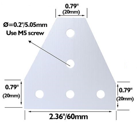
- For the 2020 the size is 60mm x 60mm x 4mm, recommend to use M5 x10mm screw and M5 T nut
- Material: Aluminium
- Colour: Silver
- Aperture:M5
- Holes Spaced:20mm / 0.79 inch
- Thickness:4mm / 0.16 inch
- Dimensions: 60mm x 60mm /2.36 x 2.36 inch
What's in the box?
1 x bracket

It can easily cut all kinds of soft material below 1.2mm thickness. Wire under 0.8MM.
Suitable for cutting wires, electronic feet, trimming plastic parts etc.
What's in the box?
1 x electronic parts cutting pliers

Specifications
- Light, small and easy to use
- Double - quick screw down.
- Saved time and manpower for installation.
- Size: 108mm x 30mm x41mm/4.25 x 1.18 x 1.61inch
What's in the box?
2 x MC4 spanners
This tiny but powerful 30mm fan can be used in any electronic projects, with MCUs, and even to keep your Raspberry Pi cool.
Now with a narrower form factor to fit a wider range of enclosures
Specifications
- Dimensions: 30x30x07mm
- Bearing Type: Sleeve
- Connector: 2PIN
- Rated Voltage: DC 5V, Rated Current: 0.1A
- Airflow: 4.2CFM
- Fan Blade: 7 Blades
- Fan Speed: 5000RPM±10%
- Noise Level: <16dBA±10%
What's in the box?
1 x DC Fan 30x30x7mm
4 x M2.5 x 14 screws
4 x M2.5 nuts
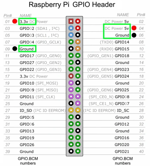
Resources
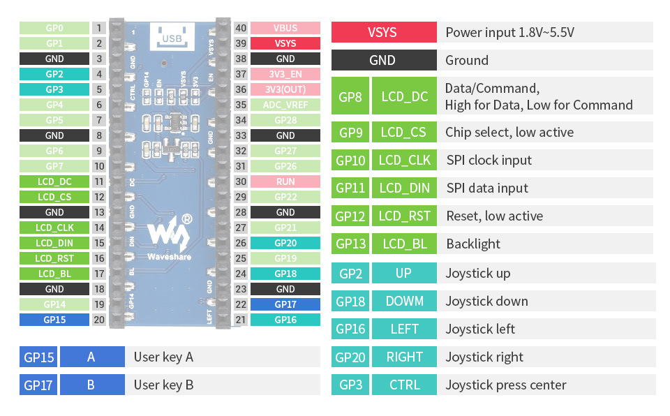
3.3V connection to the GPIO on the left and 5V on the right.

Ever fancied creating your own first-person shooter game? Now you can with this 140-page bookazine, brought to you by the Wireframe magazine team with tips from expert video game developers!
Making a fast-paced 3D action game needn’t be as daunting as it sounds. Build Your Own First-Person Shooter in Unity will take you step-by-step through the process of making Zombie Panic: a frenetic battle for survival inside a castle heaving with the undead.
Specifications:
- Set up and use the free software you’ll need
- Make enemies that follow and attack the player
- Create and texture 3D character models
- Extend your game further, with tips from experts
- Design a level with locked doors and keys
What's in the box?:
1 x 140-page bookazine
Resources:

Build CNC routers, 3D printers, CNC laser cutters, CNC plasma cutters, robotics projects, 3D carvers, machine guards, workstations, etc.
Compatible with:
80/20 20 Series, Misumi 5 Series, Openbuilds V-Slot, Openbuilds C-Beam, and other standard v-slot/t-slot 20mm aluminum extrusions
Specifications:
Recommend to use M5 x10mm screw and M5 T nut
Material: Mild Steel
Thickness:3mm
These plates are laser cut from 3mm mild steel and still needs to be painted/powder coated.
What's in the box?
1 x bracket
Red T-shirt White Logo Adult Size. Sizing is to a standard UK high-street size, and the shirts fit true to size. We recommend purchasing your usual size. If you fall between two sizes, we advise purchasing the larger size. (Size guide available in product images)
Specifications:
Certified organic cotton 155g/m2
GM free
Not tested on animals
Does not contain animal-derived products
Printed in the UK with low-waste printing tech
Maintaining your tee: wash cool and hang dry to ensure print quality and longevity.

This is a practical, yet elegant Raspberry Pi Ceramic mug from the Raspberry Pi Foundation. Let your Raspberry Pi spirit shines :) Be the envy of everyone in your office with the new Raspberry Pi mug!

- Red color with White Raspberry Pi Logo
- Dishwasher safe
- 80mm diameter x 90mm tall
- 330ml capacity
- Bright and colorful!
The team at Raspberry Pi Foundation has extensively tested these mugs and can confirm that they are tea-, coffee-, and hot chocolate-compatible. They can also be used for cold drinks if that's your preference.
Note: While tested to over 1,000 domestic dishwasher cycles, it is recommended that you hand-wash this mug to keep it in tip-top condition.
Packing List:- 1 x Raspberry Pi Red Ceramic Mug

The DINrPlate 2 (DRP2) is a simple, reliable and cost-effective DIN Rail Mount solution for the Raspberry Pi 5/4/3/2/B .
The plate has easy access for all ports and GPIO pins and features a vertical design using just 32mm of DIN space - held with large secure 10mm DIN clips which will not release without the use of a screwdriver.
Integrated strain relief for the power cable has been included in the design (tie wrap included) and the entire plate is made from high-quality 6/6 Nylon (well suited for industrial environments). The SD card is easily accessible for maintenance.
The plate comes in an industrial grey colour to blend in well with other panel components for a professional finish.
Specifications
- DIN clips size: 10mm
- Material: 6.6 Nylon
- Dimensions: 3.6" x 0.4" x 3.6"
- Weight: 0.8 oz
- Colour: Industrial grey
What's in the box?
1 x DINrPlate 2
4 x mounting screws
1 x tie wrap
Resources
- Attach Raspberry Pi board to the base using included four (4) M2 screws and a small Phillips screwdriver (not included).
- Insert the power cable into the Raspberry Pi. Note: Some speciality USB power cables may have a clearance issue with integrated strain relief. If this is the case, use a standard USB power cable.
- Secure power cable in place with included tie-wrap, and cut off any excess tie wrap.
- Attach the base to 35mm DIN rail using a medium-size flat head screwdriver (not included), using a lever action on the flexible side of the DIN rail clip until there is enough clearance to completely grip the DIN rail edges. Use caution when using screwdriver to not bend clip more than is necessary to be attached.

The ultimate desktop retro arcade machine! Picade is a Raspberry Pi-powered mini arcade that you build yourself, with authentic arcade controls, a high resolution 4:3 display that's ideal for retro gaming, and a punchy speaker to hear those 8-bit game soundtracks at their best
Picade is now Raspberry Pi 4 compatible and includes a new USB-C version of Picade X HAT!
The all-new Picade has been completely redesigned, from the inside out! There's new artwork, a new display and display driver board, dedicated power button, an all-new Picade X HAT (now with USB-C), easier wiring, easier access to the interior of the cabinet, beautiful new packaging, a bunch of extra goodies (stickers and an enamel Picade pin), and a gorgeous Picade poster and assembly instructions.
Picade comes in kit form, and it'll take around two to three hours to build. The cabinet is made from powder-coated MDF, giving it a quality look and feel similar to a full-size arcade. All you'll need to add is a Raspberry Pi, USB-C power supply, and micro-SD card.
Cabinet features
- Black, powder-coated panels
- Acrylic marquee and console with authentic artwork
- Push-fit arcade buttons
- Joystick with black ball top
- 3" speaker (5W, 4Ω)
- Easy access with removable back panel
- Dedicated illuminated power button
- Grippy rubber feet
- Dimensions: 350x230x210mm
10-inch display features
- 1024x768 (4:3 ratio) IPS (wide viewing angle) display
- Pimoroni-designed and manufactured HDMI display driver board and keypad controls
- Powered by micro-USB cable (included) from your Pi
Picade X HAT features
- Easy DuPont connectors for buttons and joystick
- Push-fit speaker terminals
- I2S audio DAC with 3W amplifier (mono)
- Power management, power switch pins, and power button
- 4-way joystick inputs
- 6 player buttons
- 4 utility buttons
- Metal standoffs to hold your Picade X HAT securely
Extras
- Picade enamel pin badge
- Pimoroni Super Sticker Selection
- Picade poster / assembly instructions
What's new!?
The cabinet is more compact, so it fits more neatly on your desk, but has a higher resolution 8" or 10" display (1024x768). The display is driven by a new Pimoroni-designed and manufactured driver board, with keypad controls. It's an IPS panel, so it looks great from any viewing angle!
The all-new Picade X HAT is packed full of useful features. We've moved from more fiddly screw terminals to simple DuPont connectors that just push in, and the speaker terminals are the same easy push-fit connectors that we use on pHAT BEAT.
There's dedicated power management on-board Picade X HAT; just plug your micro-USB power supply into the HAT and it'll power your Pi through its pins. The power button connected to the HAT means that once your Pi is safely shutdown, the power will be cut completely to the Pi. A simple press of the power button will boot your Picade up again.
The new buttons in Picade are lower profile, and the new joystick has a single connector rather than the eight spade connectors on our previous Picade joystick.
A gorgeous new neon-look Picade logo on the marquee, and rainbow stripes on the console and screen-surround, evoke classic consoles, as do the assembly instructions and poster.
Building your Picade
We hope the included assembly instructions have everything you need to build your Picade, but we've also filmed a complete build video of Picade that you can watch as you build and learn some handy tips and tricks. Find it at https://youtu.be/gTgu1fUVsmw
The sections are also available separately in a playlist here.
We've also put together an online tutorial that incorporates the assembly instructions, important tips and amendments, and the videos for each section, so do check that out!
Software setup
We recommend the RetroPie operating system for your Picade. You can download it from the RetroPie website and then burn it to a micro-SD card with Etcher.
Connect a USB keyboard to your Pi, and connect to Wi-Fi in the RetroPie menu. Press F4 to exit to the terminal and then type curl https://get.pimoroni.com/picadehat | bash to run the Picade HAT installer.
Reboot your Pi, if it doesn't prompt you to. Press the "Alt" key on your keyboard and then select "Configure input" to configure your Picade's controls. You'll find that the sound and power button should both be working now too!
Notes
If your Picade display doesn't show anything when you first power it up, then it could be because the HDMI display is not being detected by the Raspberry Pi. This can happen because power isn't supplied to the USB ports on the Raspberry Pi for the first few seconds of booting. The solution is to edit the /boot/config.txt file on your RetroPie SD card, and add hdmi_force_hotplug=1 on a new line at the bottom of the file.
If you'd like to design your own artwork for your Picade, then we've made a handy PDF that has the outlines and dimensions of the marquee, screen shim, and console. You can download it from the Picade HAT GitHub repo here.
Where to find ROMs for RetroPie (free and legally) https://howchoo.com/g/otiwyjhlnzb/where-to-find-roms-for-retropie
and here http://cvaddict.com/article.php?articleid=15
Please Note: These kits are pre-boxed and cannot be modified at all, we do however keep stock on all of the individual items so if you have a special need simply feel free to browse through the rest of our product offerings and select the items that you'd like.
What's in the box?
1 x Iconic Raspberry Pi 3 Model A plus
1 x Official 5.1V 2.5A Power Supply in White
1 x black 1m Official HDMI cable
1 x 32 GB Micro SD card with Raspberry Pi OS 64bit pre-loaded
1 x Official Pi3A Red/White Case
Want to take your kit to the next level?
Turn your RPI into a Media Centre
Grab yourself a remote control, install LibreELEC or OSMC when setting up your RPI and you'll be streaming in no time. You can even add a wireless keyboard, mouse or other similar controllers
Want a cheap eco-friendly PC
Grab a Keyboard and Mouse, select Raspbian when setting up your RPI and you'll be browsing the web, sending emails, editing spreadsheets and watching videos just like you're used to with a desktop/laptop.
We know you love retro gaming!
RetroPie allows you to turn your Raspberry Pi into a retro-gaming machine Check out our Arcade section, whether you just want a retro control or a mini DIY arcade cabinet we have what you're looking for.
Did somebody say Robotics?
We've got some cool beginner's items in our robotic section
Our Kits come with the latest version of Raspberry Pi OS pre-installed, While we will certainly try our best to assist with any software related questions we cannot offer any kind of official support on community driven, open source, or non-PiShop produced proprietary software.
NOOBS, Raspbian, RetroPie, LibreELEC and OSMC are all examples of open-source software, please visit the developer's respective websites for more info.
A whole bunch of other really cool technical info can be found here.
Where do I start?.........Getting Started with Raspberry Pi
Raspberry Pi 400 is a complete Raspberry Pi 4-based personal computer, fully integrated into a keyboard for ease of setup and use.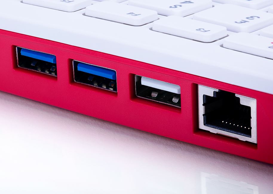
Overview
Featuring a quad-core 64-bit processor, wireless networking, dual-display output and 4K video playback, Raspberry Pi 400 is a complete personal computer, built into a compact keyboard.
Raspberry Pi 400 is ideal for surfing the web, creating and editing documents, watching videos, and learning to program using the Raspberry Pi OS desktop environment.
Raspberry Pi 400 is available in a number of different regional variants and as either a computer kit, containing everything you need to get started (except for a TV or monitor), or a computer unit only.
Raspberry Pi 400 for working and learning at home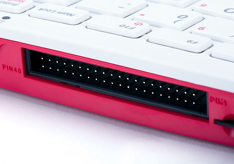
Specifications
Processor: Broadcom BCM2711 quad-core Cortex-A72 (ARM v8) 64-bit SoC @ 1.8GHz
RAM: 4GB LPDDR4-3200
Connectivity: Dual-band (2.4GHz and 5.0GHz) IEEE 802.11b/g/n/ac wireless LAN, Bluetooth 5.0, BLE Gigabit Ethernet
2 × USB 3.0 and 1 × USB 2.0 ports
GPIO Horizontal 40-pin GPIO header
Video & sound: 2 × micro HDMI ports (supports up to 4Kp60)
Multimedia: H.265 (4Kp60 decode);
H.264 (1080p60 decode, 1080p30 encode);
OpenGL ES 3.0 graphics
SD card support: MicroSD card slot for operating system and data storage
Keyboard: 78- or 79-key compact keyboard (depending on
regional variant)
Power: 5V DC via USB connector
Operating temperature: 0°C to 50°C
Dimensions: 286 mm × 122 mm × 23 mm (maximum)
What's in the box?
1 x Raspberry Pi400 unit only(US keyboard)
1 x Raspberry Pi 32GB preloaded with RPi OS micro SD card(Included from 09/12/2024)
You might also need .....
- a display monitor in red/white or black
- a USB type C power supply available in white or black
- a micro HDMI cable or HDMI adapter
- a mouse in red or black
Compliance: For a full list of local and regional product approvals, please visit
www.raspberrypi.org/documentation/hardware/raspberrypi/conformity.md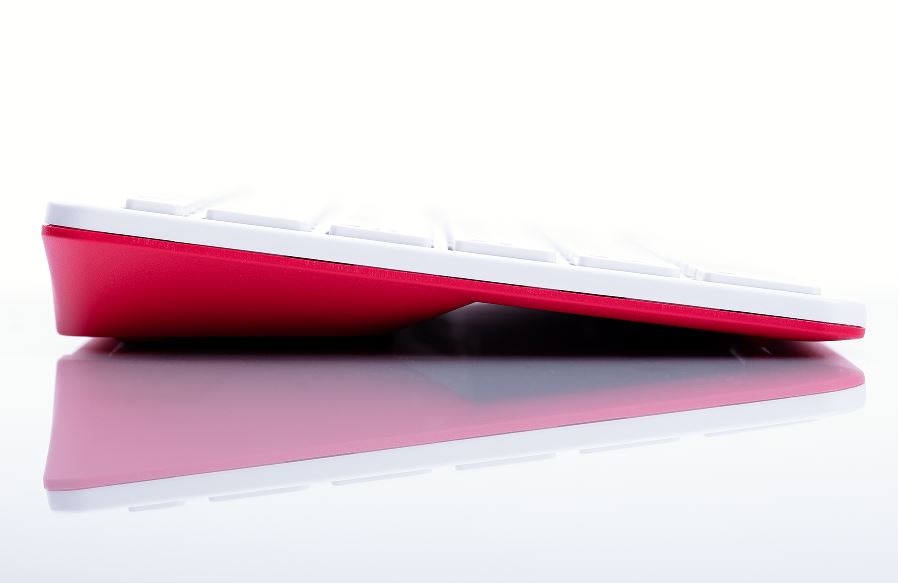
WARNINGS
• Any external power supply used with Raspberry Pi 400 shall comply with relevant regulations and
standards applicable in the country of intended use.
• This product should be operated in a well-ventilated environment and should not be covered when
being operated.
• The connection of incompatible devices to Raspberry Pi 400 may affect compliance, result in damage to the unit, and invalidate the warranty.
• There are no user-serviceable parts inside Raspberry Pi 400, and opening the unit is likely to damage the product and will invalidate the warranty.
• All peripherals used with this product should comply with relevant standards for the country of use
and be marked accordingly to ensure that safety and performance requirements are met. These
articles include, but are not limited to, mice, monitors and cables when used in conjunction with
Raspberry Pi 400.
• The cables and connectors of all peripherals used with this product must have adequate insulation so that relevant safety requirements are met.
• Prolonged exposure to direct sunlight may cause discoloration.
SAFETY INSTRUCTIONS
To avoid malfunction or damage to this product please observe the following:
• Do not expose to water or moisture whilst in operation.
• Do not expose to heat from any source; Raspberry Pi 400 is designed for reliable operation at normal ambient temperatures.
• Take care whilst handling to avoid mechanical or electrical damage to the computer.
Accreditation

The four LEDs on the breakout board are there to illuminate the subject with an even light source, making measurement more reliable.
You can use the TCS230 where you need to take action based on the color of an object. The device does react to infrared so may need an infrared filter or use the device in an enclosed space.
Features
- Chip: TCS230
- Input voltage: DC 3V-5V
- Output frequency voltage: 0 ~ 5V
- Use bright white LED lights
- Can be connected directly with Microcontroller
- Static detection of the measured object color
- Best detection distance: 10mm
What's in the box?
1 x colour recognition sensor

- POE: integrates 802.3af-compliant PoE circuit (5V/2.5A)
- USB: 4x USB 3.2 Gen1 portsMicro USB port
- Ethernet: Gigabit Ethernet RJ45 with PoE support
- Header: Color-coded 40PIN GPIO header
- Fan: 5V / 12V standard fan connector
- Power Input: 7V~36V
- CM4 Socket: suitable for all variants of Compute Module 4
- RTC: Real-time clock with battery socket and ability to wake Compute Module 4
- Video: 2x MIPI DSI display FPC connectors (22-pin 0.5 mm pitch cable)
- Camera: 2x MIPI CSI-2 camera FPC connectors (22-pin 0.5 mm pitch cable)
- SD card slot: MicroSD card socket for Compute Module 4 Lite (without eMMC) variants
- Dimensions: 160 × 90mm
Standard CM4 socket and color-coded Raspberry Pi 40PIN GPIO header suitable for all variants of Compute Module 4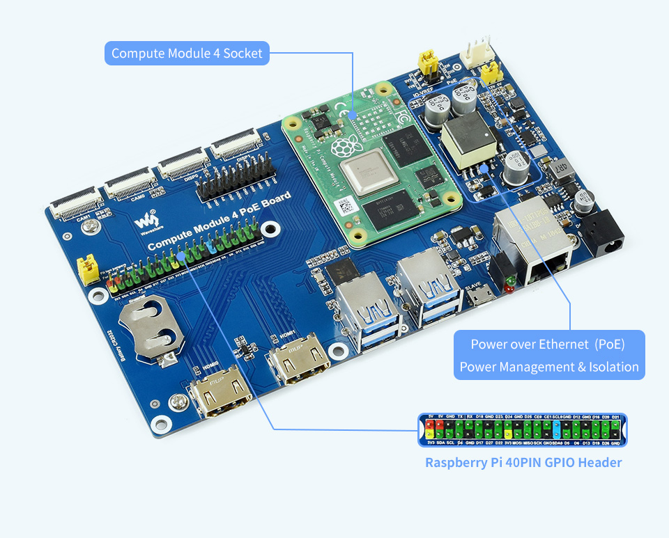
Onboard connectors including CSI/DSI/RTC/HDMI/USB/ETH/TF card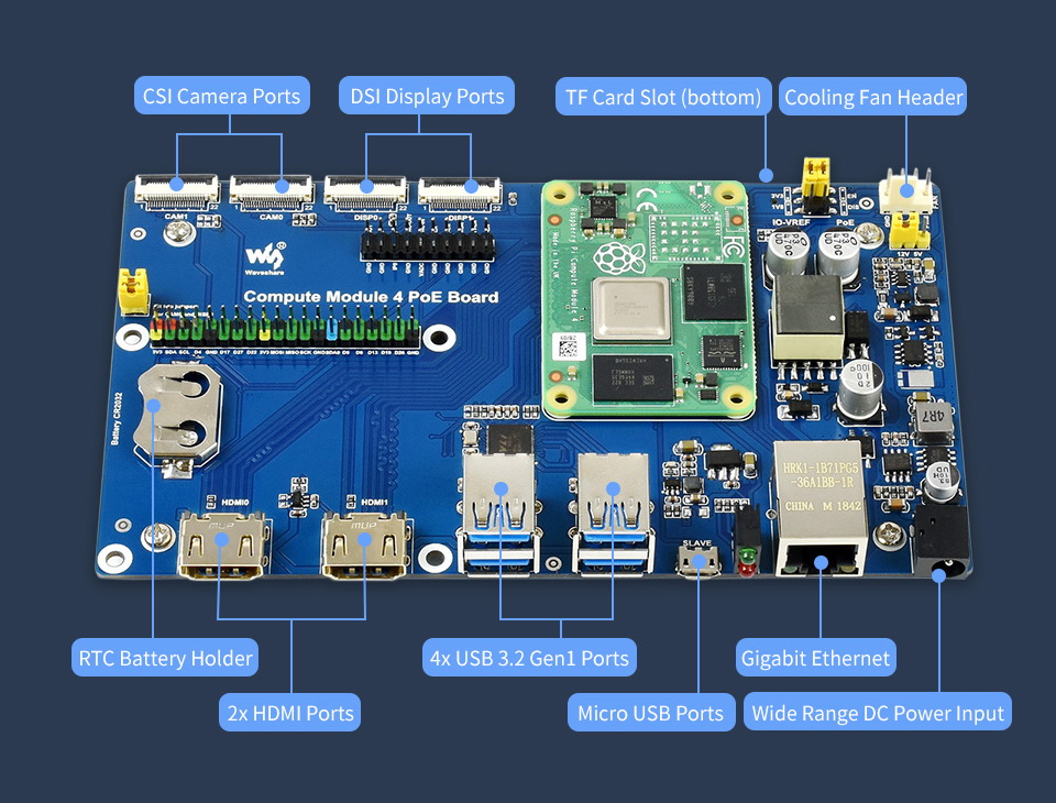
What's On Board?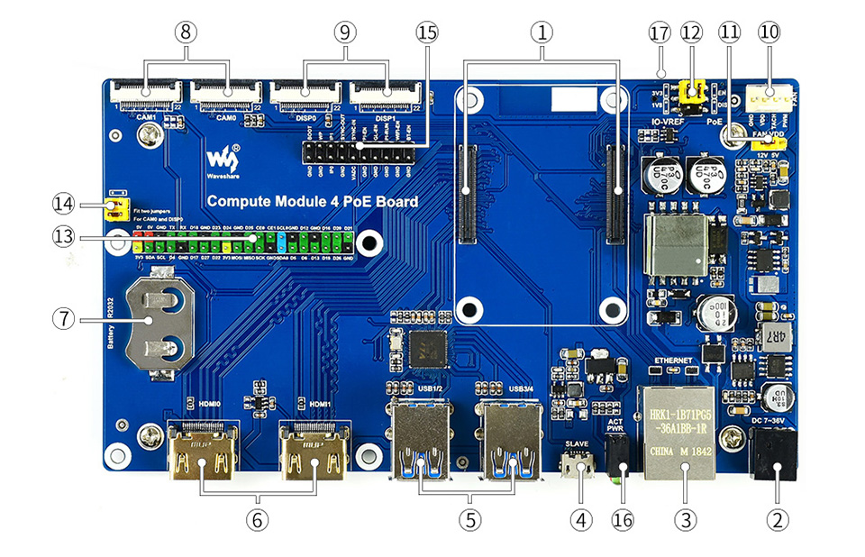
- CM4 socket: suitable for all variants of Compute Module 4
- Power input: 7~36V wide range power supply
- Gigabit Ethernet connector: Gigabit Ethernet RJ45 with PoE support
- USB SLAVE port: allows burning system image into Compute Module 4 eMMC variants
- USB3.2 ports: 4x USB 3.2 Gen1 ports, for connecting sorts of USB devices
- HDMI ports: 2x HDMI ports, supports dual 4K 30fps output
- RTC: RTC battery holder, allows RTC-related functions like wakeup, shutdown, reboot, and more
- CAM: 2x MIPI CSI camera ports
- DISP: 2x MIPI DSI display port
- FAN: for connecting cooling fan, allows speed adjustment and measurement
- FAN power selection: 5V or 12V voltage to drive the fan
- IO-VREF/PoE selection: CM4 IO logic level: 3.3V or 1.8V
PoE: enable (EN) or disable (DIS) - 40PIN GPIO header
- CAM0 and DISP0 I2C bus: fit the jumpers when using CAM0 or DISP0
- Misc configurations
- Dual LED indicators: red: Raspberry Pi power indicator, green: Raspberry Pi operating status indicator
- TF card slot (bottom side): insert a Micro SD card with pre-burnt system, to start up Compute Module 4 Lite
Outline dimensions
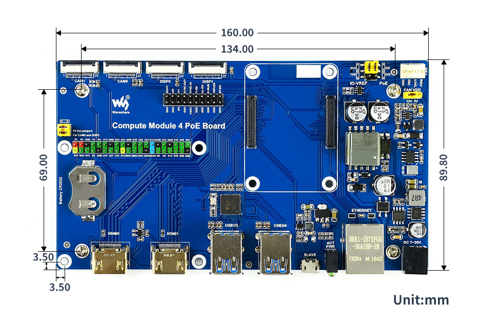
What's in the box?
1 x Compute Module 4 PoE Board
Resources
WIKI: Compute_Module_4_PoE_Board

These 0.4mm MK8 Nozzles are Creality Original replacement parts designed to fit the Creality CR-X, and are based on the successful MK8 design. They are the standard nozzle size of 0.4mm, which is the same size that comes equipped on many of the modern models since 3mm filament began phasing out. This size offers impressive accuracy without compromising too much on the rate at which 3D Printers lay down the Plastic Filaments – A good balance of speed and quality that is relatively easy to work with compared to larger or smaller nozzles.
While some people enjoy printing with smaller nozzles to ascertain even better quality and printing accuracy, and others choose to use large nozzles for speed-printing models or objects that don’t need to be perfectly accurate, these nozzles offer the best of both worlds. This is why they come as the stock nozzles on so many different models of printers. However, if you are a veteran in 3D Printing, you will understand that each different size nozzle can offer their own benefits
Package includes:
1 x 0.4mm nozzle for CR-X

Great for short distance extension
Specifications:
Material:PVC
Length:1000mm(approx)
Colour: Black
Package includes:
1 x DC 5.5 x 2.1mm Male To 5.5 x 2.1mm Female Power Cable

This LCD accepts 8-bits/9-bits/16-bits/18-bits parallel interface, that are RGB444, RGB565, RGB666. The color format used in demo codes is RGB565.
This LCD uses a 4-line SPI interface for reducing GPIO and fast speed.LCD
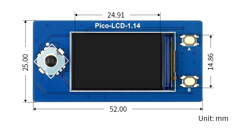
Features at a glance
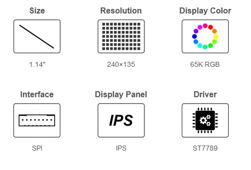
- 240×135 resolution, IPS screen, 65K RGB colors, clear and colorful displaying effect
- SPI interface, requires minimal IO pins
- 1x joystick and 2x user buttons for easy interacting
- Comes with development resources and manual (Raspberry Pi Pico C/C and MicroPython examples)
Specifications
| Operating voltage | 2.6 ~ 5.5V | Resolution | 240×135 pixels |
|---|---|---|---|
| Communication Interface | 4-wire SPI | Display size | 24.91 × 14.86mm |
| Display Panel | IPS | Pixel size | 0.1101 × 0.1035mm |
| Driver | ST7789 | Dimensions | 52.00 × 25.00mm |
Raspberry Pi Pico header compatibility
- Onboard female pin header for direct attaching to Raspberry Pi Pico
- 1x joystick and 2x user buttons for easy interacting
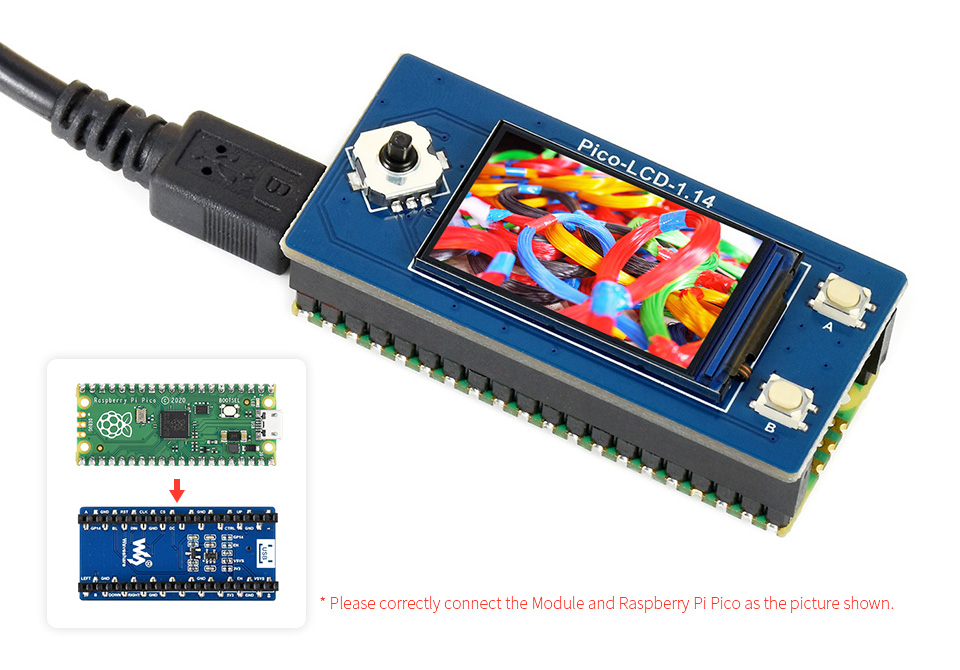
Raspberry Pi Pico is NOT included.
Pinout definition
Outline dimensions
What's in the box?
1 x 1.14inch LCD Display Module for Raspberry Pi Pico
Resources

Features
- Mecer Optical Wheel Mouse : USB
- Ergonomic design
- Light
What's in the box?
1 x USB optical Mouse

- High performance intelligent multi-frequency scanning use active matrix Thin film transistor liquid crystal display (TFT), LED backlight
- Comply with VESA DPMS International Power Saving Regulation
- Support DDC 1/2B and Windows PNP Plug & Play
- Microprocessor based with OSD (On Screen Display) control, able to adjust the image to optimum
- Complying with International Standard (VESA) to mount the display on the wall
- 19.5" (49.53cm) 16:9 wide LED
- Resolution 1600x900@60Hz
- Brightness 250cd/m²
- Viewing Angle 90°/65°(H/V)
- Net weight 2.14kgs
- Gross weight 3kgs
- Ultra slim
What's in the box?
1x LED monitor (with pedestal)
1x VGA signal cable
1x Audio cable
1x Power cord cable
1x User manual

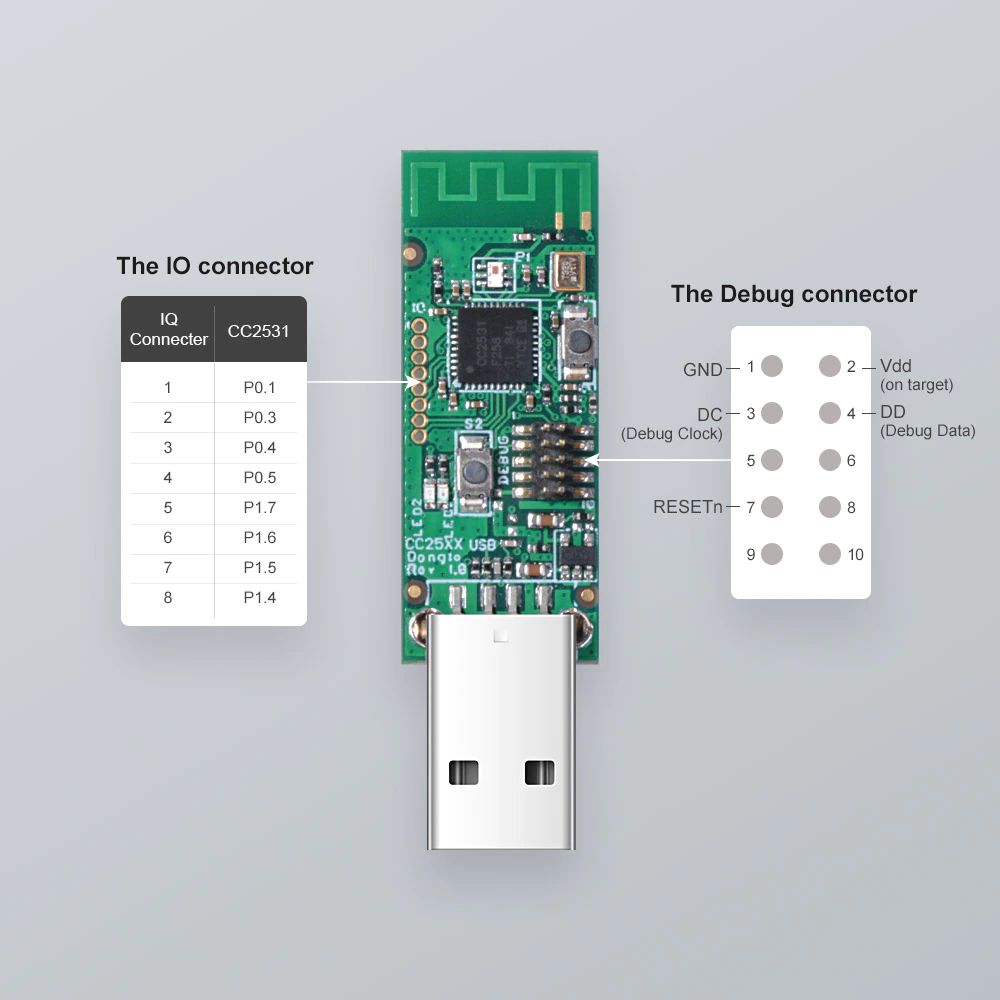
Features
Flashed with CC2531ZNP-Prod firmware for zigbee2mqtt application Lead out 8 IO connectors Debug interface Size: 5.6*1.6*0.7cm Two buttons and two LEDs for user interaction.
What's in the box?
1 x Sonoff Zigbee dongle