
Special Offers

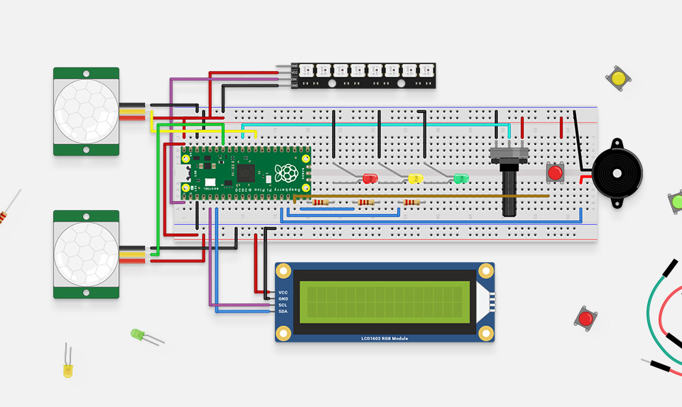
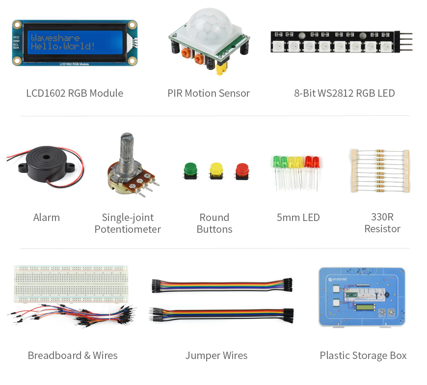
Basic entry-level kit prepared for Pico. All the parts you need to complete the tutorials in the MicroPython beginners book (not included)
Tested and selected by professional engineer, with rich tutorials and resources
fast getting started with Raspberry Pi Pico and MicroPython programming
A Low-Cost, High-Performance Microcontroller Board With Flexible Digital Interfaces
- RP2040 microcontroller chip designed by Raspberry Pi in the United Kingdom
- Dual-core Arm Cortex M0 processor, flexible clock running up to 133 MHz
- 264KB of SRAM, and 2MB of on-board Flash memory
- Castellated module allows soldering direct to carrier boards
- USB 1.1 with device and host support
- Low-power sleep and dormant modes
- Drag-and-drop programming using mass storage over USB
- 26 × multi-function GPIO pins
- 2 × SPI, 2 × I2C, 2 × UART, 3 x12-bit ADC, 16 × controllable PWM channels
- Accurate clock and timer on-chip
- Temperature sensor
- Accelerated floating-point libraries on-chip
- 8 × Programmable I/O (PIO) state machines for custom peripheral support
| Item | Description |
|---|---|
| LCD1602 RGB Module | LCD1602 RGB backlight character LCD, using I2C bus to display text or adjust RGB backlight |
| PIR motion sensor | Pyroelectric IR sensor, outputs electric switch signal when IR array from human/animal body is detected |
| 8-Bit WS2812 RGB LED | 8x RGB LED, play around with cool light effects by programming |
| Alarm | Quality active announciator, used for alarming or playing music |
| Single-joint potentiometer | Adjustable potentiometer, 0~10K range, used for ADC test, volume/brightness adjustment, etc. |
| Round buttons | Three colors, for button/switch detection |
| 5mm LED | Three colors, for experiments like traffic light, PWM adjusted light, etc. |
| 330R resistors | Providing current-limit protection when connected with LED in series |
| Breadboard and wires Jumper wires | Quality 830 breadboard and sorts of wires, easy for connecting components |
| Plastic box | Customized box for storing the modules and components |

Built especially to showcase the low cost, feature-rich RP2040 chip on the Raspberry Pi Pico, this board has VGA output, an SD card slot, digital I2S audio output, and more!
Based on the reference design by Raspberry Pi, our Pimoroni Pico VGA Demo Base is a great way to start experimenting with Raspberry Pi Pico/RP2040. It's the perfect way to demo of some of the fun things you can achieve with the RP2040 microcontroller such as generating a solid VGA output without taxing the CPU at all!
- Amaze your friends by showing them you still own a D-sub cable!
- Bask in the glory of 15-bit analog video!
- Get teary eyed over the warm, authentic, RC filtered PWM audio!
This board will run the various video example programs that Raspberry Pi have put together to demonstrate features of the RP2040.
Please note that VGA Demo Base only currently works with the C/C Pico SDK!
A Raspberry Pi Pico is not included - click here if you'd like to buy one!
Your Pico will need to have male headers soldered to it (with the pins pointing downwards) to attach to our add-on boards.
Features
- 15-pin VGA (D-sub) connector
- PCM5100A DAC for line out audio over I2S (datasheet)
- PWM audio output
- SD card slot
- Reset button
- Female headers to install your Raspberry Pi Pico
- Three user-controllable switches
- Rubber feet
- Compatible with Raspberry Pi Pico
- No soldering required (as long as your Pico has header pins attached)
- Programmable with C/C
What's in the box?
1 x Pimoroni Pico VGA Demo Base
Resources
Getting started
The pin-out of our board is the same as Raspberry Pi's reference board, you can find it in chapter 3 of Hardware Design with RP2040 along with more general info about the VGA reference board.
To run the audio and video examples in Raspberry Pi's experimental repos, first make sure you have up to date versions of pico-extras and pico-playground. When building the examples, you will need to specify the board configuration so that the examples use the correct pins. You can do this by creating a new build directory and then specifying the board definition when using cmake:
cmake -D"PICO_BOARD=vgaboard" ..
There's more details on about how to build applications with custom board configurations in Appendix D / page 267 of the C/C SDK documentation.
Pinout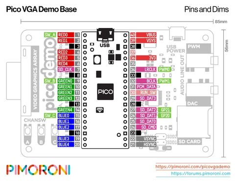

- Designed with nixie tube display.
- MCU controlled temperature calibration with PID system equipped, adjustable
- Temperature selection using knob, easy to operate.
- Combined soldering station with soldering stand.
- The handle structure is ergonomically designed for comfortable grip.
- The heating wire and sensor are made of PTC material, which is quick in
- Temperature rise and precise in temperature control.
Specifications
- Voltage: 110/220 VAC
- Power: 80W
- Temp Range 80°C ~ 480°C
What's in the box?
1 x Atten ST-2090D Soldering Station

Specifications
- Length 1000mm
- PG2020
What's in the box?
1 x 1m Extrusion

The kit includes our Foundation Plate which attaches to your pi-top [4]. Plug components into the foundation plate and get started right away, following step-by-step tutorials to learn the basics of coding and physical computing. Then continue your learning by progressing into projects in advanced coding, robotics, cybersecurity, and AI.
What's in the box ?
You will need a pi-top [4] or an essentials kit to use our Sensor Foundation Kit.
The Sensor Foundation Kit includes:
|
|

Note: We have tested this unit successfully on Zero and Zero 2.
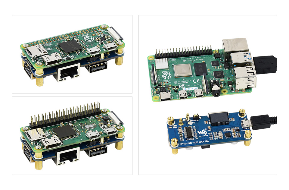
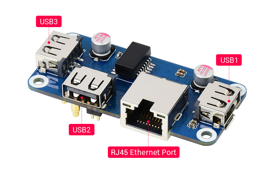
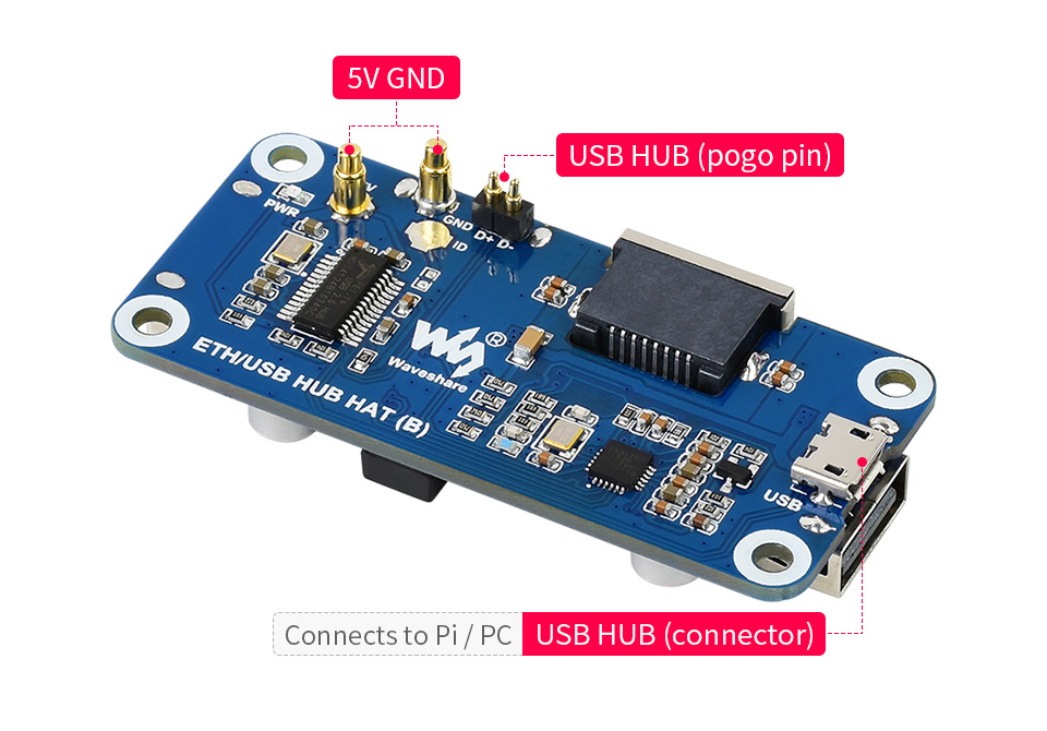
The ETH/USB HUB HAT (B) is an Ethernet and USB HUB designed for Raspberry Pi, providing 1x RJ45 Ethernet port and 3x USB 2.0 ports. It's pogo pin design is specialized for Zero series, while the onboard normal USB connector can be used to connect with other Raspberry Pi boards through a USB cable.
Specifications
- 3x extended USB ports, compatible with USB 2.0 / 1.1
- Incorporates RTL8152B Ethernet chip, supports 1x RJ45 Ethernet port, 10/100M auto-negotiation
- Pogo pin design, for direct connecting with Raspberry Pi Zero/Zero W/Zero WH
- USB HUB connector, for connecting with Raspberry Pi 4B/3B /3A /2B through USB cable
What's in the box ?
1 x ETH/USB HUB HAT (B)
1 x Screws and standoffs pack
Resources
Wiki: ETH/USB_HUB_HAT_(B)

Description:
The MonkMakes Solar Experimenters Kit for micro:bit is a project kit that allows you to experiment with harvesting energy from the sun and other light sources. It consists of a solar panel to harvest the energy, a solar store that stores the harvested energy, and a low energy light bulb and a motor that can be driven with the energy that you harvest.
Specifications:
There are three projects that introduce energy harvesting without the micro:bit, followed by 3 bigger projects that use the micro:bit (not provided) as an intelligent controller. The micro:bit monitors and manages the charging and discharging of the solar store.
With this project kit you will learn all about how tiny amounts of energy can be harvested from the sun and stored for later use, using a practical and experiment-led approach.
What's in the Box ?
1 x 10v Solar Panel
1 x Solar Store Board
1 x 3v LED light bulb
1 x Set of alligator clip leads (10 leads)
1 x Small motor with fan
1 x Booklet (A5)
Resources:
- Instructions (PDF)
- Data Sheet (PDF)
Lessons Plans are available here: https://drive.google.com/drive/folders/1o5tRY1PeU4N-NSVctra4NxnCvmP65Huj

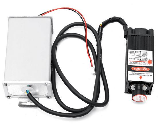
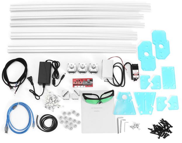
Specifications
- Material:stainless steel and acrylic
- Working Voltage:DC 12V
- Laser Power:3000mW
- Engraving Area:65x50cm(maximum)
- Unit Size:720mm x 630mm
Control software: benbox software support, power can be adjusted, weak light positioning
Engraving Material Note:
- can engrave materials: wood, bamboo, plastic, paper, leather, bank card, rubber
- can not engrave material: metal, stone, ceramic, shell, light-reflecting material, transparent material
Cutting Material Note:
It can only cut foam, paper, thin leather material.
Please Note:
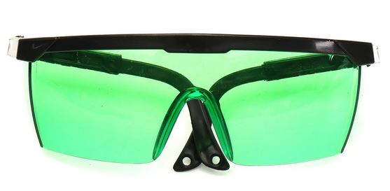
- In the process of using, please ALWAYS wear professional protective glasses to PROTECT YOUR EYES.
- FORBID CHILDREN to use this product.
- Yes, the laser WILL BURN YOUR SKIN! Be very careful while focusing the laser.
- Avoid the use of flammable objects or gasses near the engraver in order to avoid causing a fire or explosion. Never leave the unit unattended while engraving.
- Don't update the firmware.
What's in the box?
1x DIY Desktop Mini Laser Engraving Machine
You might also be interested in....
- A honeycomb bed for your laser engraver
Assembly instructions
https://www.youtube.com/watch?v=7jj5ea1MvEo

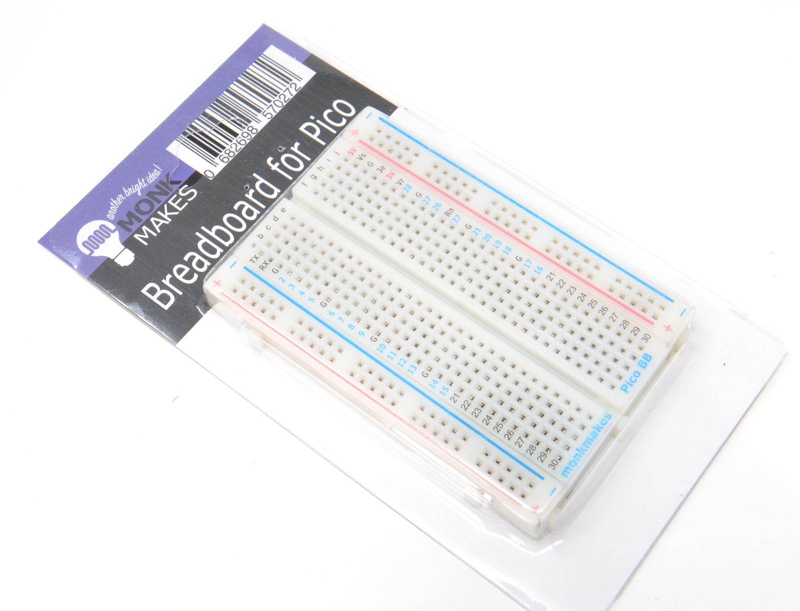
Specifications
- 400 tie point
- 2 power busses
- Size 8.2x5.5x0.85cm
- Self-adhesive back
- Electrical Characteristic Units Accepts wires and legs 20-29 AWG Maximum voltage AC/DC 50 V Maximum Current 2 A
(WARNING: Low voltage, low current usage only. Maximum 50V at 3A.)
What's in the box ?
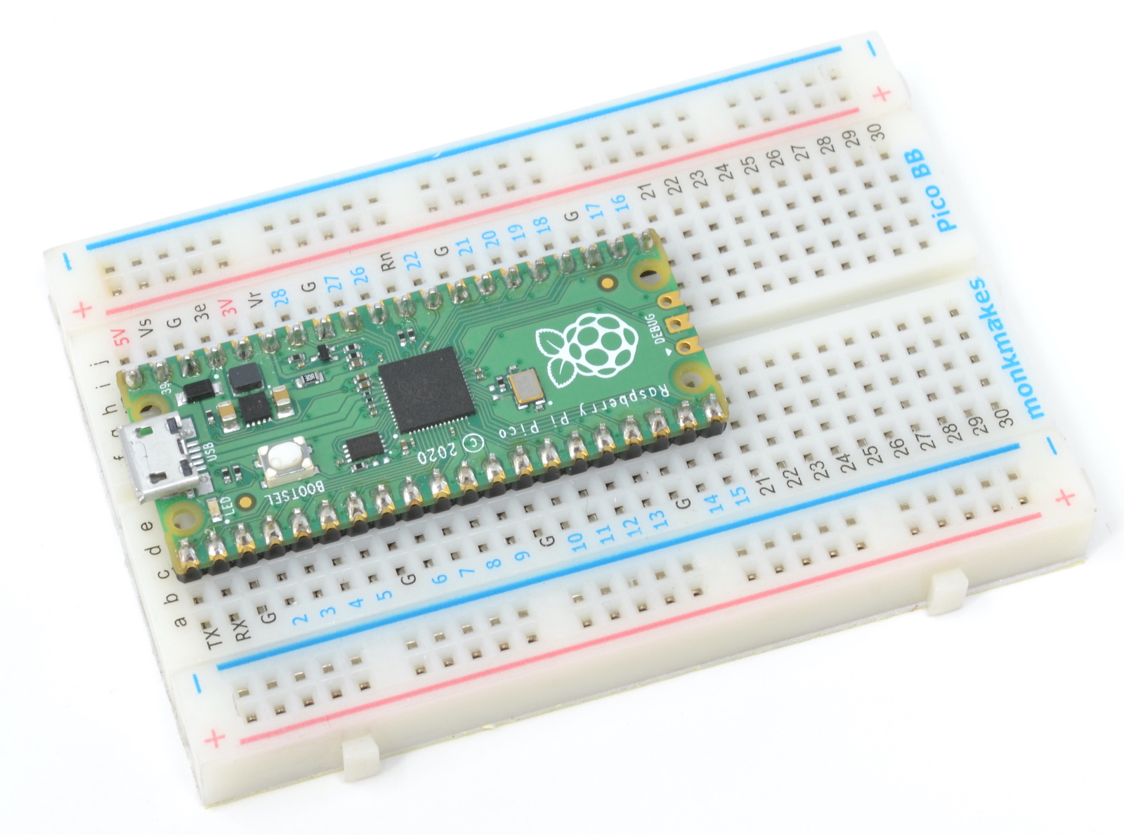
1 x Breadboard for Raspberry Pi Pico
(*Raspberry Pi Pico not included)
Resources
(*Raspberry Pi Pico not included)

Specifications
This kit is an improved and updated version of the now retired Electronics Starter Kit for Raspberry Pi
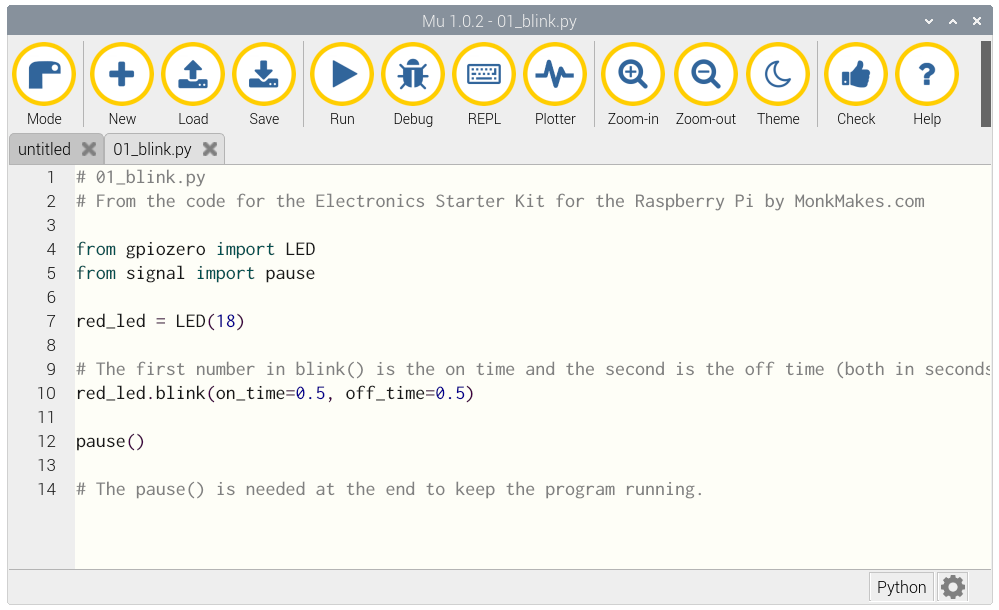
A 40 page booklet by Simon Monk (author of the Raspberry Pi Cookbook and Programming Raspberry Pi) is free to download and explains how to use the kit and build the projects.
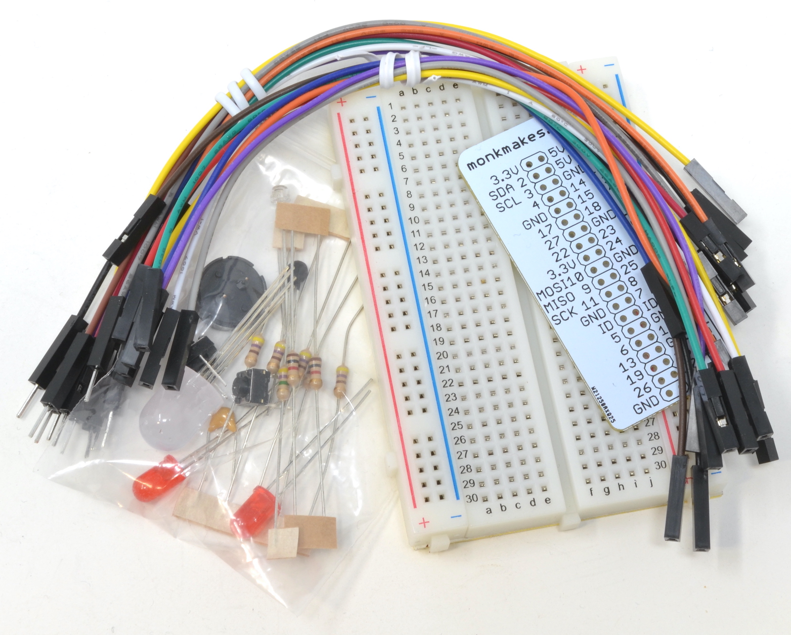
What's in the box ?
1 x Solderless breadboard
1 x Male to male jumper wires
1 x Female to Male Jumper Wires
1 x Raspberry Leaf
5 x 470Ω resistor (yellow, purple, brown stripes)
2 x 1kΩ resistor (brown, black, red)
1 x 4.7MΩ resistor (yellow, purple and green stripes)
1 x 330nF capacitor
2 x Red LED – the longer lead is the (positive) lead
1x RGB LED – the longest lead is the – (negative) lead
2 x Tactile push switch
1 x Phototransistor
1 x Thermistor
1 x Buzzer
You may also need....
Raspberry Pi is NOT INCLUDED
Resources
Instructions (PDF)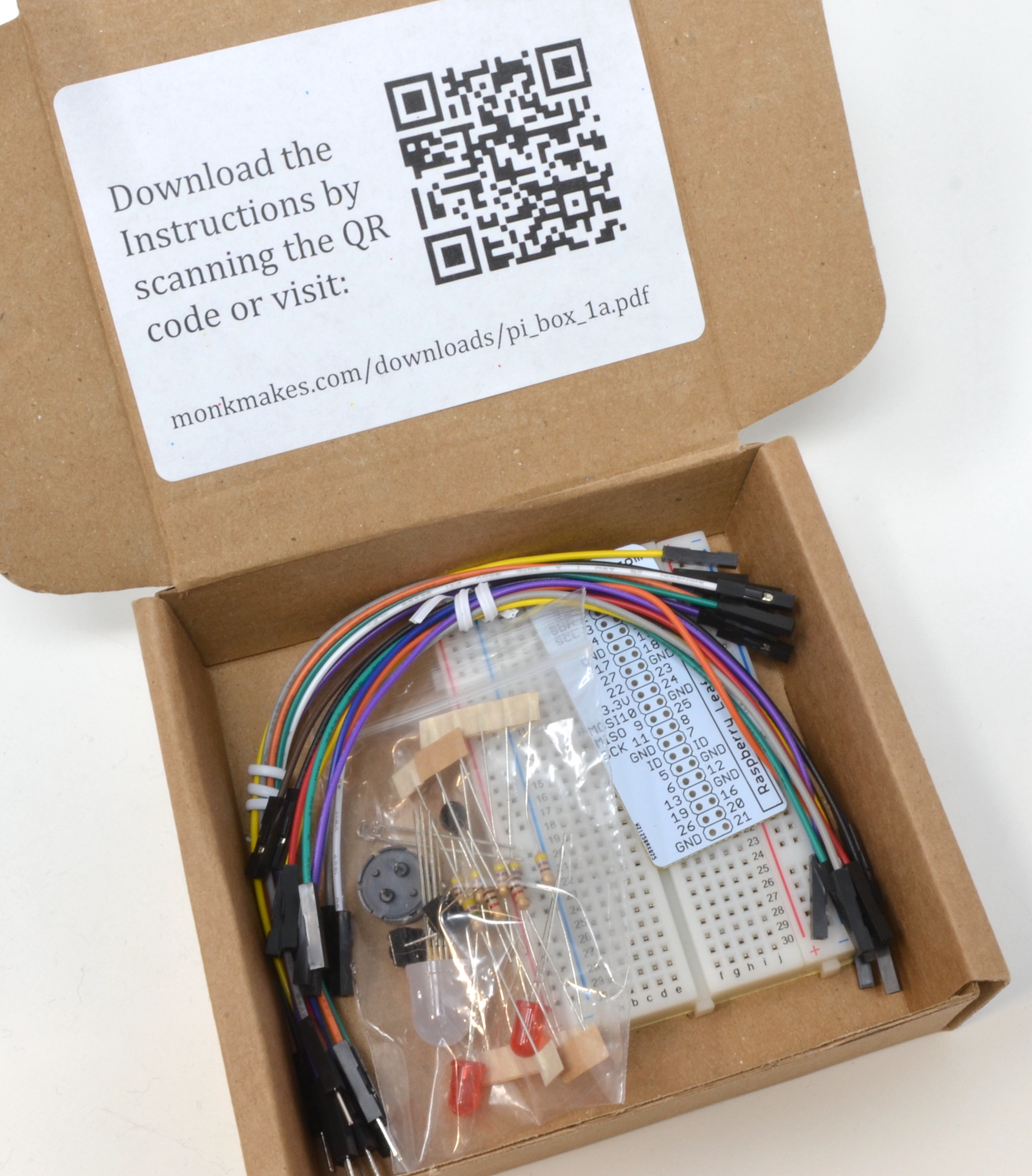

This is a wireless soil moisture sensor with a monitor(display). The soil moisture sensor will detect the data, then transmit to the receiver(display) wirelessly(433Mhz).
Function:
- 12/24hr digital time display
- Current soil moisture.
- Every 70 second the unit will receive soil moisture sensor.
- Wireless Signal Strength Indicator.
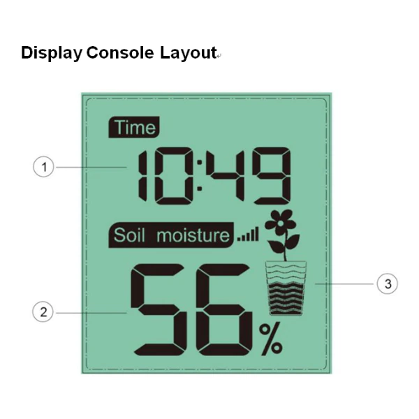
1. Time Display
2. Soil Moisture Value Display
3. Soil Moisture Grade Display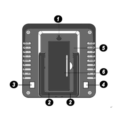
1. Hanging Hole
2. Tabletop Stand
3. ADD+ Button
4. Set Button
5. Battery Compartment
6. Battery Compartment Cover
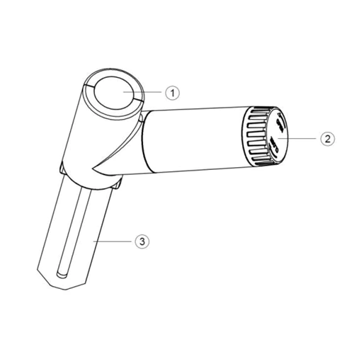
1. LED Indicator (RF transmission)
2. Battery Cap
3. Soil Moisture Sensor
Power requirement:
- Base station (display console) : 1 x AA 1.5v battery (not included)
- Remote sensor : 1 x AA 1.5v battery (not included)
Specifications
- Moisture Range: 0~100%; Resolution: 1%
- 0% AD setting range: 70~200; Initial value:70
- 100% AD setting range: 0% AD+10~1000; Initial value:500
- Frequency: 433 MHz
- Update Rate: 70 seconds
- Power Consumption: approx. 1 Year battery life.
1 x Soil Moisture Monitor (Receiver)
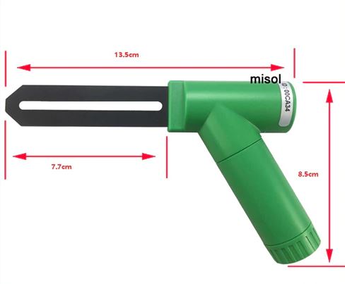
1 x Soil Moisture Sensor (transmitter)
1 x User Manual(in English)

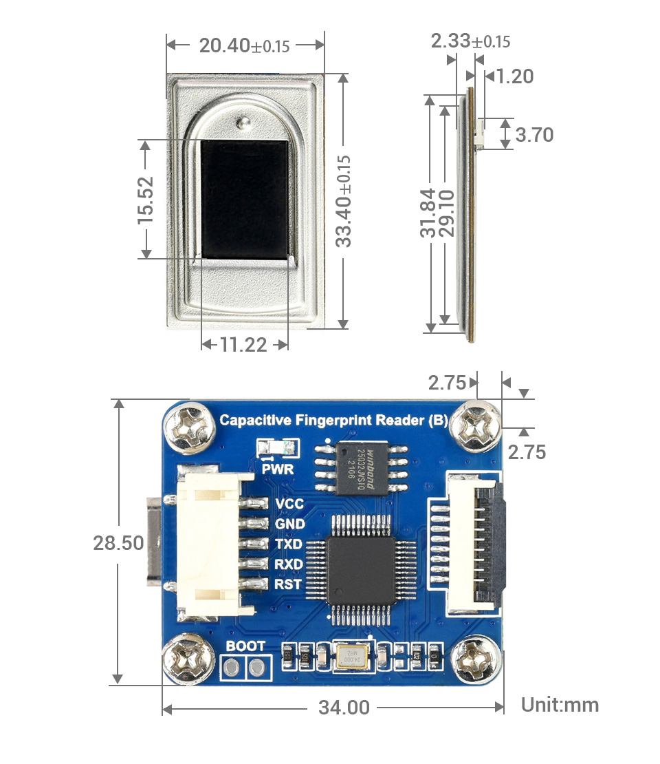
The Capacitive Fingerprint Reader (B) is a fast and stable capacitive fingerprint module specialized for secondary development, suits integration applications.
By incorporating high performance Cortex core processor, high security commercial fingerprint algorithm, and advanced semiconductor fingerprint sensor, this module is designed as a intelligent integration module with functions including fingerprint enrolling, image processing, template generating and storing, fingerprint matching and searching, etc.
- Easy to use by some simple commands, you don't have to know any fingerprint technology, or the module inter structure/calculation
- Commercial fingerprinting algorithm, stable performance, fast identification
- Sensitive detection, just touch the collecting window lightly, without pressing
- Allows to freely input/output fingerprint images, fingerprint feature file and other fingerprinting actions
- Dual communication, UART or USB
- Comes with rich development resources (related command documents, tools, and examples for Raspberry Pi/Arduino/STM32)
| parameter | value |
|---|---|
| Sensor | Semiconductor (capacitive) |
| Module dimension | 34 × 28.5mm |
| Sensor dimension | 33.4 × 20.4mm |
| Image | DPI 508 |
| Image resolution | 208 × 288 |
| Greyscale | 256 (8-bit) |
| Sensing area | 14.6 × 10.6mm |
| Fingerprint capacity | 3000 |
| Security level | 1-5 configurable, 3 by default the higher value, the lower FAR (False Acceptance Rate), yet the higher FRR (False Rejection Rate) |
| Encryption key | 64-bit encryption |
| Image collecting rate | 20fps |
| Matching time | 0.5s |
| Dynamic current | <40mA |
| Operating voltage | 3.3-5V |
| Communication port | UART or USB |
| ESD | SD IEC 61000-4-2 LEVEL 4 positive/negative 15KV air discharge |
| Baudrate | configurable: 9600, 19200, 38400, 57600, 115200, 230400, 460800, 921600bps 115200bps by default |
Outline dimensions
What's in the box?
1 x Capacitive Fingerprint Reader (B)
1 x PH2.0 5PIN wire
Resources
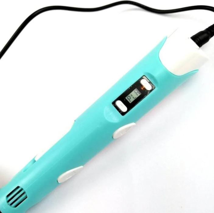
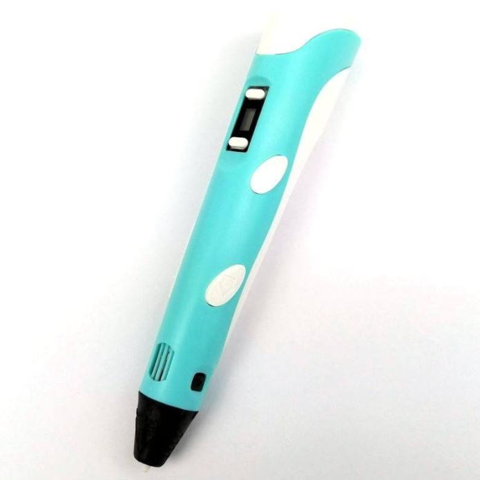
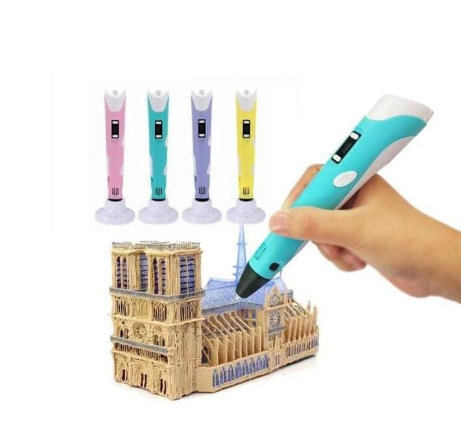
By using the 3D pen can actually help kids developing their artistic skills, spatial thinking, and can be a great creative outlet that engages their minds as they create. Besides, this 3D printing pen has a stable performance. It is more stable, safe and reassuring. Let your child fall in love with 3D printing.
Specifications
- Electrical Parameter: 12VDC 2A
- Comes with UK Plug, Universal (AC voltage and frequency) Adapter
- Can be used everywhere
- 3D printer for hand use
- Compatible with ABS and PLA filaments
- Diameter of filaments: 1.75mm
- Nozzle diameter: 0.7mm
- Heating Temperature:
- 160ºC - 210ºC (PLA)
- 210ºC - 235ºC (ABS)
- LCD for display filament type and temperature
- Adjustable filament feeding speed
- Ergonomic design, lightweight design, easy to operate
- Dimensions: 184mm x 31mm x 46mm
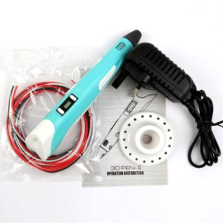
What's in the box ?
1 x 3D Printing Pen with PLA filament - Blu
1 x 3D Printing Pen stand
1 x UK Plug 12V 2A AdapterPLA
1 x Packet filament (3 random colors, 3 meters in total)
1 x User Manual/Operation Instruction
Resources
Want to print a spool holder that clips onto your 3D pen?
Check out Thingiverse
This device allows you to store and use lengths of 1.75mm filament for a 3D pen. The unique mini spool is designed to prevent the filament from unraveling under its own spring tension. The parts can be welded together with your 3D pen.
Check this link out to see what some people come up with :
3D printing pen

Develop your coding skills with the Kitronik :MOVE Motor for micro:bit, a fun introduction to buggies and robotics.
The Kitronik :MOVE Motor for the BBC micro:bit provides a fun introduction to buggy robotics. More than just a programmable buggy, learning to use all of the included features will give the budding roboteer a solid grounding in robotics as a whole.
Learn about movement, how to utilise light and sound, obstacle detection and avoidance, and how to code :MOVE Motor to follow a line. When used in conjunction with the micro:bit's radio features, the possibilities are endless.
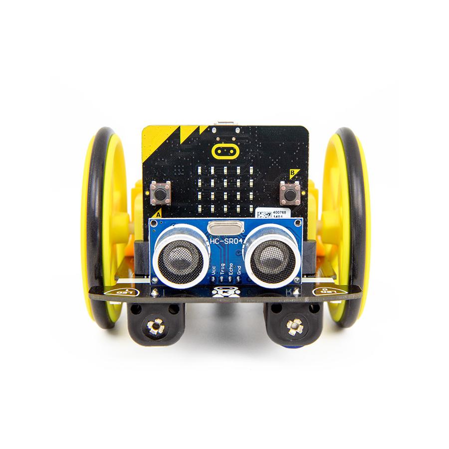
Attached to the chassis are two bi-directional DC motors with variable speed control. The wheels have rubber tyres and are a simple push-fit onto the motor shafts. Slot a BBC micro:bit into the edge connector and you are ready to code. There is no other assembly required and no tools required.
There are built-in battery holders for 4x AA batteries. This provides a regulated voltage supply to power the BBC micro:bit which is fed into the edge connector. There is also a power switch to conserve batteries when the buggy is not in use.
The micro:bit slots into the onboard edge connector. Code the micro:bit, plug it into the buggy, switch the power on, and then play.
CODE IT !
:MOVE Motor can be coded using the Microsoft MakeCode editor. Kitronik has produced a set of custom MakeCode blocks to simplify coding the completed buggy. The booklet that comes with the buggy contains more detailed instructions on using the blocks and writing code. If you are feeling more adventurous or relish a challenge, :MOVE Motor can also be coded with Python.
Also within the booklet (that comes inside the box), are some quick tutorials to get you started. There are also additional online tutorials and step by step guides for extra projects.
Note:- This kit does not include a micro:bit, a micro:bit can be obtained from here.
- No soldering is required!
- Minimal assembly required.
Specifications
| Length | 110mm. |
| Width | 90mm. |
| Voltage | Nominal 4.8 - 6V (4xAA batteries). |
| Motors | Pins 19 and 20 (via I2C). |
| Audio Buzzer | Pin 0 (Standard Music Pin). |
| Visual (4x ZIP LEDs) | Pin 8. |
| Line Follow (IR) | Pins 1 (Right) and 2 (Left). |
| Ultrasonic | Pins 13 (Trigger) and 14 (Echo). |
| Servo Connections | 2 on Pins 15 & 16. |
Features
- The Kitronik :MOVE Motor for the BBC micro:bit provides a fun introduction to buggy robotics and coding.
- It is backed up by a range of fun tutorials to introduce you to all of the great features.
- All of the tutorials and resources are free.
- There is no soldering required and assembly is quick and super simple.
- The buggy features two bi-direction DC motors.
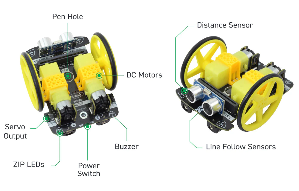
- There are ultrasonic distance and line following sensors onboard.
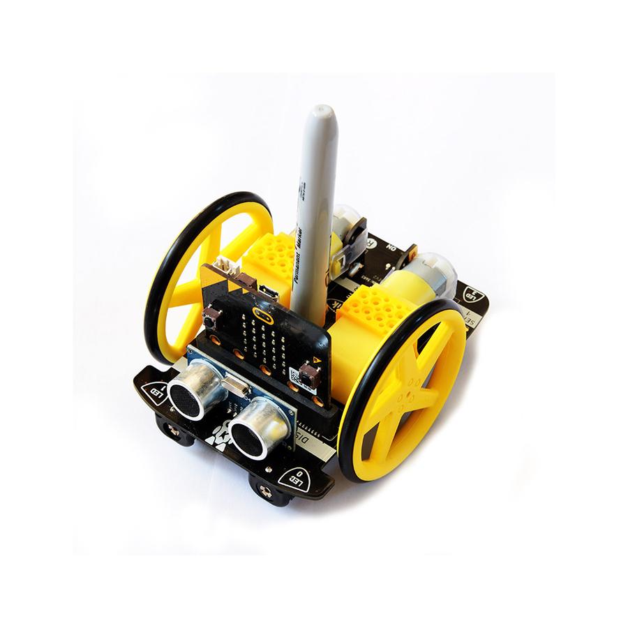
- It also features a Piezo sounder and pen mount.
- There are 4 full-colour programable ZIP LEDs.
- Two pin outputs that are ideal for servo connections (can be used for other inputs and outputs).
- The battery holder is built onto the chassis.
- The buggy is also fitted with a power switch to conserve the batteries.
- There is also an onboard edge connector for the micro:bit, code, plug and play.
- Kitronik has produced custom MakeCode blocks to simplify coding with the MakeCode editor.
What's in the box?
1 x :MOVE Motor chassis.
2 x Wheel and tyres.
1 x Booklet
You will also need....
1 x micro:bit
4 x AA batteries
1 x micro USB cable(to program the :MOVE)
Resources

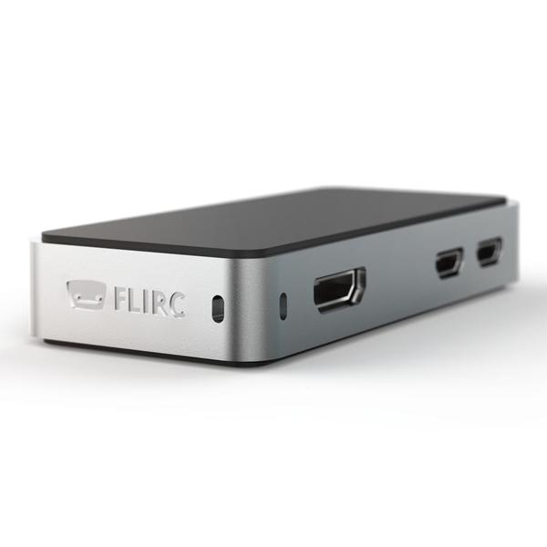
The FLIRC Raspberry Pi Zero Case is finally here - overly engineered, affordable and adorable!
The FLIRC Zero shares the same genetics as the original FLIRC case with some added features. FLIRC have kept everything that makes the original case great, shrunk it down, and added some nice elements that make this mini PC for every day carry.
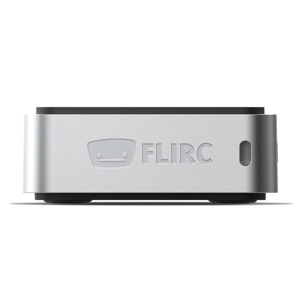
The familiar aluminium casing with a core heatsink and smooth top is there, offering silent, passive and efficient cooling combined with great looks.
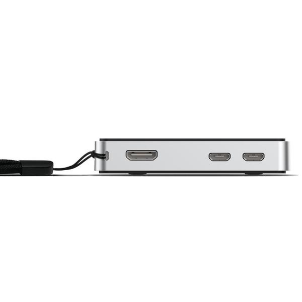
The SD Card is enclosed inside the case so it won't slip out or get stolen. The case needs to be disassembled before the SD card can be removed. There’s even a pre-installed lanyard included in the box in case you want to take your Zero somewhere other than the home.
Two top covers are included with the FLIRC Zero – allowing you to hide away and protect your GPIO, or leave it exposed for prototyping your projects. You can even add a pHAT without worrying about your Zero’s temperature.
What's in the box?
1 x FLIRC Zero Aluminum Case
1 x Thermal pad
2 x Top covers (sealed and GPIO access)
1 x Lanyard (pre-installed, removable)
Notes
1. The Raspberry Pi Zero’s LEDs are not visible with this case
2. Lanyard is removable (but fiddly to get back on)
3. Ships with a thermal pad – fit this to the case heatsink core before fitting your Raspberry Pi Zero
Which Pi Zero Models is the case compatible with?
The case will work with any Raspberry Pi Zero model, including the Raspberry Pi Zero 2 W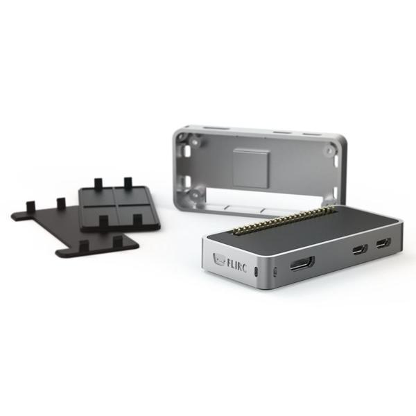

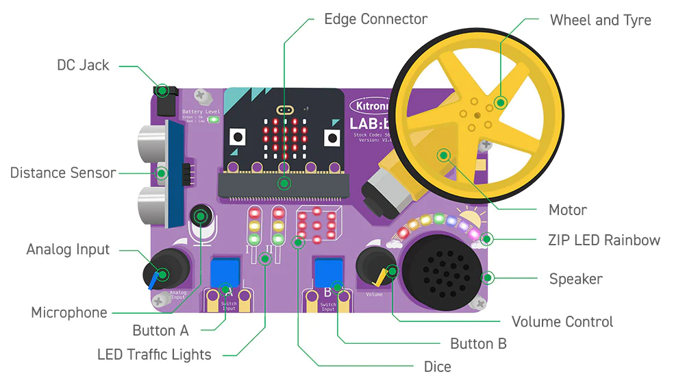
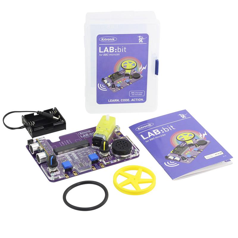
The Kitronik LAB:bit for the BBC micro:bit offers a super fun way for children to learn about coding in an engaging and hands-on way. It has been specifically designed for the classroom for KS2 computing and is backed by online MakeCode tutorials, simplified custom blocks, and a detailed getting started guide. Supplied in the box are; a battery holder (3 x AA), a wheel and tyre for the motor, and the detailed easy to follow guide.
The board is absolutely packed with an impressive array of features and devices for easy delivery of fun and informative lessons. These include; a motor, ultrasonic distance sensor, 2 x large user-assignable tactile buttons (with indicator LEDs), a microphone, speaker (with volume control), 7 programmable ZIP LEDs(in an arc), A user-assignable potentiometer control, 2 x sets of traffic light LEDs, and LEDs arranged in a dice formation (that can also be used for displaying digits).
The board also features; an edge connector for the micro:bit to slot into, a pre-fitted protective acrylic cover, clip-able pads for attaching an additional motor, 2 x clip-able pads for attaching further buttons/switches, Colour changing power indication LEDS, a cutaway for easy reset button access, and pre-fitted anti-slip rubber feet.
This all in one laboratory environment ships with a detailed getting started guide, filled with step by step information that can easily be followed by either teacher or pupil. The guide starts with an introduction to using a micro:bit and the MakeCode editor, with each explained in detail. This is then followed by instructions for fitting the wheel to the motor. Each area of the board is explained in detail, complete with code examples for each. As with the previous sections, this part of the booklet has been designed so that it can be used by teachers and pupils.
Coding is done via the MakeCode blocks editor. Kitronik has produced custom blocks for the editor to ensure that they are suitable for use with pupils aged 7-10. Each area of the board has its own blocks that all slot together in intuitive ways and they have been organised into subdirectories by type. For example, all of the blocks for the motor are in one submenu and blocks for the traffic lights are in another submenu. There is also an 'other' submenu that contains blocks for the more advanced/older students who require an extra level of challenge. Detailed information on how to add these blocks to MakeCode can be found in the Getting start guide that ships with LAB:bit.
Power is provided via the provided 3 x AA battery holder into the DC barrel jack input. The board has been rated for a maximum of 6V and a minimum of 3V, 3V - 4.5V recommended. The onboard power regulation circuit provides power to the board and to the micro:bit, removing the need to power the micro:bit separately. LAB:bit has an inbuilt polarity protection circuit for the DC input. There is a Colour changing power LED to indicate when the battery voltage is getting low.
- No soldering.
- Minimal mechanical assembly required. The wheel needs to have the tyre fitted and then to be fitted to the onboard motor.
- This kit is not supplied with a micro:bit. The micro:bit is available separately here.
Features:
- LAB:bit is an all in one educational platform designed for the delivery of KS2 computing in the classroom (7 - 10-year-olds).
- It's packed full of devices, LEDs, switches, sensors, and other programmable features.
- It features an edge connector for the micro:bit to slot into, no tools required.
- LAB:bit is supplied with a pre-fitted protective acrylic cover.
- Additionally, there are clip-able pads for attaching an additional motor, 2 x clip-able pads for attaching further buttons/switches, colour changing power indication LEDs, and a cutaway for easy reset button access.
- There are also pre-fitted anti-slip rubber feet to ensure that LAB:bit stays securely on the desk.
- Code it with blocks in the MakeCode editor.
- Kitronik custom blocks to make coding more intuitive and straightforward.
- Custom blocks are grouped by type to make it easy to go straight to the blocks you need.
- No soldering!
- Minimal mechanical assembly required.
- Supplied in the box are; a battery holder (3 x AA) and a wheel and tyre for the motor.
- Power LAB:bit via the provided 3 x AA battery holder.
- The board is rated for 3V - 6V.
- It has an inbuilt polarity protection circuit for the DC input.
- The onboard power regulation circuit provides power to the board and to the micro:bit, removing the need to power the micro:bit separately.
- LAB:bit is supplied with a fully comprehensive getting started guide. It takes you through everything you need to know and can be followed by both teacher and pupils.
What's in the box ?
1 x Kitronik LAB:bit for the BBC micro:bit
1 x Yellow 5 spoke injection moulded wheel and rubber tyre.
1 x 3AA battery holder.
(* Micro:bit NOT Included *)
Requires the following :
- micro:bit
- USB cable for connecting the micro:bit to a computer.
- 3 x AA Batteries.
- Optional - 5V USB Power Supply (1A or more).
- 7 online MakeCode experiments that teach you how to create code for each area of the board, they are.
- A Pirate ship for LAB:bit.
- Tech Talks - live stream playback.
- Insight Resources Mr Bit:
- LAB:bit downloads.
- Tutorial 1: https://youtu.be/3OMRCZJM5pc
- Tutorial 2: https://youtu.be/xndCctCDCdQ
- Tutorial 3: https://youtu.be/WyJ5bMPAGfg
- Tutorial 4: https://youtu.be/E7jYcPik43Y
- Tutorial 5: https://youtu.be/5pPr_XRS1cE
- Tutorial 6: https://youtu.be/5BDvlVw3M44
- Tutorial 7: https://youtu.be/6v39f_EWGcs
- Projects: https://youtu.be/fQBEHESlxQc
- Download Mr Bit,
(* Micro:bit NOT Included *)

By utilizing the new generation LoRa spread spectrum modulation technology, the communication distance of the module is as long as 5km, also supports auto repeating to transmit longer. Other features include Wake on Radio, wireless config, carrier sensing, communication key, and so on.
Comparing with normal LoRa modules, the SX1262 LoRa HAT achieves longer communication distance, higher rate, lower consumption, better safety and anti-interference. It is suitable for various applications such as industrial control, smart home, data collection, etc.
Features
- Standard Raspberry Pi 40PIN GPIO extension header, supports Raspberry Pi series boards
- Onboard CP2102 USB TO UART converter, for serial debugging
- Brings the UART control interface, for connecting host boards like Arduino/STM32
- 4x LED indicators, easy to check the module status
- LoRa spread spectrum modulation technology, up to 81 available signal channel, longer communication distance, more robust to interference
- Auto multi-level repeating, suit for ultra long range communication, allows multi network on the same region
- Low power consumption features like deep sleeping and Wake on Radio, ideal for battery-powered applications
- Customizable communication key which won't be retrieved, greatly improves the security of user data
- Supports LBT, monitoring the signal channel noise before transmitting, greatly improves the success ratio under extreme environment
- Supports RSSI signal intensity indicating, for evaluating signal quality, tuning the network
- Supports wireless parameter configuration, by sending wireless command/data packet, remotely configure or retrieve the module parameter
- Supports fixed-point transmission, broadcast, signal channel monitor
- Comes with development resources and manual (examples for Raspberry Pi/STM32)
What's on Board?
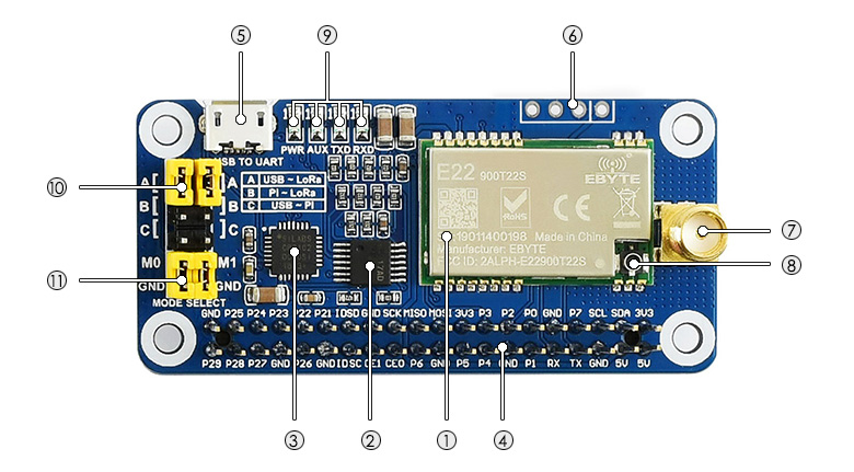
- SX1262 LoRa module
- 74HC125V: voltage level translator
- CP2102: USB TO UART converter
- Raspberry Pi GPIO connector: for connecting with Raspberry Pi
- USB TO UART port
- UART header: for connecting host boards like STM32/Arduino
- SMA antenna connector
- IPEX antenna connector
- Indicators:
- RXD/TXD: UART RX/TX indicator
- AUX: auxiliary indicator
- PWR: power indicator
- UART selection jumpers
- A: control the LoRa module through USB TO UART
- B: control the LoRa module through Raspberry Pi
- C: access Raspberry Pi through USB TO UART
- LoRa mode selection jumpers
- short M0, short M1: transmission mode
- short M0, open M1: configuration mode
- open M0, short M1: WOR mode
- open M0, open M1: deep sleep mode
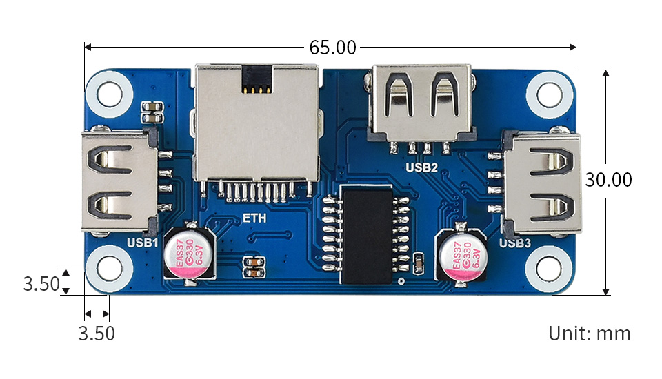
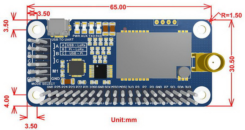
Dimensions
What's in the box ?
1 x SX1262 868M LoRa HAT
1 x USB type A plug to micro plug cable
1 x 868MHz antenna
Resources
Wiki : www.waveshare.com/wiki/SX1262_868M_LoRa_HAT

- This Micro SD Card Bundle for the Raspberry Pi consists of a SanDisk Class 10 UHS-I Micro SD card preloaded with Raspberry Pi OS
Please Note. This Micro SD Card does NOT come with a SD Card Adapter, it is the Micro SD Card ONLY
The SanDisk 64GB Preloaded Micro SD Card Features:- Superior Random-Access Performance - Perfect for the Raspberry Pi
- Capacity : 64GB
- Weight : Approx 0.2g
- Operating Voltage : 2.7 ~ 3.6V
- Speed Class 10 A1
- preloaded with Raspberry Pi OS 64bit
What's in the box?
1 x Sandisk 64GB preloaded micro SD card
Resources
Latest image available from the Raspberry Pi Foundation Downloads
Raspberry Pi OS documentation
Version updates
20/10/2023 Bookworm 64bit
10/07/2023 Bullseye

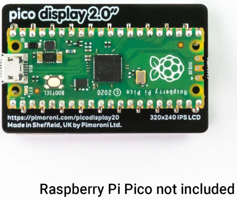
A spacious 2.0" (320 x 240) IPS LCD display for Raspberry Pi Pico, with four buttons, an RGB LED and plenty of room for your Pico projects!
This 18-bit capable 320x240 pixel IPS display adheres majestically to the back of your Pico, and has lush colours and great viewing angles. Just like our smaller Display Pack, we've surrounded it with four tactile buttons so you can use your human fingers (or other non-human appendages) to interface with your Pico. There's also an RGB LED that you can use as an indicator, for notifications or just for adding extra rainbows.
Pico Display 2.0 lets you turn a Pico into a user interface device for a bigger project, capable of giving instructions, displaying readouts and even incorporating elaborate nested menus. If you'd rather use your Pico as a standalone device you could fill up all that prime screen real estate with digitally generated, Mandelbrot-esque art, beautiful graphs or readouts from lots of sensors. You could even make a device for getting folks to share their secrets via Telnet!
A Raspberry Pi Pico is not included - click here if you'd like to buy one!
Your Pico will need to have male headers soldered to it (with the pins pointing downwards) to attach to our add-on boards.
- 2.0” 320x240 pixel IPS LCD screen (~220 PPI, 65K colours)
- 4 x tactile buttons
- RGB LED
- Pre-soldered female headers for attaching to Pico
- Compatible with Raspberry Pi Pico.
- Fully assembled
- No soldering required (as long as your Pico has header pins attached).
- Dimensions: approx 56mm x 35mm x 11mm (L x W x H, includes display)
- Screen usable area: 40.8mm x 30.6mm (L x W)
- C/C and MicroPython libraries
- Schematic
About Raspberry Pi Pico
Raspberry Pi Pico is a flexible, low cost microcontroller development board from the folks at Raspberry Pi, based on their very own chip - the RP2040. It's easily programmable over USB with C/C or MicroPython, and ideal for using in all sorts of physical computing projects, devices and inventions - we're so excited to see what you make with it!
We've called our Pico-sized add-ons packs, as they're designed to attach to the back of your Pico as if it were wearing a very stylish back pack (or a miniature jet pack, if you prefer). We've also got Pico bases (larger add-on boards with a space to mount your Pico on top) and some other boards that let you do interesting hackerly things like using multiple packs at once - click here to view them all!
What's in the box ?
1 x Raspberry Pi Pico display (320 x 240) IPS LCD
Resources
Getting started
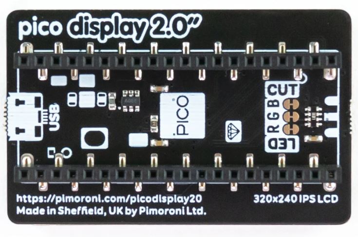
The labels on the underside of Pico Display will show you which way round to plug it into your Pico - just match up the USB port with the markings on the board.
The easiest way to get started is by downloading and copying our custom MicroPython uf2 to your Pico, it includes all the libraries you'll need to use our add-ons. Click here for our beginner friendly tutorial!
You can find C examples here and MicroPython examples here. You can also use it with CircuitPython!
Notes
- This screen is a wee bit taller than the surrounding buttons, so it's worth taking care when pressing the buttons that you're not also pressing down on the screen, particularly at the edge with the ribbon cable. Careful pressing with fingertips rather than full on thumb mashing is the way forward!
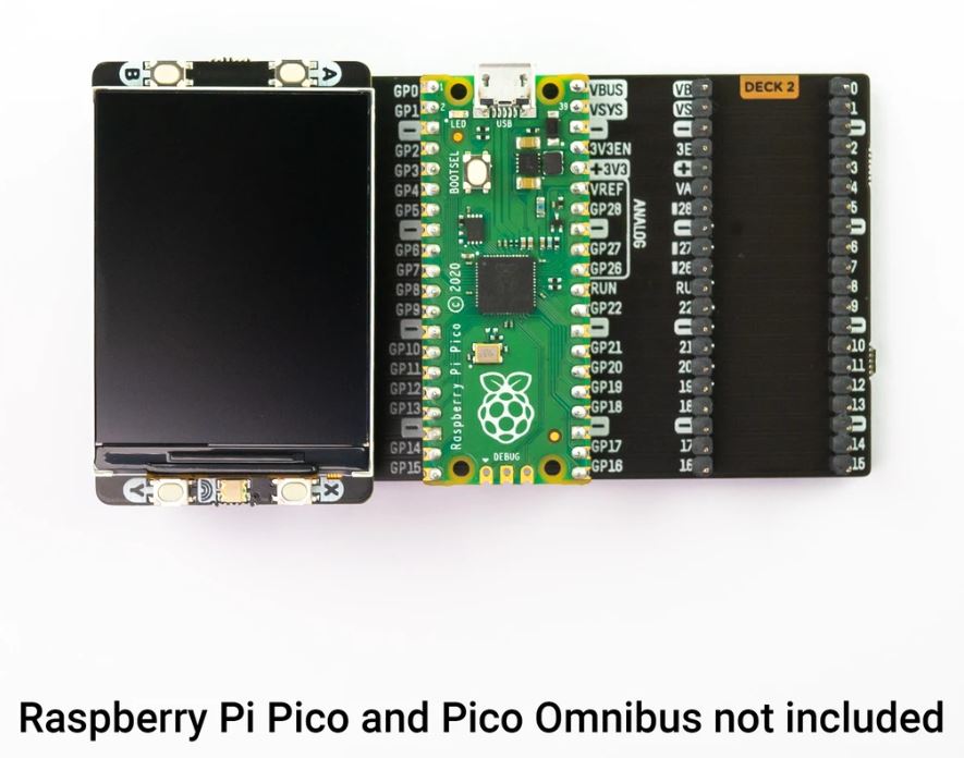
- Even though it's bigger than our other Pico Packs, Display 2.0 will still work with Pico Omnibus or Pico Decker, if you want to use more than one Pico Pack at once. Please note that if you plug Display 2.0 into a Pico Decker, it will overhang the addon slot next to it.

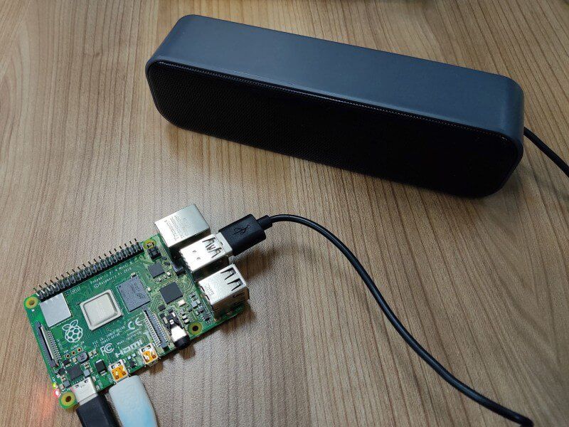
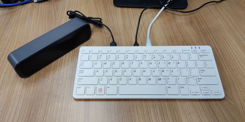
As the new Raspberry Pi 400 keyboard computer does not come with a 3.5mm Audio Barrel for speaker output, this USB powered, and signal is the perfect speaker for it. And we have tested it with Raspberry Pi 400, it works like expected. No driver is needed, plug and use!
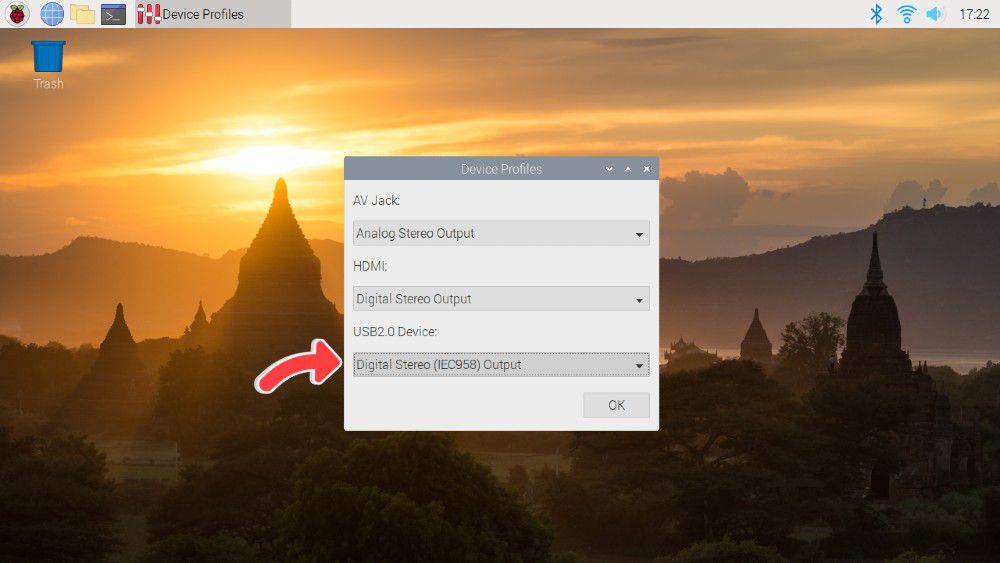
Note: If you're using the speaker with your Raspberry Pi, be sure to change the audio device to USB2.0 Device and change the output to Digital Stereo Output. Else, you will not be able to control the volume.
Features and specifications
- They are small and compact, so they can be brought anywhere.
- Powered by a single USB cable, have NO volume control knob, easy to use.
- Anti-interference and stereo sound.
- Crystal-clear treble.
- Space-saving design, they can be conveniently placed next to your PC monitors without compromising on valuable desk space.
- Built-in 2 speakers, balance and enhance the sound of your laptop, notebook, computer, PC, tablets, good for work, music, movies, games, etc.
- Acoustic quality stereo sound, let your room filled with music, movies, or computer games.
- No driver is needed for Windows, Linux and macOS, just plug and play!
- Great for
- Enhance any media experience while at home, office, kitchen, basement, or on the go.
- Upgrade to your computer's weakened or faint internal speakers. Perfect USB Speakers for Windows PCs, Desktop Computer, Laptop.
- Daily listening, static listening at home or office.
- Material: Plastic
- Output Power: 3W*2
- Channel: 2.0
- Frequency Response Range: 25Hz-20KHz
- Separation: ≥40dB
- Power Supply: USB 5V
- SNR: ≥80dB
- Voltage: 5V
- Connectivity: USB
- Number of speakers: 2
- USB Cable Length: 47 inches
- Connection radius: direct connection