
Special Offers

Features
- 3 tutorials
- MicroPython
- C (Compatible with Arduino IDE)
- Processing (Java))
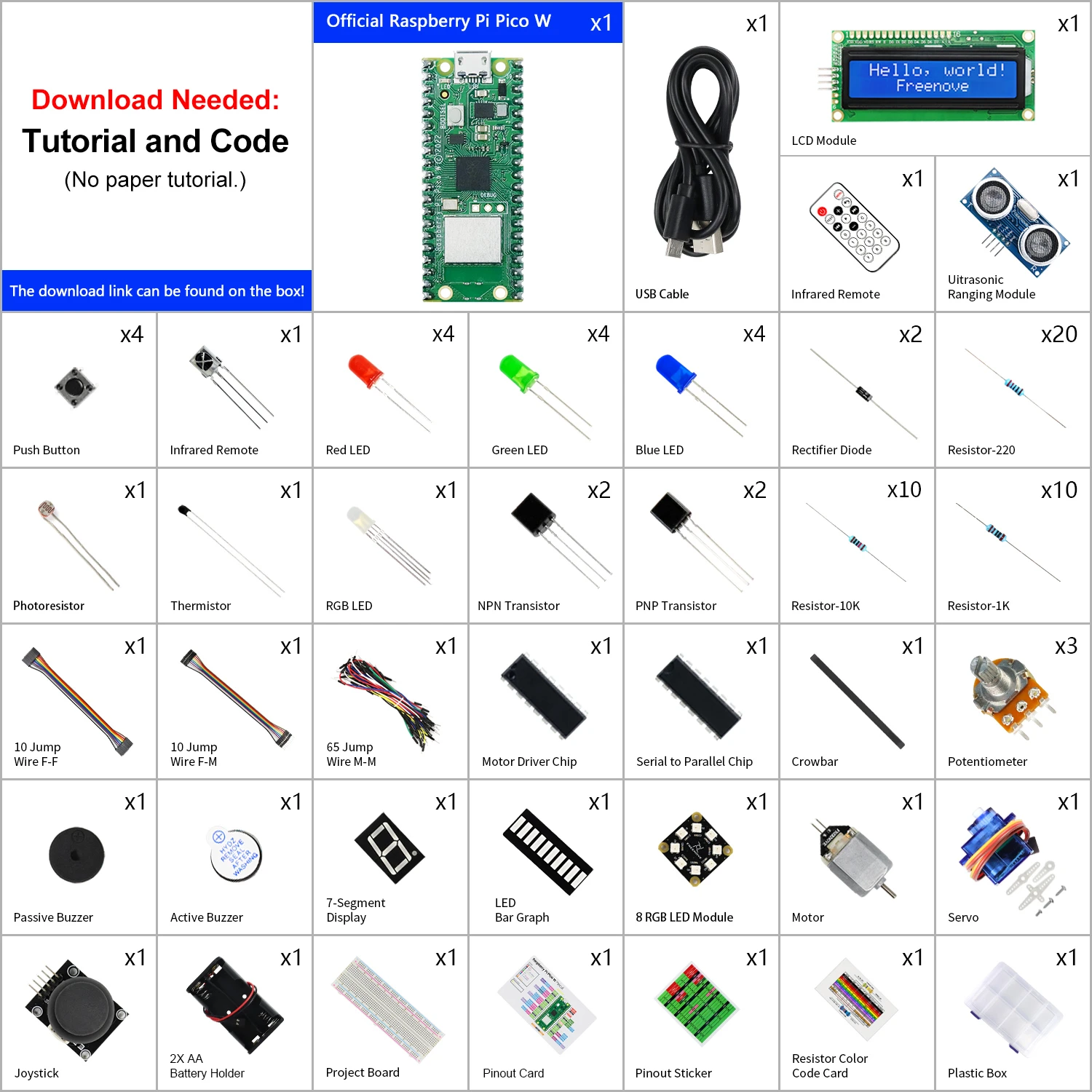
- 513-Page Detailed Tutorial - Comes with detailed tutorial including basic electronics knowledge. (Download needed, no paper tutorial.)
- 177 Items - All parts needed to complete the projects in the tutorial. No soldering required.
- 87 Projects - Each project has circuit diagrams and verified code with detailed explanations.
What's in the box?
Resources
Download tutorials here

- Note: MakerDisk MicroSD cards (128GB, 64GB, 32GB) shipped from 11 Nov 2021 onwards are loaded with the latest Raspberry Pi OS - Bullseye (release date: 30th October 2021).
Note: The MakerDisk microSD card has been TESTED and APPROVED by the Raspberry Pi Foundation for use with Raspberry Pi Products.
Note: The MakerDisk microSD card comes Pre-loaded with Raspberry Pi OS and is ready to boot up on any Raspberry Pi computer. Please DO NOT format it if you intend to use it with the Raspberry Pi board.
We have also performed the writing and reading speed diagnosis and the results exceed the requirement needed for Class A1 and also the specifications by the Raspberry Pi Foundation. So we are confident to recommend this microSD to you :)Note: There are 128GB, 64GB, and 32GB of capacity, please select your preferred memory size.
Features- Raspberry Pi Tested and Approved for use with Raspberry Pi Products
- A microSD card from Makers to Makers!
- Brand: MakerDisk
- Capacity/Size: 128GB, 64GB or 32GB
- 1GB = 1,000,000,000 bytes.
- Actual usable capacity may be less, depending on the format. From Raspberry Pi OS, here is the capacity from file explorer, excluding the boot drive:
- 128GB MakerDisk microSD: it is ~ 114.8GB
- 64GB MakerDisk microSD: it is ~ 56.9GB
- 32GB MakerDisk microSD: it is ~ 28.2GB
- Check the capacity calculation from Wiki.
- Pre-loaded with Raspberry Pi OS, it is ready to boot up on any Raspberry Pi board right out of the box!
- 11 November 2021 onwards, the latest Raspberry Pi OS - Bullseye, 3.1GB, (release: 30th Oct 2021) is preloaded
The test results are better than Class A1 and Raspberry Pi Standards:- 32GB MicroSD:
- Sequential Write: > 27MB/S (A1 Standard 10MB/S, Raspberry Pi Standard 12MB/S)
- Random IOPS - Write: > 800 IOPS (A1 standard 500 IOPS, Raspberry Pi Standard 500 IOPS)
- Random IOPS - Read: > 2700 IOPS (A1 standard 1500 IOPS, Raspberry Pi Standard 2000 IOPS)
- Class 10, A1, U1, V10 microSD card
What's in the box?
1 x Makerdisk 32GB preloaded micro SD card
Resources
Latest image available from the Raspberry Pi Foundation Downloads

Contents of kit
Scraper - With the plastic scraper, you can easily remove your finished models from the print platform.
Brush - The small brush makes it easier for you to clean your models and tools.
PVC gloves - PVC gloves protect you from contact with resin and should therefore be used whenever you use 3D printing resins.
Stainless steel and silicone funnel - The two wide-diameter funnels make resin recycling easier for you.
Silicone pad - The silicone pad (405 x 305 mm) keeps your table clean for all resin work.
What's in the box?
1 x Creality Resin tool kit

Please Note: Raspberry Pi is not included
The included fan is powered from the GPIO pins
This DIY case requires assembly. You will need a small precision flathead screwdriver. The fan is powered from GPIO.
Features
- Two-part Raspberry Pi case for Pi 3, Pi 4 and Pi 5.
- Easy access to all Pi connectors
- Open design to keep your Raspberry Pi cool
- You can mount a HQ cam onto this case. See the hint at the end of the description.
What's in the box?
2 x DIY Acrylic Case layers
1 x 30mm fan that gets powered from GPIO(Not the RPi5 fan adapter)
1 x 30mm fan grill
1 x flared processor heatsink
4 x 5mm standoffs
4 x 25mm standoffs
8 x M2.5x6 screws
4 x M3x16 screws
4 x M3 nuts
4 x rubber feet
As from 11/12/2023 we add a black heatsink (19x14x7) to this kit. You can now choose which heatsink fits your RPi processor best.
You might also like to add the RPi 5 fan that is OS controlled.
Case Assembly guide
1. Remove the acrylic protective film from the two plates
2. Install the standoffs first. Push the male part of the short standoffs through the RPi board mounting holes from the bottom upwards. Use the Female Female standoffs as nuts on the top of the RPi board.
3. Mount the fan and fan grill on the top acrylic plate.
4. Mount the top and bottom acrylic plates using the eight M2.5x8 screws.
5. Connect your fan power cable to the GPIO port.
Hint
Why are there four extra holes on the bottom plate?
If you buy four 5mm standoffs with M2.5 nuts and M2.5x4 screws, you'll be able to mount an HQ camera on the bottom plate of the case, on which you can then add a tripod.

Each knife has a different angle of the blade allowing for many types of cuts for multiple applications.
What's in the box?
3 x hobby knife handles
13 x blades
1 x enclosure

You can read more about CoderLevelUp and how they use this kit
This kit contains what you'll need to begin your Raspberry Pi adventure making use of the crafty projects contained in Introduction to Raspberry Pi Pico.
This kit can be used for many mini projects to help get you through that beginner stage. Follow along the detailed guide to starting off in the Raspberry Pi hobby to help support your journey even more.
Use this parts kit to build the following:
- an LED firefly
- a reusable party popper
- a papercraft beating heart
- a mood indicator
- a sound machine
- or a sensory gadget.
What's in the box?
1 x Raspberry Pi Pico H (pre-soldered headers)
1 x USB cable (USB A to micro B Red)
10 x 5mm LEDS (2x red, 2x blue, 2x yellow, 2x green, 2x white)
5 x RGB Diffused LEDs
10 x 100 Ohm resistors
1 x piezo transducer (can be used as a passive buzzer)
2 x PCM mount Potentiometer Finger Adjust Preset 10K
5 x 2 pin tactile push buttons(6x6x5mm)
20 x male to female jumper wires 20cm
20 x female to female jumper wires 20cm
Resources
You can find an overview of each of the six activities here.
| Activity Description. | ||
|---|---|---|
| LED firefly - In this project, you will use a Raspberry Pi Pico to make an LED firefly that flashes in a particular pattern, just like fireflies in nature, and connect a switch to control the light. | ||
| Party popper - Make a reusable party popper that rewards you with a light and sound display when it is pulled. | ||
| Beating heart - Make a papercraft beating heart with a pulsing LED and a dial to adjust the heart rate. | ||
| Mood indicator - Create a mood check-in device with coloured lights to emote your current mood. | ||
| Sound Machine - Create a sound machine that will play sound effects or music using buttons, switches, or a potentiometer. | ||
| Sensory gadget - Learn how to make a fidget toy or sensory gadget. |

Features
- 2K (3MP) High-Definition Video: Records all the details in crystal-clear 3MP definition.
- Pan/Tilt: 360º horizontal range.
- Advanced Night Vision: Provides a visual distance of up to 30 ft.
- Motion Detection and Notifications: Notifies you through Tapo App when the camera detects movement.
- Sound and Light Alarm: Trigger light and sound effects to frighten away unwanted visitors.
- Two-Way Audio: Enables communication through a built-in microphone and speaker.
- Safe Storage: Locally stores up to 256 GB on a microSD card, equal to 512 hours (21 days) of footage. (Based on laboratory conditions).
- Voice Control: Free Up Your Hands with Voice Control: Works with the Google Assistant and Amazon Alexa. (Google Assistant and Amazon Alexa are not available in all languages and countries).
SPECIFICATIONS
CAMERA
- Image Sensor: 1/2.8“
- Resolution: 3MP(2304 x 1296)
- Lens: F/NO: 2.4; Focal Length: 3.83mm
- Night Vision: 850 nm IR LED up to 30 ft
- View Range: 360° horizontal, 114° vertical
VIDEO
- Frame Rate: 15fps
- Video Streaming: 3MP
- Video Compression: H.264
AUDIO
- Audio Communication: 2-way audio
- Audio Input & Output: Built-in microphone and speaker
NETWORK
- Security: 128 bit AES encryption with SSL/TLS
- Wireless Rate: 11Mbps(802.11b), 54Mbps(802.11g), 72.2Mbps(802.11n)
- Frequency: 2.4 GHz
- Wireless Security: WPA/WPA2-PSK
ACTIVITY NOTIFICATIONS
- Input Trigger: Motion detection
- Output Notification: Push notification
SYSTEM
- Regulatory Certification: CE, NCC
- System Requirements: iOS 10+, Android 5.0+
ENVIRONMENT
- Operating Temperature: 0°C~40°C (32°F~104°F)
- Storage Temperature: -40°C~70°C (-40°F~158°F)
- Operating Humidity: 10%~90%RH non-condensing
- Storage Humidity: 5%~90%RH non-condensing
HARDWARE
- Button: Reset button
- Indicator LED: System LED
- Adapter Input: 100-240VAC, 50/60Hz, 0.3A
- Adapter Output: 9.0V/0.6A
- Power: 3 Meter Power Cable
- Dimensions (W x D x H): 3.4 x 3.3 x 4.6 in. (86.6 x 85 x 117.7 mm)
What's in the box?
1 x Tapo Pan/Tilt Home Security Wi-Fi Camera
1 x Power Adapter
1 x Quick Start Guide
1 x Mounting Screws
1 x Mounting Plate
1 x Camera Base
Resources
Overview, Setup and Support

Features
- 8× 10/100/1000 Mbps RJ45 ports.
- 4× PoE+ ports transfer data and power on individual cables.
- Works with IEEE 802.3af/at compliant PDs.
- Plug and Play, no configuration and installation required.
- 802.1p/DSCP QoS enable smooth latency-sensitive traffic.
- Supports PoE power up to 30 W for each PoE port.
- Supports PoE power up to 64 W for all PoE ports*.
- Up to 250m data and power transmitting range under Extend Mode**
- PoE Auto Recovery guarantees stable operation of PoE devices by automatically rebooting the dropped or unresponsive PD devices
Learn more about TP-Link PoE technology >
| HARDWARE FEATURES | |
|---|---|
| Interface | • 8× 10/100/1000 Mbps RJ45 Ports • AUTO Negotiation • AUTO MDI/MDIX |
| Network Media | • 10BASE-T: UTP category 3, 4, 5 cable (maximum 100m) • EIA/TIA-568 100Ω STP (maximum 100m) • 100BASE-TX: UTP category 5, 5e cable (maximum 100m) • EIA/TIA-568 100Ω STP (maximum 100m) • 1000BASE-T: UTP category 5, 5e, 6 or above cable (maximum 100m) • EIA/TIA-568 100Ω STP (maximum 100m) |
| Fan Quantity | Fanless |
| Physical Security Lock | Yes |
| External Power Supply | External Power Adapter(Output: 53.5VDC / 1.31A) |
| Packet Forwarding Rate | 11.904 Mpps |
| PoE Ports (RJ45) | • Standard: 802.3 af/at compliant • PoE Ports: Ports 1–4 • Power Supply: 64 W |
| Mac Address Table | 4K |
| Jumbo Frame | 16 KB |
| Switching Capacity | 16 Gbps |
| Dimensions ( W x D x H ) | 6.7×3.9×1.1 in (171×98×27 mm) |
| Max Power Consumption | • 4.7 W (220/50 Hz no PD connected) • 74.39 W (220/50 Hz with 64 W PD connected) |
| Max Heat Dissipation | • 16.03 BTU/h (no PD connected) • 253.67 BTU/h (with 64 W PD connected) |
| SOFTWARE FEATURES | |
|---|---|
| Transmission Method | Store-And-Forward |
| Advanced Functions | • Compatible With IEEE 802.3af/at Compliant PDs • IGMP Snooping • Mac Address Auto-Learning And Auto-Aging • IEEE802.3x Flow Control • 802.1p/DSCP QoS • Extend Mode Button (Ports 1–2, Up to 250 m PoE power supply and data transmission) • PoE Auto Recovery (Ports 1-4) |
| OTHERS | |
|---|---|
| Certification | CE, FCC, RoHS |
| Environment | • Operating Temperature: 0–40 ℃ (32–104 ℉); • Storage Temperature: -40–70 ℃ (-40–158 ℉) • Operating Humidity: 10–90% RH non-condensing • Storage Humidity: 5–90% RH non-condensing |
What's in the box?
1 x TL-SG1008P
1 x Power Adapter
1 x Installation Guide
Resources

Proud of your Raspberry Pi? Let the world know!
This eye catching sticker set will brighten up any laptop, desktop, monitor, car bumper, coffee machine, Anglepoise lamp, or anything else you can think of!
What's in the box?
1 x Set of 6 stickers

Proud of your Raspberry Pi? Let the world know!
This eye catching sticker set will brighten up any laptop, desktop, monitor, car bumper, coffee machine, Anglepoise lamp, or anything else you can think of!
What's in the box?
1 x Set of 6 stickers

Proud of your Raspberry Pi? Let the world know!
This eye catching sticker set will brighten up any laptop, desktop, monitor, car bumper, coffee machine, Anglepoise lamp, or anything else you can think of!
What's in the box?
1 x Set of 6 stickers
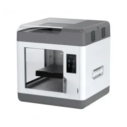
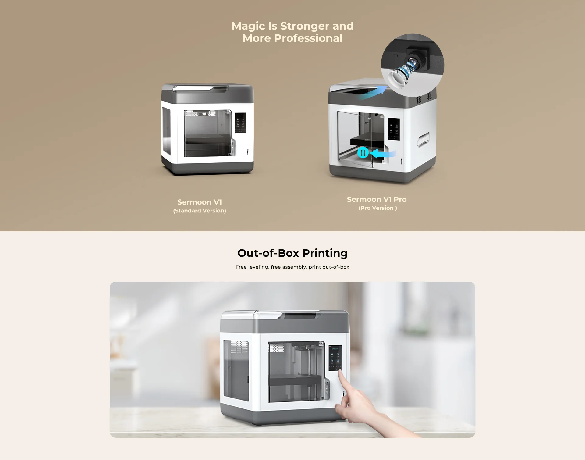
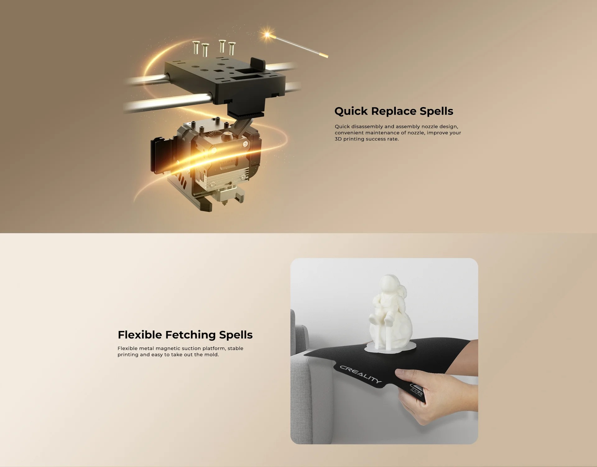
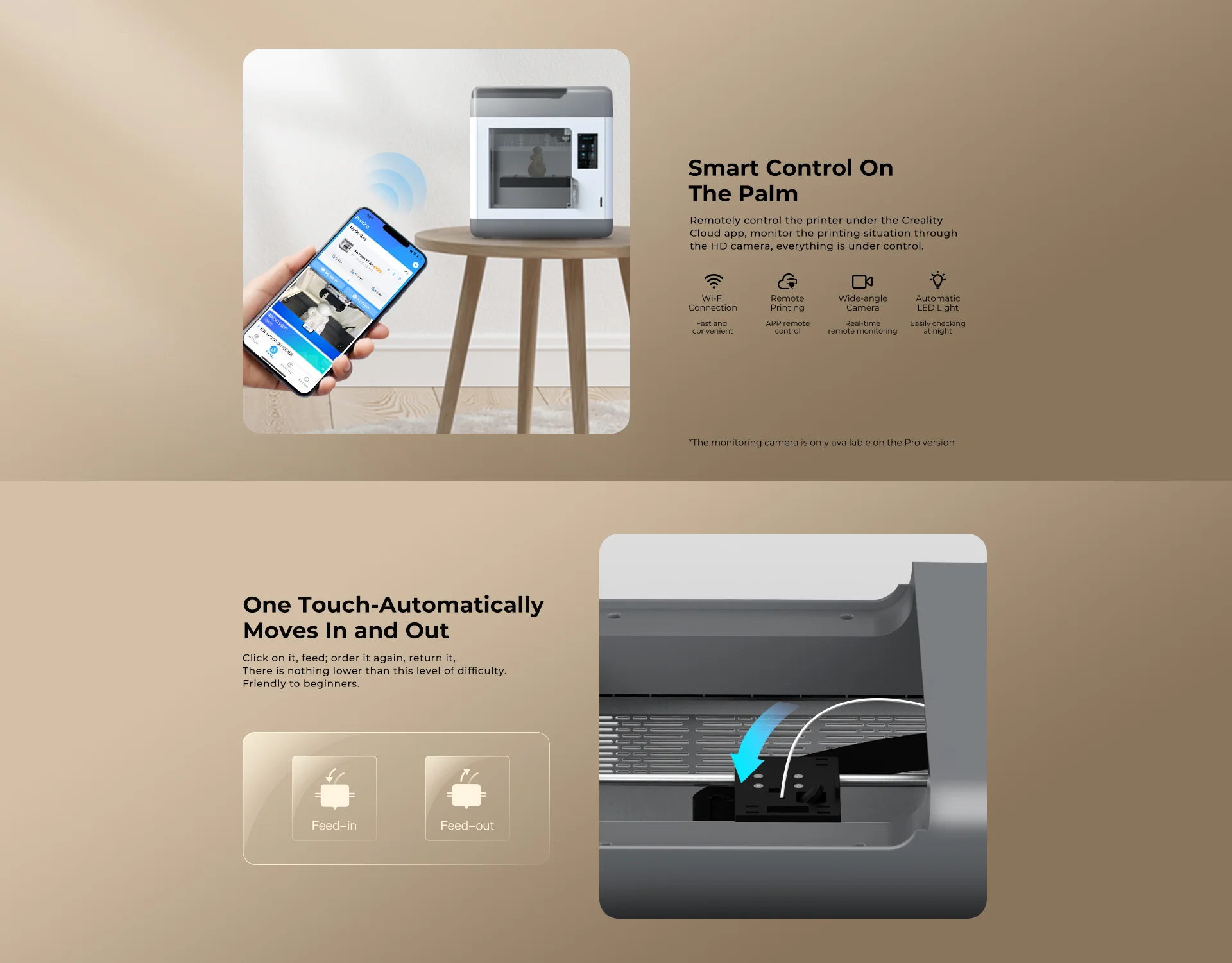
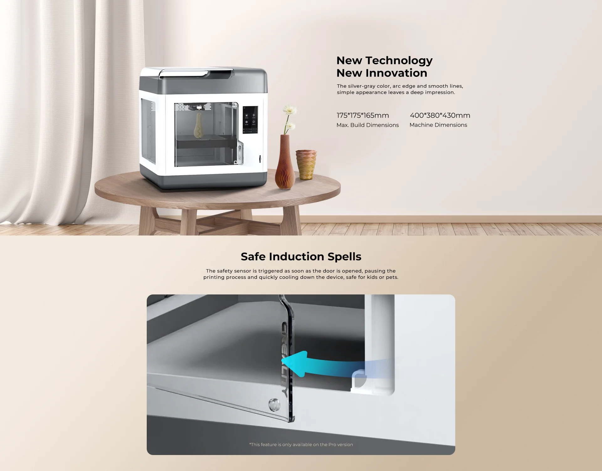
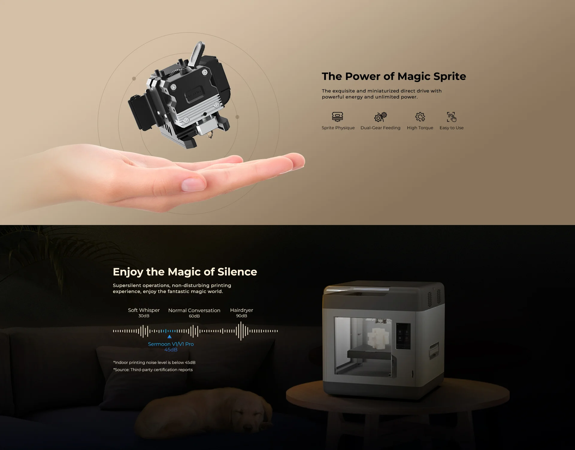
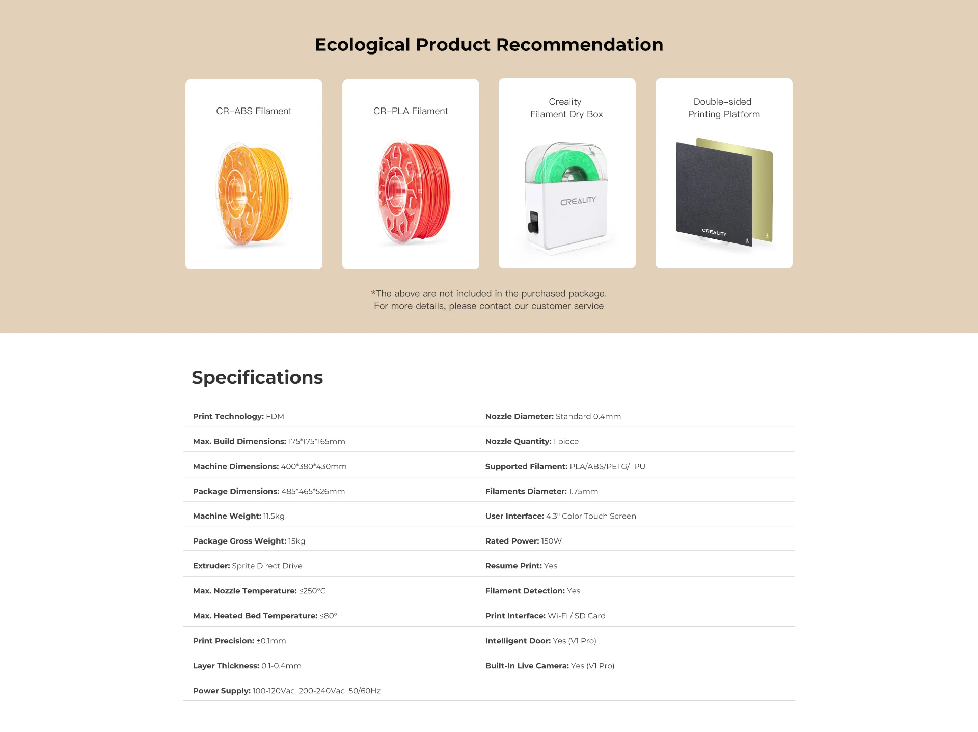
The Sermoon V1 Pro combines Creality's self-developed features in a sturdy, fully enclosed design. Equipped with the Sprite Direct Drive Extruder and Flexible PEI Magnetic Spring Steel Sheet, it offers enhanced printing capabilities. This ready-assembled printer features an intuitive touchscreen interface and auto-leveling option for easy setup. With a focus on PLA filament printing and a full enclosure enabling ABS filament use, the Sermoon V1 Pro stands out with its clever design tricks and safety features. Perfect for classrooms, it delivers great print quality, user convenience, and a streamlined experience.
What's in the box?
1 x Creality Sermoon V1 Pro
Resources
Support docs including manuals, firmware, slicing software etc..

The Volkano Constant series Mini UPS is a compact device that acts as a power bank for your WiFi during power outages. It has dual DC outputs for running two devices simultaneously and includes a USB charge port. With support for Power Over Ethernet (POE), it can power compatible devices with a single cable. The LED indicator shows the remaining power, and it automatically switches from AC to DC power during power failures. It comes with a dual DC power cable, mains cable, and a 1.8-meter DC power cable with a splitter. The Mini UPS offers electric leakage, overcharge, and overdischarge protection. It ensures uninterrupted WiFi connectivity, making it essential for homes and offices.
Features
- Up to 4 hours of power
- 8800 MAH high power batteries
- Suitable for wired or wireless networks
- Suitable for CCTV systems
- Dual DC output for 2 devices
- USB port for third device
- LED power indicator
- Power Over Ethernet
Specifications
- Input: 110 ~ 240VAC
- Output Port 1: DC 9V / 12V
- Output Port 2: DC 15V / 24V
- Output Port 3: USB DC 5V @ 2.5 Amp
- Output Port: 4 POE DC 15V / 19V / 24V
- Battery Capacity: 8800mAh
- Typical Runtime: 3 Hours (Fibre Terminal + Router)
- Total Output Power: 17 Watt
What's in the box?
1 x Volkano Constant series Mini UPS

What's in the box?
1 x Creality WIFI Cloud Box 2.0 With TF Card

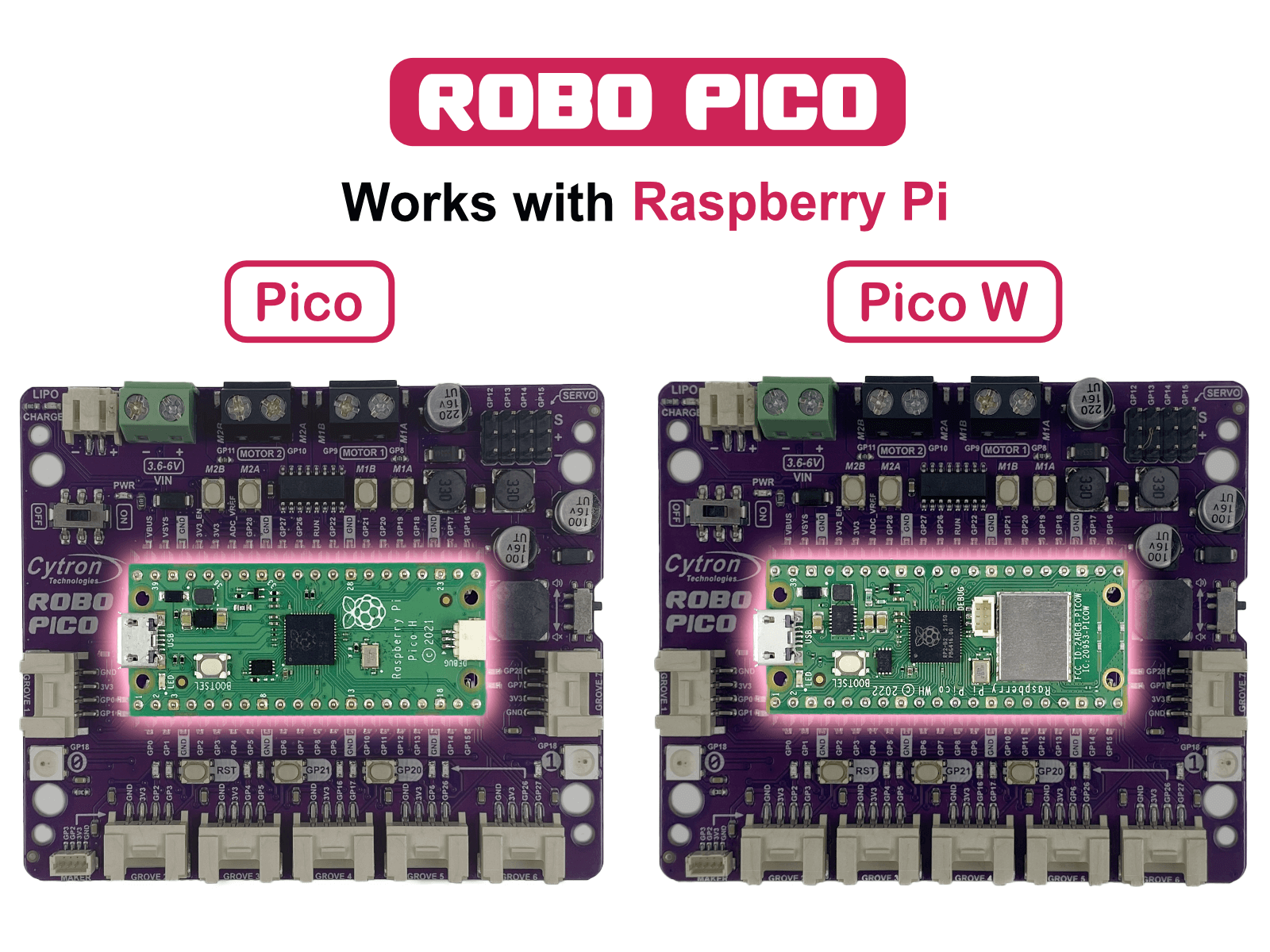
Your new best friend in crafting imaginative projects. Designed to integrate effortlessly with the Raspberry Pi Pico and Pico W, it’s equipped with a 2-channel DC motor driver, 4 servo motor ports, and 7 Grove I/O connectors. Whether you're designing a WiFi-controlled robot car or building a smart IoT project system, Robo Pico is here to make it an enjoyable journey.
Works with Raspberry Pi Pico and Pico WThe Robo Pico doesn't just use any controller - it leverages the power of the Raspberry Pi Pico and Pico W. The Raspberry Pi Foundation's robust controllers are ready to take your projects to the next level. Whether you're an experienced maker or a curious beginner, you'll appreciate the versatility they offer.
Unleash Your Creative Potential with Exciting Features
The Robo Pico goes beyond being just a board; it becomes a blank canvas for your imaginative masterpieces. With its dual-channel DC motor driver, 4 servo motor ports, 7 Grove ports, a Maker port, two RGB LED NeoPixels, and a piezo buzzer, it offers a limitless playground of possibilities. Picture the mesmerizing light spectacles you can craft, the precise motions you can orchestrate, the distinct sounds you can generate, and the groundbreaking Internet of Things (IoT) projects you can bring to life!
Connections Made Simple
No more stumbling around with tricky wiring or setups. Connections are simple with Robo Pico. All GPIO pins are thoughtfully arranged at the edge through the Grove and Maker ports, which skips the need for soldering and enables quicker connection of any Qwiic, STEMMA QT, or Grove I2C device. Meanwhile, all Raspberry Pi Pico or Pico W pins can be accessed via two 20-way pin headers. With Robo Pico, you only need to press a single button to reset the microcontroller, eliminating the hassle of plugging and unplugging the USB cable repeatedly.
Power Up The Way You Like
There are three ways to supply power to the Robo Pico - via the Raspberry Pi Pico / Pico W USB (5V) socket, with a single-cell LiPo/Li-Ion battery, or through the VIN (3.6–6V) terminals. However, only one power source is needed to power up both controller board and motors at a time. The power supply from all these power sources can all be controlled with the power on/off switch onboard.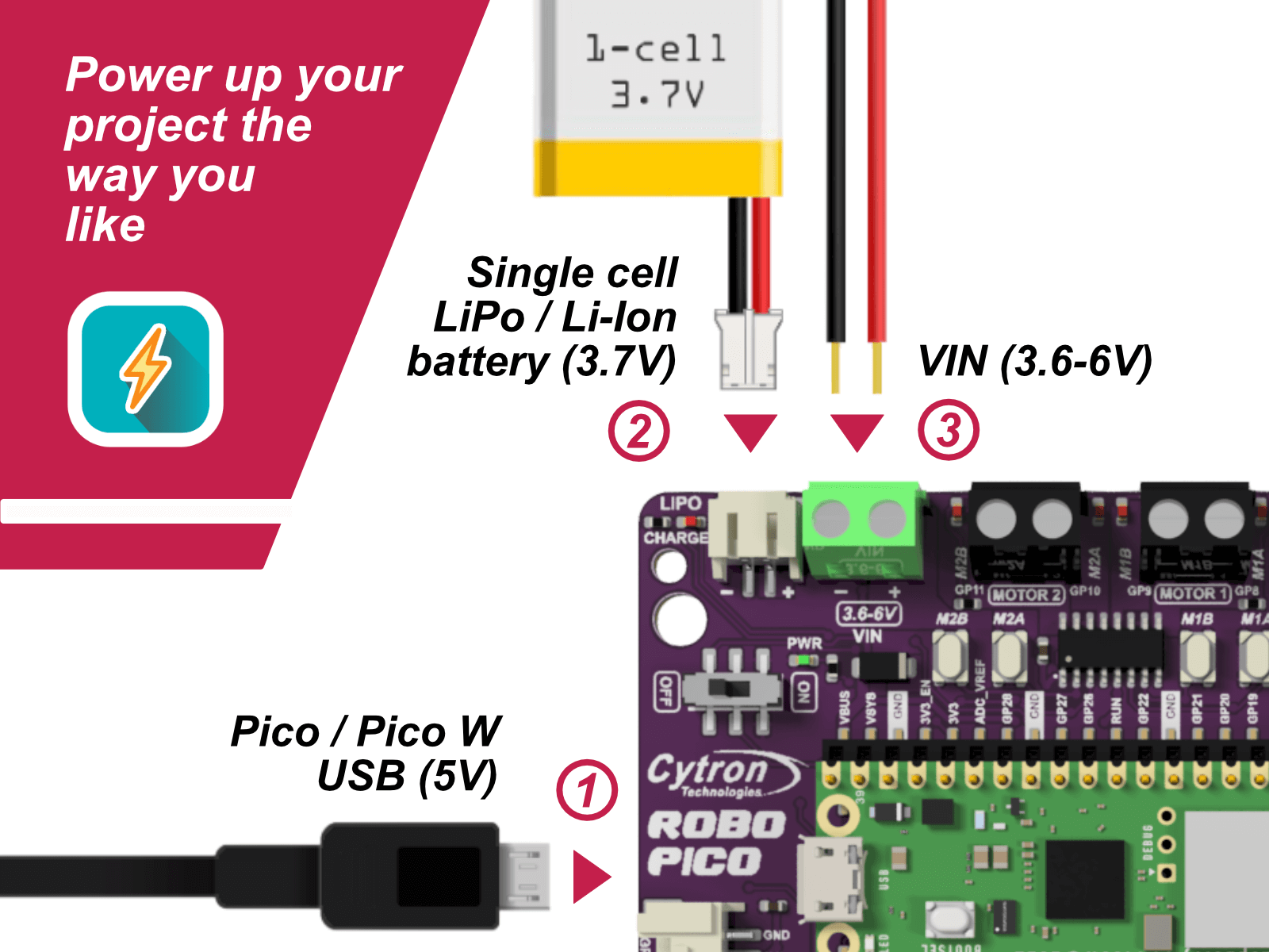
What's on the Board?
|
|
What's in the box?
1 x Robo Pico: Simplifying Robotics for Raspberry Pi Pico / Pico W (not included)
You can add a Pico WH to your order here
- Robo Pico Datasheet
- Robo Pico Getting Started Guide using CircuitPython (Cytron Tutorial Site)
- Robo Pico Getting Started Guide using CircuitPython (Github)
- 3D CAD
- Official Raspberry Pi Pico Page
- Getting started with Raspberry Pi Pico
- Raspberry Pi Pico Datasheet (pdf)
- Raspberry Pi Pico W Datasheet (pdf)
- Raspberry Pi Pico Python SDK
- Raspberry Pi Pico C/C++ SDK

With the Volkano X Allcast, you can Cast and Stream from any Phone or Laptop to a TV, Monitor, or a Projector.
Extend your computer display, or drag windows from your PC or MAC to your big screen for meetings, entertainment, or even just for an extra display.
Features
- Works with Android, Apple iOS, Windows, or Mac
- Transmit Video and Audio to a TV, Monitor or a Projector
- Supports Miracast, DLNA & Airplay
- USB Powered
- Up to 1080P Full HD
- Easily stream your favorite apps like Netflix and YouTube.
System Requirements
- Android Phone or Tablet: Android 4.2 Up
- Apple Phone or Tablet: iOS 7 Up
- Windows: 8.1, 10 & Up
- MAC: MAC OS 10.8 Up
- TV, Monitor, or a Projector with HDMI Input
- Requires an External USB Power Source
Specifications
- Video Resolution: Up to 1080P @ 60Hz
- Audio Channels: Up to 5.1 Surround Sound
- Chipset: RK3036 Dual Core Cortex A7, 1.2GHz
- Output: HDMI<br> Power: Micro USB 5 V @ 1 A
What's in the box?
1 x VolkanoX Allcast HDMI Wireless Display Receiver
1 x USB Power Cable
1 x Extension WiFi Receiver
1 x Instruction Manual

What's in the box?
1 x Type C to Type C power/data cable

Features
- Mounting holes for Arduino Uno R3/R4.
- Size: 145mm x 95mm.
- Ideal for use with Solderless 400 Point Breadboard (included).
- Acrylic board designed and laser cut inhouse.
- Shadow engraved on board for easy breadboard placing.
- Create an easy to use prototyping station
- Different lengths of male to male jumpers
What's in the box?
1 x Acrylic plate
4 x M2.5 + 5 standoffs
4 x M2.5x6 screws
4 x M2.5 nuts
4 x bumper pads
1 x 400 point breadboard
1 x set of 65 male jumpers

Visit our blog to get more info on what you can do with your Pico
This is a Raspberry Pi Pico Basic Kit by Cytron for the very first MCU launched by Raspberry Pi Foundation. The kit includes almost everything you need to kickstart your way in digital making and start learning MicroPython with Raspberry Pi Pico !
Specifications
This kit comes with Raspberry Pi Pico W with presoldered header.
What's in the box ?
1 x Breadboard 16.5x5.5cm (830 Holes)
1 x Buzzer-PCB Mount
1 x Finger Adjust Preset Potentiometer 10K
2 x LED 5mm Red
2 x LED 5mm Green
2 x LED 5mm Yellow
2 x LED Super Bright 5mm Blue
2 x PIR Sensor
3 x 6x6x1 Push Button 4Pin
5 x Resistor 0.25W 5% (330R)
10 x Male to Female Jumper Wire
20 x Male to Male Jumper Wire
1 x RPi W Pico WH (with presoldered header)
1 x Official 5V 2.5A USB micro B Power Supply ( to power your deployed project)
1 x Red Official USB Micro B cable (to connect and program your Pico from your PC or Raspberry Pi)
Resources
- Getting Started with Raspberry Pi Pico (pdf), C/C Development with the Pico and other RP2040-based microcontroller boards.
- Raspberry Pi Pico Datasheet (pdf), An RP2040-based microcontroller board
- Pico Python SDK (pdf), A MicroPython Environment for the RP2040 Microcontroller
- Pico C/C SDK (pdf), Libraries and Tools for C/C Development on the RP2040 Microcontroller
- RP2040 Datasheet (pdf), A microcontroller by Raspberry Pi
Check out some of the video tutorials that you can learn using this kit:
Traffic Light Controller with Raspberry Pi Pico
Reaction Game using Raspberry Pi Pico
Burglar alarm using Raspberry Pi Pico
Control LED using PWM on Raspberry Pi Pico

Specifications
- Wheel diameter: 24mm
- Wheel height: 13mm
- Screw holes x 4: M4
- Mounting Height: 35mm
- Mount type: Swivel plate
What's in the box?
1 x castor wheel black