
Kitronik


This is the perfect cable choice for those that want to output music or general sound for the BBC micro:bit, to either headphones or speakers.
At one end of the cable are the black and red crocodile clips, which connect to the microbits GND and Pin 0 respectively. At the other end of the cable is a 3.5mm TRS (tip, ring sleeve) stereo jack.
The 3.5mm TRS stereo jack means you can either connect your headphones directly to your BBC micro:bit or if you would rather use a speaker, you can use one of our MP3 mono amplifier kits to drive the speaker.
Please Note:
Although the BBC micro:bit can supply enough current to drive a pair of headphones, you will need an amplifier if you wish to drive an audio speaker. A MP3 mono amplifier kit is an ideal choice as it offers both the amplifier and speaker.
Please be aware however this lead does not work with true Mono leads and is designed to work with Stereo Leads.
Features
- Plug headphones directly onto the 3.5mm TRS stereo jack.
- Crocodile clips for direct connection to the BBC micro:bit.
Dimensions
- Length: 400mm.
- Clips: 28mm.
What's in the box?
1 x BBC micro:bit Audio Cable.
This pre-built Edge Connector Breakout Board for the micro:bit gives access to all the important pins on the bottom edge of the micro:bit.
Looking to do more with your micro:bit? Unlock its potential with this pre-built version of our Edge Connector Breakout Board! This breakout board has been designed to offer an easy way to connect additional circuits and hardware to the pins on the edge of the micro:bit. It provides access to all of the micro:bit processor pins allowing a lot of extra functionality to be added. The datasheet (below) includes a helpful diagram explaining the function of every pin on the micro:bit.
This Edge Connector Breakout Board for the micro:bit gives access to all of the important pins on the bottom edge of the micro:bit. 21 pins are broken out in total; providing additional I/O lines, direct access to buttons A and B, the LED matrix outputs and the I2C bus. Please refer to the datasheet below for more details.
The micro:bit pins are broken out to a row of pin headers. These provide an easy way of connecting circuits using jumper wires. The SCL and SDA pins are separated at the edge of the board (solder pads) providing easy identification. The PCB includes a prototyping area with 3V, 0V and unconnected rows that can be soldered to. This allows the easy connection of switches, sensors and any pull-up or pull-down resistors etc. as required.
To use the breakout board the micro:bit should be inserted firmly into the connector as shown below: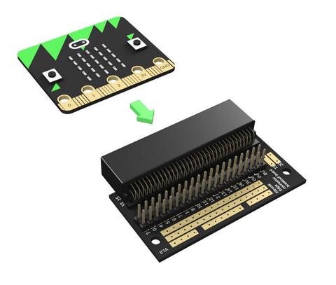
Note:
- This product is supplied with straight double row PCB pin headers already soldered to the breakout board
Features:
- Features a dedicated pin strip for quick and easy prototyping
- Breaks out 21 pins from the edge of the micro:bit
- Dedicated prototyping area with 3V and 0V rows
- Labelled pins and clear, straightforward documentation
Contents:
- 1 x Edge Connector Breakout Board for the micro:bit, pre-built
Dimensions:
- Length: 60mm
- Width: 40mm
- Height: 11.8mm
Video available at https://youtu.be/bzm4zepbGAc
Requires:
- 1 x micro:bit
Resources:

Our learn to solder pack is the ideal low cost solution for teaching soldering in the classroom/after school club. The pack provides all of the parts and PCB's required for a class size of 25 and also includes a 9V battery for testing purposes. Each pack comprises; 25 x PCBs, 100 x 100 ohm resistors, 25 x LED's, and a 9V PP3 battery.
We have also produced a step by step guide to soldering, which covers; equipment, solder, tinning & cleaning, soldering in 8 steps, de-soldering in five steps, wire preparation, examples of good and bad solder joints, basic PCB repair, resistor information, LED information, full step by step build information for the kit, and how the learn to solder kit works. This guide covers everything that you might need to discuss with students and can form the basis of your lesson plan.
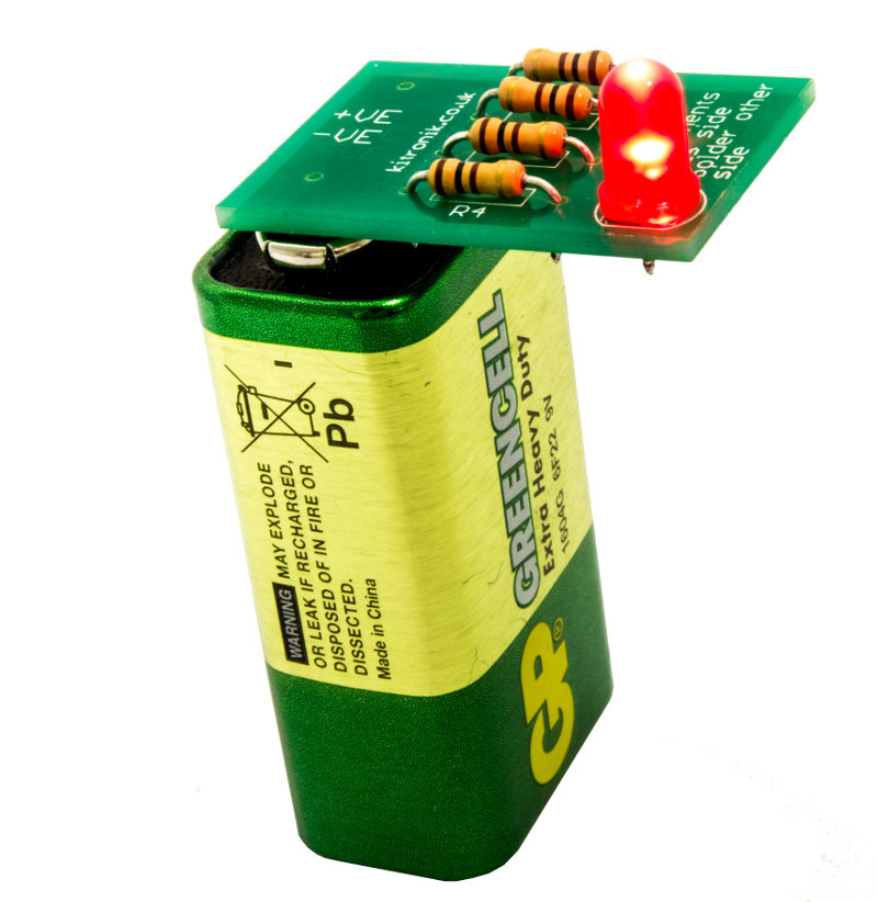
Using the kits and the step by step guide, each student will solder four resistors and one LED to their PCB before pressing it to the terminals of the 9V battery to check that their board works. Using the guides they will be able to examine their own work and troubleshoot problems. The battery pads on the PCBs have been shaped inline with the battery terminals on a PP3 battery making it straightforward to see which way around it should be placed on the battery.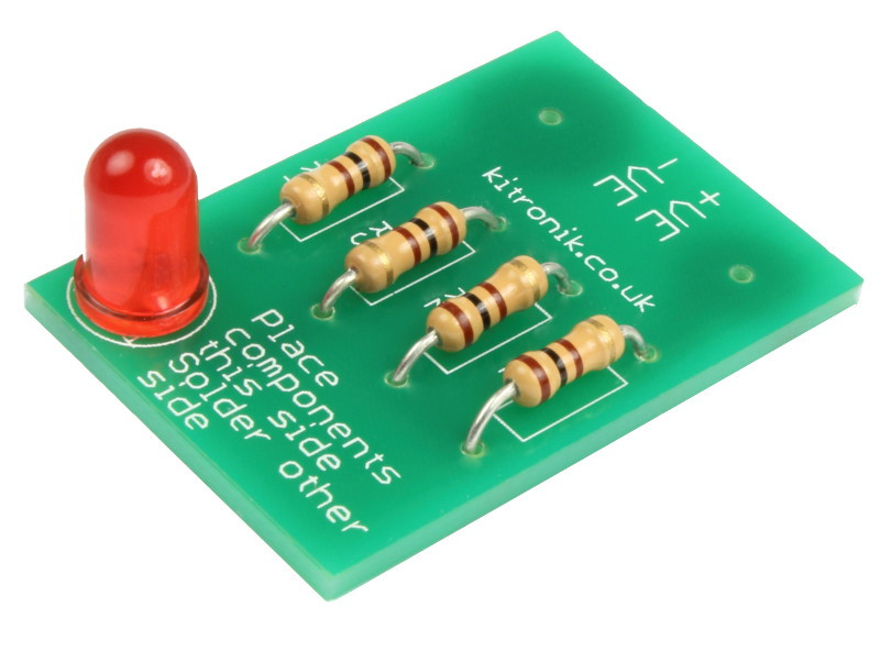
Features
- Purpose built PCBs that can be tested, once built, with the supplied 9V PP3 battery.
- Low cost classroom pack for 25 students.
- Easy build kit.
- Full teaching resources and step by step guides available for this kit below.
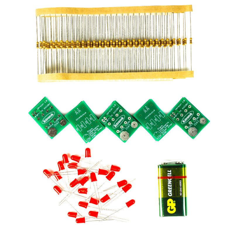
What's in the box?
100 x 100 ohm Resistors.
25 x Red 5mm Diffused LED - 275mCd.
25 x Learn To Solder PCBs.
1 x 9V Zinc Chloride PP3 Battery.
Dimensions
- Built Height: 11mm.
- PCB Length: 31mm.
- PCB Width: 21mm.
- PCB Height: 1.5mm.

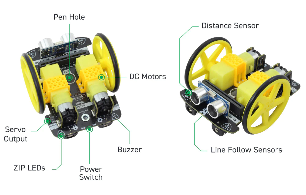
Develop your coding skills with the Kitronik :MOVE Motor for micro:bit, a fun introduction to buggies and robotics.
The Kitronik :MOVE Motor for the BBC micro:bit provides a fun introduction to buggy robotics. More than just a programmable buggy, learning to use all of the included features will give the budding roboteer a solid grounding in robotics as a whole.
Learn about movement, how to utilise light and sound, obstacle detection and avoidance, and how to code :MOVE Motor to follow a line. When used in conjunction with the micro:bit's radio features, the possibilities are endless.
Attached to the chassis are two bi-directional DC motors with variable speed control. The wheels have rubber tyres and are a simple push-fit onto the motor shafts. Slot a BBC micro:bit into the edge connector and you are ready to code. There is no other assembly required and no tools required.
There are built-in battery holders for 4x AA batteries. This provides a regulated voltage supply to power the BBC micro:bit which is fed into the edge connector. There is also a power switch to conserve batteries when the buggy is not in use.
The micro:bit slots into the onboard edge connector. Code the micro:bit, plug it into the buggy, switch the power on, and then play.
CODE IT !
:MOVE Motor can be coded using the Microsoft MakeCode editor. Kitronik has produced a set of custom MakeCode blocks to simplify coding the completed buggy. The booklet that comes with the buggy contains more detailed instructions on using the blocks and writing code. If you are feeling more adventurous or relish a challenge, :MOVE Motor can also be coded with Python.
Also within the booklet (that comes inside the box), are some quick tutorials to get you started. There are also additional online tutorials and step by step guides for extra projects.
Note:
- This kit does not include a micro:bit, a micro:bit can be obtained from here.
- No soldering is required!
- Minimal assembly required.
Specifications
| Length | 110mm. |
| Width | 90mm. |
| Voltage | Nominal 4.8 - 6V (4xAA batteries). |
| Motors | Pins 19 and 20 (via I2C). |
| Audio Buzzer | Pin 0 (Standard Music Pin). |
| Visual (4x ZIP LEDs) | Pin 8. |
| Line Follow (IR) | Pins 1 (Right) and 2 (Left). |
| Ultrasonic | Pins 13 (Trigger) and 14 (Echo). |
| Servo Connections | 2 on Pins 15 & 16. |
Features
- The Kitronik :MOVE Motor for the BBC micro:bit provides a fun introduction to buggy robotics and coding.
- It is backed up by a range of fun tutorials to introduce you to all of the great features.
- All of the tutorials and resources are free.
- There is no soldering required and assembly is quick and super simple.
- The buggy features two bi-direction DC motors.
- There are ultrasonic distance and line following sensors onboard.
- It also features a Piezo sounder and pen mount.
- There are 4 full-colour programable ZIP LEDs.
- Two pin outputs that are ideal for servo connections (can be used for other inputs and outputs).
- The battery holder is built onto the chassis.
- The buggy is also fitted with a power switch to conserve the batteries.
- There is also an onboard edge connector for the micro:bit, code, plug and play.
- Kitronik has produced custom MakeCode blocks to simplify coding with the MakeCode editor.
- You can also optionally add a pen for drawing or a robot claw
What's in the box?
1 x :MOVE Motor chassis.
2 x Wheel and tyres.
1 x Booklet
You will also need....
1 x micro:bit
4 x AA batteries
1 x micro USB cable(to program the :MOVE)
Resources

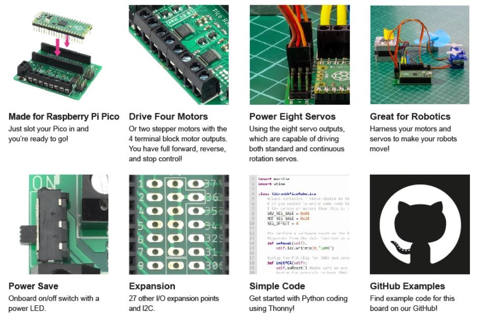
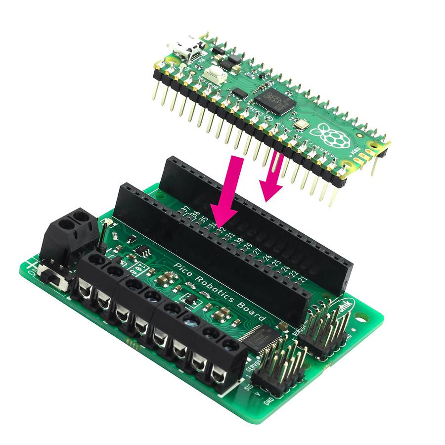
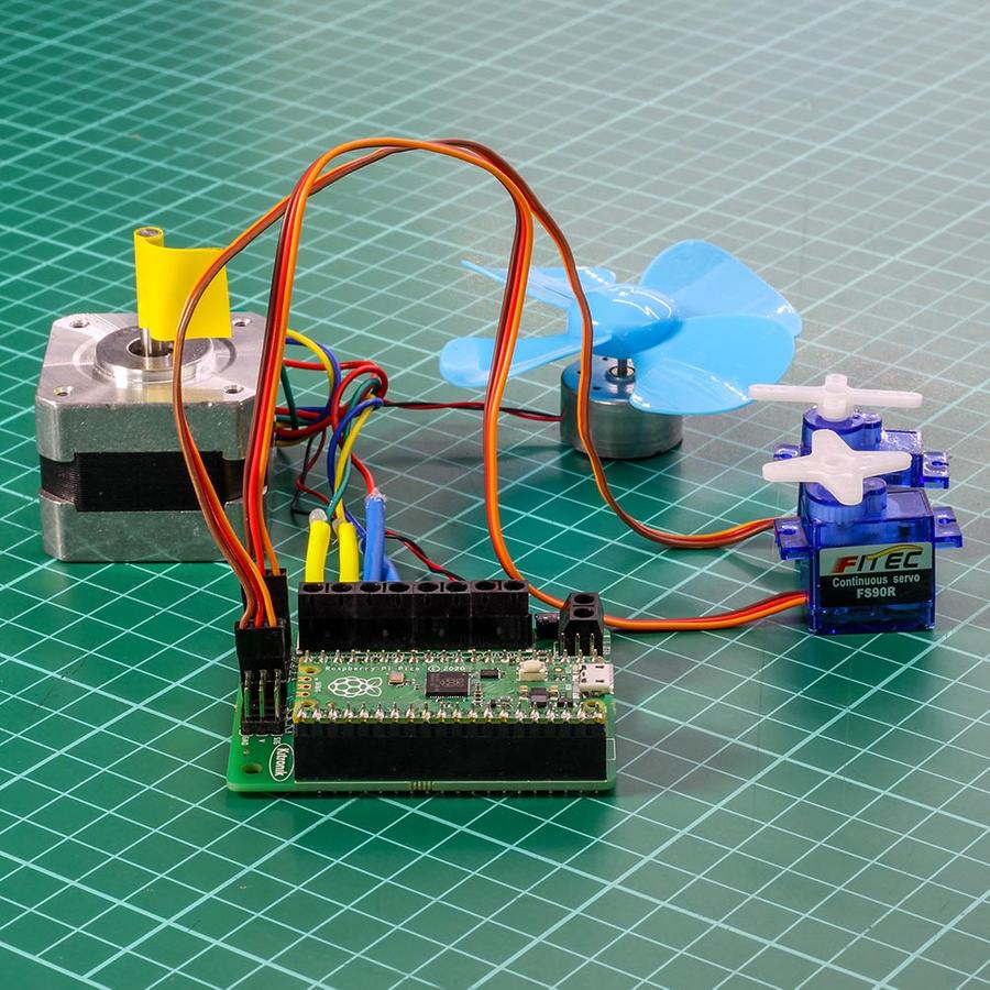
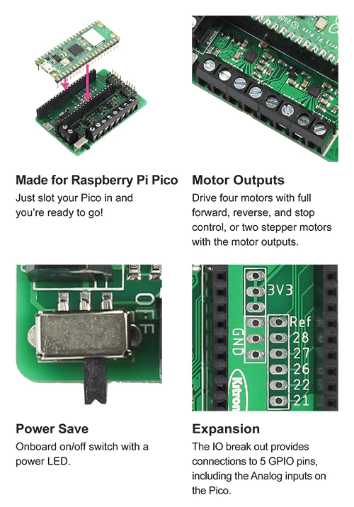
Make the Raspberry Pi Pico the core of your new robotics project with the Kitronik Compact Robotics Board for Raspberry Pi Pico.
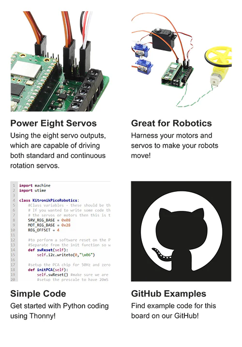
The Robotics Board features 2 Dual H Bridge Motor Driver ICs. These are capable of driving 2 standard motors or 1 stepper motor each, with full forward, reverse, and stop control. There are also 8 servo outputs, capable of driving standard and continuous rotation servos. They can all be controlled by the Pico using the I2C protocol, via a 16 channel driver IC. The IO break out provides connections to all the unused pins on the Pico. The 27 available I/O pins allow other devices, such as sensors or ZIP LEDs, to be added to the board.
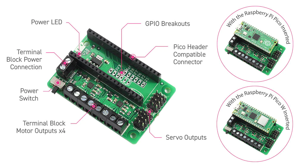
Power is provided via either a terminal block or servo style connector. The supply is then controlled by an on/off power switch to the board and there is also a green LED to indicate when the board has power. The board then produces a regulated 3.3V supply which is fed into the 3V and GND connections to power the connected Pico. This removes the need to power the Pico separately. The 3V and GND pins are also broken out on the header, which means external devices can also be powered.
To use the robotics board, the Pico should be firmly inserted into the dual row pin socket on the board. Ensure the Pico is inserted with the USB connector at the same end as the power connectors on the robotics board. This will allow access to all of the board functions and each pin broken out.
Features :
- A compact yet feature-packed board designed to sit at the heart of your Raspberry Pi Pico robotics projects.
- The board can drive 4 motors (or 2 stepper motors), with full forward, reverse, and stop control, and 8 servos.
- It also features 27 other I/O expansion points and Power and Ground connections.
- The I2C communication lines are also broken out allowing other I2C compatible devices to be controlled.
- Additionally, the board features an on/off switch and power status LED.
- Power the board via either a terminal block or servo style connector.
- The 3V and GND pins are broken out to solder pads, allowing external devices to be powered.
- Code it with MicroPython via an editor such as the Thonny editor.
Specifications :
| 3 - 10.8V |
| 8 |
| 4 DC / 2 Stepper |
| Same as Supply Voltage |
| 12 Amps |
| 1.5A / Motor |
| 26 (via solder pads) |
| 8 (via solder pads) |
| 7 (via solder pads) |
What's in the box ?
1 x Kitronik Robotics Board (for Raspberry Pi Pico)
(* Raspberry Pi And add ons are NOT included - ONLY the Robotics Board *)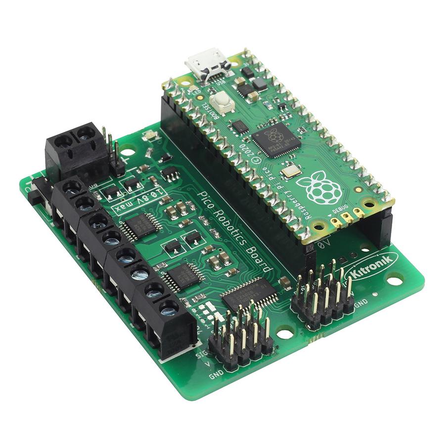
(* Raspberry Pi And add ons are NOT included - ONLY the Robotics Board *)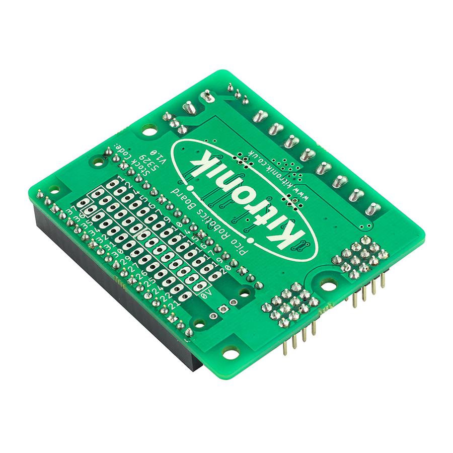
(* Raspberry Pi And add ons are NOT included - ONLY the Robotics Board *)

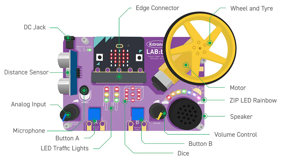
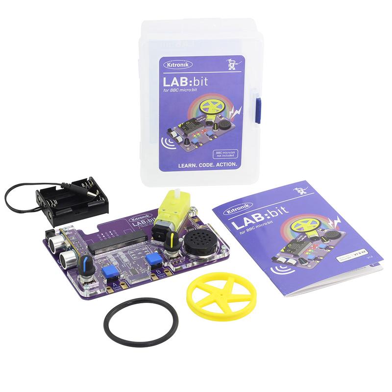
The Kitronik LAB:bit for the BBC micro:bit offers a super fun way for children to learn about coding in an engaging and hands-on way. It has been specifically designed for the classroom for KS2 computing and is backed by online MakeCode tutorials, simplified custom blocks, and a detailed getting started guide. Supplied in the box are; a battery holder (3 x AA), a wheel and tyre for the motor, and the detailed easy to follow guide.
The board is absolutely packed with an impressive array of features and devices for easy delivery of fun and informative lessons. These include; a motor, ultrasonic distance sensor, 2 x large user-assignable tactile buttons (with indicator LEDs), a microphone, speaker (with volume control), 7 programmable ZIP LEDs(in an arc), A user-assignable potentiometer control, 2 x sets of traffic light LEDs, and LEDs arranged in a dice formation (that can also be used for displaying digits).
The board also features; an edge connector for the micro:bit to slot into, a pre-fitted protective acrylic cover, clip-able pads for attaching an additional motor, 2 x clip-able pads for attaching further buttons/switches, Colour changing power indication LEDS, a cutaway for easy reset button access, and pre-fitted anti-slip rubber feet.
This all in one laboratory environment ships with a detailed getting started guide, filled with step by step information that can easily be followed by either teacher or pupil. The guide starts with an introduction to using a micro:bit and the MakeCode editor, with each explained in detail. This is then followed by instructions for fitting the wheel to the motor. Each area of the board is explained in detail, complete with code examples for each. As with the previous sections, this part of the booklet has been designed so that it can be used by teachers and pupils.
Coding is done via the MakeCode blocks editor. Kitronik has produced custom blocks for the editor to ensure that they are suitable for use with pupils aged 7-10. Each area of the board has its own blocks that all slot together in intuitive ways and they have been organised into subdirectories by type. For example, all of the blocks for the motor are in one submenu and blocks for the traffic lights are in another submenu. There is also an 'other' submenu that contains blocks for the more advanced/older students who require an extra level of challenge. Detailed information on how to add these blocks to MakeCode can be found in the Getting start guide that ships with LAB:bit.
Power is provided via the provided 3 x AA battery holder into the DC barrel jack input. The board has been rated for a maximum of 6V and a minimum of 3V, 3V - 4.5V recommended. The onboard power regulation circuit provides power to the board and to the micro:bit, removing the need to power the micro:bit separately. LAB:bit has an inbuilt polarity protection circuit for the DC input. There is a Colour changing power LED to indicate when the battery voltage is getting low.
- No soldering.
- Minimal mechanical assembly required. The wheel needs to have the tyre fitted and then to be fitted to the onboard motor.
- This kit is not supplied with a micro:bit. The micro:bit is available separately here.
Features:
- LAB:bit is an all in one educational platform designed for the delivery of KS2 computing in the classroom (7 - 10-year-olds).
- It's packed full of devices, LEDs, switches, sensors, and other programmable features.
- It features an edge connector for the micro:bit to slot into, no tools required.
- LAB:bit is supplied with a pre-fitted protective acrylic cover.
- Additionally, there are clip-able pads for attaching an additional motor, 2 x clip-able pads for attaching further buttons/switches, colour changing power indication LEDs, and a cutaway for easy reset button access.
- There are also pre-fitted anti-slip rubber feet to ensure that LAB:bit stays securely on the desk.
- Code it with blocks in the MakeCode editor.
- Kitronik custom blocks to make coding more intuitive and straightforward.
- Custom blocks are grouped by type to make it easy to go straight to the blocks you need.
- No soldering!
- Minimal mechanical assembly required.
- Supplied in the box are; a battery holder (3 x AA) and a wheel and tyre for the motor.
- Power LAB:bit via the provided 3 x AA battery holder.
- The board is rated for 3V - 6V.
- It has an inbuilt polarity protection circuit for the DC input.
- The onboard power regulation circuit provides power to the board and to the micro:bit, removing the need to power the micro:bit separately.
- LAB:bit is supplied with a fully comprehensive getting started guide. It takes you through everything you need to know and can be followed by both teacher and pupils.
What's in the box ?
1 x Kitronik LAB:bit for the BBC micro:bit
1 x Yellow 5 spoke injection moulded wheel and rubber tyre.
1 x 3AA battery holder.
(* Micro:bit NOT Included *)
Requires the following :
- micro:bit
- USB cable for connecting the micro:bit to a computer.
- 3 x AA Batteries.
- Optional - 5V USB Power Supply (1A or more).
- 7 online MakeCode experiments that teach you how to create code for each area of the board, they are.
- A Pirate ship for LAB:bit.
- Tech Talks - live stream playback.
- Insight Resources Mr Bit:
- LAB:bit downloads.
- Tutorial 1: https://youtu.be/3OMRCZJM5pc
- Tutorial 2: https://youtu.be/xndCctCDCdQ
- Tutorial 3: https://youtu.be/WyJ5bMPAGfg
- Tutorial 4: https://youtu.be/E7jYcPik43Y
- Tutorial 5: https://youtu.be/5pPr_XRS1cE
- Tutorial 6: https://youtu.be/5BDvlVw3M44
- Tutorial 7: https://youtu.be/6v39f_EWGcs
- Projects: https://youtu.be/fQBEHESlxQc
- Download Mr Bit,
(* Micro:bit NOT Included *)
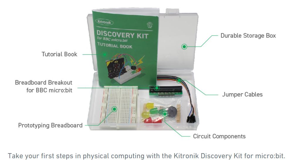
The Kitronik Discovery Kit for BBC microhttps://www.pishop.co.za/store/microbitbit is a great way to get started with both programming and electronics. The Kit contains five experiments that start very simply, building up to simulating real world systems as confidence grows.
The included booklet assumes no prior knowledge and contains detailed information about everything the new user will need to know. It covers everything from using a prototyping board to how to use the Microsoft MakeCode Editor, and everything in between. This is the ideal kit for someone who is new to the micro:bit, electronics, and coding.
The kit contains five experiments and all of the components required to complete them. Each experiment has; a complete code walk-through, a circuit diagram and a top-down breadboard view, full explanations of what is happening, and how the electronics work.
Notes
- This kit does not include a micro:bit, a micro:bit can be obtained from here.
- No soldering is required and you can build your first circuit in minutes!
Features
- This kit offers a great introduction to both coding and electronics.
- No soldering required - build your first circuit in minutes!
- Make the 5 experiments in the step-by-step tutorial book and learn as you go.
- All parts are included to conduct the 5 experiments.
- Once you have completed all of the included experiments, you have the perfect prototyping system for further adventures with the micro:bit.
- The code can be created in Microsoft's easy to use MakeCode editor.
What's in the Box?
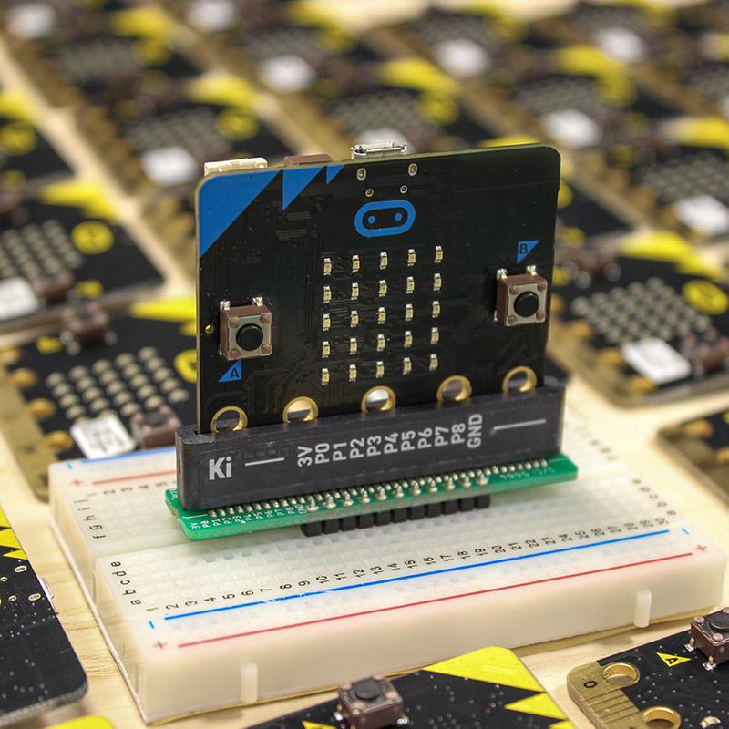
1 x Breadboard breakout for the BBC micro:bit.
1 x Small Prototype Breadboard.
2 x Red 10mm LED.
2 x Yellow 10mm LED.
2 x Green 10mm LED.
10 x 330Ω Resistor.
1 x Piezo Element Buzzer.
10 x Male to Male Jumper Wires.
You will also need a micro:bit GO or micro:bit Junior kit
The included experiments are;
- LED Control Circuit.
- Buzzer Jukebox.
- Lights in sequence.
- Digital LED Thermometer.
- Traffic light with pedestrian crossing.
Requires
- 1 x micro:bit
- 1 x USB Type-A to Micro-B USB.
Resources
Below you will find three links. We have produced the code for each of the experiments, for each of the additional challenges, and also Python versions of each of the experiments. Each of the downloads are zip files, which will need to be unzipped to access the code examples. We have included two versions for each python experiment, a HEX file and a PY file.
- All 5 Experiments MakeCode Code Examples.
- All 5 Challenges MakeCode Code Examples.
- All 5 Experiments Python Code Examples.
MakeCode Instructions
Connect the micro:bit to a spare USB port on your computer. The micro:bit will show up as a removable disk drive in File Explorer (Windows). Once unzipped, the individual MakeCode files can be dragged and dropped onto the micro:bit in File Explorer (Windows). An orange light will begin to flash on the rear side of the micro:bit, once the flashing stops the transfer is complete and the program can be run. Alternatively, the files can be dragged and dropped directly into the MakeCode editor.
Python Instructions
Connect the micro:bit to your computer in the same way as outlined above. The HEX versions can be dragged and dropped onto the micro:bit in the same was a MakeCode HEX files. Alternatively, the files can be dragged and dropped directly into the Python editor or a Python ready editor of your choice.
- For more handy guides, visit the Kitronik University micro:bit page.
Third-Party Resources
Insight Resources Mr Bit is an online educational coding platform that also features sections devoted to some of our key micro:bit accessories, including this kit. This content has been developed by Insight Resources and any questions relating to them should be directed at their contact information. To access these resources, please visit;
Related Resources

Kitronik Inventor's Kit for BBC micro:bit has been one of the most successful products we have launched. Having discovered a need for an ultimate beginner product, we also recently launched...

* micro:bit NOT Included *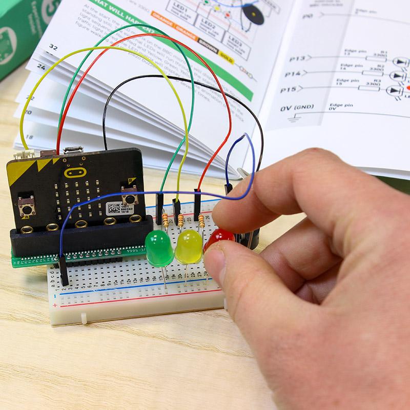
* micro:bit NOT Included *

The Kitronik Inventor's Kit for Arduino is a great way to get started with programming and hardware interaction with the Arduino in the classroom. This Inventor's Kit contains everything you need to complete 10 experiments including using LEDs, motors, light sensors and capacitors.
Arduino is an open-source code-able electronics platform, which has been designed for anyone making interactive projects. Arduino board can process inputs from many sensors, and also control outputs such as LEDs and motors.
The Arduino is controlled by the code with which it is programmed. This code is written in the Arduino programming language, using the Arduino development environment. Once complete the code is easily transferred to the Arduino board using a simple USB lead.
To get you off to a flying start, we have included an easy to follow tutorial book which guides you through creating the 10 experiments. You don't need any experience with programming as the tutorial book will guide you every step of the way. You'll be programming and creating circuits in no time!
Note:
- This kit requires assembly.
- No soldering is required and you can build your first circuit in minutes!
- This kit does not include an Arduino UNO.
- This kit is available as a single pack or as a pack of 20.
Features:
- No soldering required - build your first circuit in minutes!
- Make 10 experiments included in the provided step-by-step tutorial book.
- All parts are included to conduct the 10 experiments.
- Small Prototype Breadboard included for fast prototyping.
What's in the box?
1 x Mounting Plate.1 x 7 Segment Display.
1 x Servo.
1 x Potentiometer - Vertical Type (finger adjust) 100K.
1 x Finger Adjust Spindle.
4 x Plastic Spacer 10mm.
1 x Small Prototype Breadboard.
1 x Terminal Connector.
4 x Push Switch.
1 x Motor.
1 x Transistor.
2 x Red 5mm LED.
2 x Orange 5mm LED.
2 x Yellow 5mm LED.
2 x Green 5mm LED.
1 x RGB 5mm LED.
1 x Fan Blade.
5 x 2.2KΩ Resistor.
5 x 10KΩ Resistor.
10 x 220Ω Resistor.
20 x Male to Male Jumper Wires.
1 x 470uF Electrolytic Capacitor.
1 x Piezo Element Buzzer.
4 x Pan Head M3 Machine Screw.
1 x Phototransistor.
Video: https://youtu.be/aswor6BKXSY
Requires:
- An Arduino board such as The Arduino Uno, Compatible Uno, Maker Uno or Maker Uno Plus
- Phillips Screwdriver.
- Terminal Block Screwdriver.
- USB A to USB B Cable for Uno or the micro USB cable for Maker Uno and Maker Uno Plus
Inventors Kit Additional Online Resources:
- Tech Talks - live stream playback.

The Kitronik Inventor's Kit for the BBC micro:bit is a great way to get started with programming and hardware interaction with the BBC micro:bit. This Inventor's Kit contains everything you need to complete 10 experiments including using LEDs, motors, LDRs and capacitors.
To get you off to a flying start, we have included an easy to follow tutorial book which guides you through everything you will need to know about programming the BBC micro:bit. You don't need any experience with programming as the tutorial book will guide you every step of the way. You'll be programming and creating circuits in no time!
The Kitronik Inventor's Kit for the BBC micro:bit provides a fantastic way of learning how to construct and control electronic circuits. The BBC micro:bit has a selection of pins that are located on the bottom edge of its PCB. By using our specially designed Edge Connector Board for the BBC micro:bit in conjunction with the breadboard (see below), it is easy to use these pins to connect additional components to the BBC micro:bit.
Note
- This kit requires assembly.
- No soldering is required and you can build your first circuit in minutes!
- This kit does not include a BBC micro:bit.
- If you purchase a micro:bit separately you may also need to purchase a Battery Enclosure and a USB Cable, depending on which micro:bit option you purchase.
Features
- No soldering required - build your first circuit in minutes!
- Make 10 experiments included in the provided step-by-step tutorial book.
- All parts are included to conduct the 10 experiments (listed below).
- Breaks out 21 accessible pins from the BBC micro:bit using the Edge Connector Board for the BBC micro:bit (included).
- Small Prototype Breadboard included for fast prototyping.
- This kit is available as a single pack or as a 20 pack.
What's in the box?
The contents below are for a single Inventor's kit pack.
- 1 x Mounting Plate.
- 1 x Potentiometer - Vertical Type (finger adjust) 100K.
- 1 x Finger Adjust Spindle.
- 2 x Plastic Spacer 10mm.
- 1 x Sticky Fixer for Battery Pack.
- 1 x Small Prototype Breadboard.
- 1 x Terminal Connector.
- 4 x Push Switch.
- 1 x Motor.
- 1 x Transistor.
- 2 x Red 5mm LED.
- 2 x Orange 5mm LED.
- 2 x Yellow 5mm LED.
- 2 x Green 5mm LED.
- 1 x RGB 5mm LED.
- 1 x Fan Blade.
- 5 x 2.2KΩ Resistor.
- 5 x 10KΩ Resistor.
- 5 x 47Ω Resistor.
- 1 x Edge Connector Breakout Board for BBC micro:bit.
- 10 x Male to Male Jumper Wires.
- 10 x Male to Female Jumper Wires.
- 1 x 470uF Electrolytic Capacitor.
- 1 x Piezo Element Buzzer.
- 4 x Pan Head M3 Machine Screw.
- Depending on which booklet version your Inventors Kit shipped with, you will have one of the two following components;
- 1 x Miniature LDR. For booklet versions pre V1.7.
- 1 x Phototransistor. For booklet versions post V1.7.
Requires
All of the experiments included in this booklet (listed below) are based on the Microsoft MakeCode Editor. We have also produced a MicroPython code example for each of the experiments and Video resources featuring a walk-through and hints and tips to help you complete the experiments.
Inventors Kit Additional Free Resources
| Exp No#. | Experiment Name. | Resource Type. |
|---|---|---|
| 1 | Say Hello to the BBC micro:bit. | Further Help. |
| 2 Pre V1.7 | Using an LDR and analog inputs. | Full Experiment + Further Help. |
| 2 V1.7 | Using a Light Sensor & analog inputs. | Full Experiment + Further Help. |
| 3 | Dimming an LED using a potentiometer. | Further Help. |
| 4 | Using a transistor to drive a motor. | Full Experiment + Further Help. |
| 5 | Using the accelerometer to control motor speed. | Further Help. |
| 6 | Setting the tone with a piezo buzzer. | Further Help. |
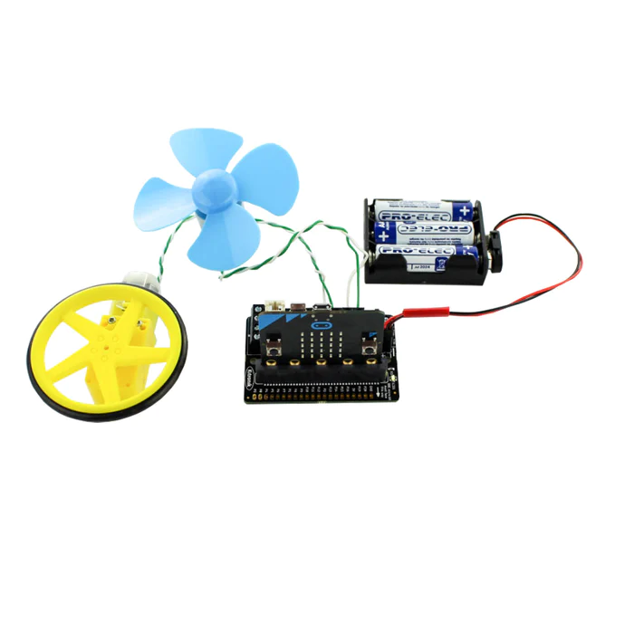
| 7 | Wind Power. | Full Experiment + Further Help. |
| 8 | Making a game using the compass. | Further Help. |
| 9 | Capacitor charge circuit. | Further Help. |
| 10 | Using an RGB LED. | Further Help. |
| 11 | Making a pedestrian crossing. | Full Experiment + Further Help. |
| 12 | Making a random dice. | Full Experiment + Further Help. |
Third-Party Resources
Insight Resources Mr Bit is an online educational coding platform that also features sections devoted to some of our key micro:bit accessories, including this kit. This content has been developed by Insight Resources and any questions relating to them should be directed at their contact information. To access these resources, please visit;

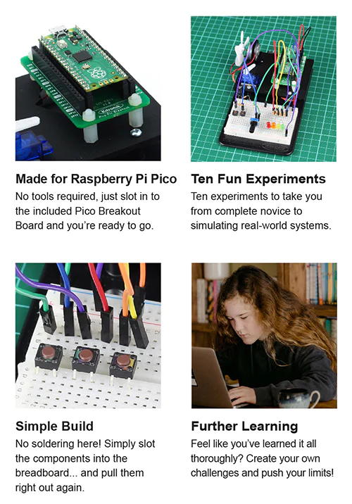
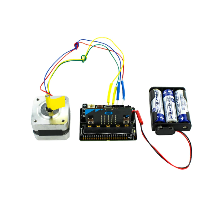
The Kitronik Inventor's Kit for the Raspberry Pi Pico provides a fantastic way of learning how to construct and control electronic circuits with the Pico and MicroPython.
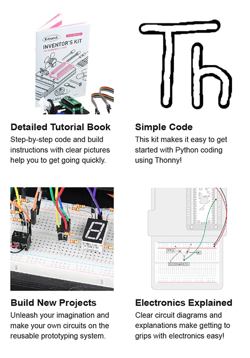
The Kitronik Inventor's Kit for the Raspberry Pi Pico offers the perfect introduction to physical computing with the Pico. This Inventor's Kit contains everything you need to complete 10 exciting experiments and the included booklet walks you through every step of each. Note: The Pico is not supplied with this kit, a pre-soldered one can be obtained separately here.
The possibilities for the kit are endless and the booklet is intended to get you off to a flying start. Before moving on to the experiments, it introduces you to the Raspberry Pi Pico and guides you in getting it ready for use. There is also an introduction to coding, how to run Python code on the Pico, guidance on using Breadboards, and also a detailed assembly guide for the kit.
Each experiment is then explained in full in a clear and concise manner. The full-colour booklet details the parts you need, the code used, a breadboard wiring diagram, a circuit diagram, and a full description of what is happening and why. The 10 experiments start simple and get more difficult as you progress through them.
Much like our Inventor's Kit for micro:bit and Inventors Kit for Arduino, this kit is built around our Inventor's prototyping system. It comprises an injection moulded base plate, onto which the breadboard is affixed, and the included laser cut plate is mounted. The laser-cut plate has mounting points for the included motor, servo, and Pinout board for Raspberry Pi Pico. There are also more than 60 components and connectors in the kit, such as; LEDs, switches, motors, transistors, resistors, and more! Please see the contents section below for a full list.
Note:
- Due to supply issues, initial orders of this inventors kit will be shipped in a brown box and not the green and white box.
- There is no soldering required for this kit.
- The kit does involve some mechanical assembly.
- The Pico is not supplied with this kit, a pre-soldered one can be obtained separately here.
Features:
- The Kitronik Inventor's Kit for the Raspberry Pi Pico provides a fantastic way of learning how to construct and control electronic circuits with the Pico and MicroPython.
- No soldering is required, build your first circuit in minutes.
- Work through the 10 included experiments, following the detailed full-colour guide booklet.
- The kit includes the Kitronik Inventors prototyping system, also found in the Inventor's Kit for micro:bit and Inventors Kit for Arduino.
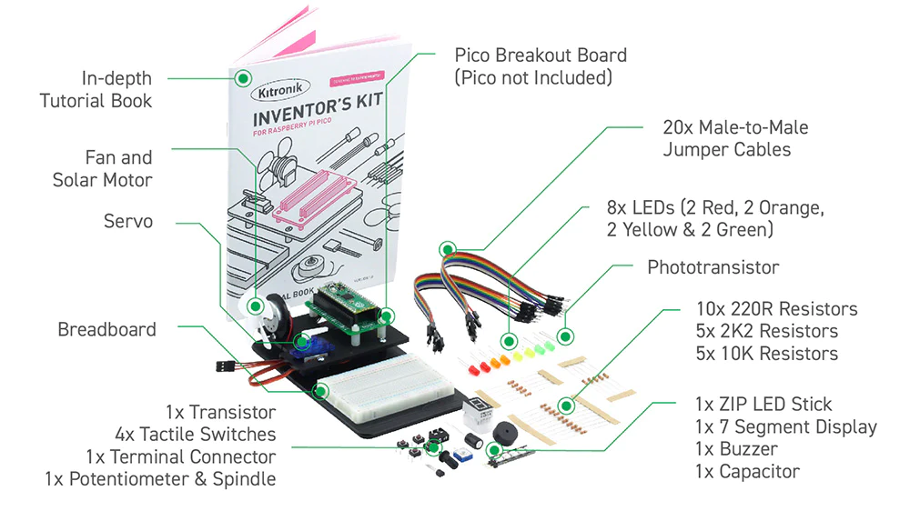
What's in the box?
- 1 x Full-colour instruction booklet.
- 1 x Kitronik injection moulded Inventor's prototyping mounting plate.
- 1 x Laser cut Pico mounting plate and fixings.
- 1 x Pico Pin Breakout Board.
- 1 x Kitronik 5 LED ZIP stick with pins.
- 1 x Mini 180 Degree Resin Gear Servo SG90.
- 1 x 7 segment display.
- 4 x Push switch.
- 2 x Red 5mm LED.
- 2 x Green 5mm LED.
- 2 x Yellow 5mm LED.
- 2 x Orange 5mm LED.
- 10 x 220Ω resistor.
- 5 x 2.2kΩ resistor.
- 5 x 10kΩ resistor.
- 1 x 3mm Phototransistor.
- 1 x Transistor (NPN BC337).
- 1 x Fan blade.
- 1 x Motor.
- 1 x Piezo element buzzer.
- 20 x MM jumper wires.
- 1 x 470uF electrolytic capacitor.
- 1 x Terminal connector.
- 1 x Potentiometer & finger adjust spindle.
Video: https://youtu.be/RhOw0qr_QLo
Requires:
- 1 x Raspberry Pi Pico with pre-soldered headers.
- 1 x Phillips Screwdriver.
- 1 x Terminal Block Screwdriver.
- 1 x Micro USB Cable.
- Thonny editor.
Resources:
The table below contains additional resources for each of the included experiments. This includes; Video walk-throughs for each and code that can be copied and then pasted into an editor, such as Thonny.

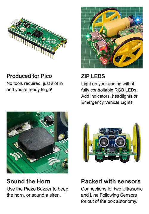
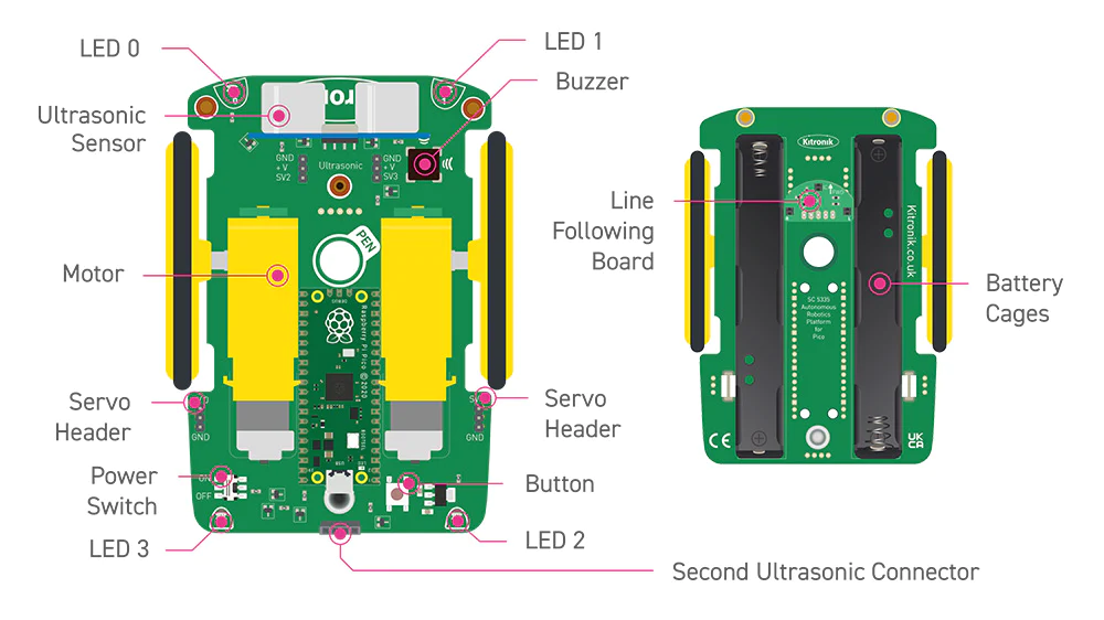
The Kitronik Autonomous Robotics Platform Pico, a fun and hands-on introduction to Robotics with the Raspberry Pi Pico.
The Kitronik Autonomous Robotics Platform for Raspberry Pi Pico is a fun and hands-on introduction to buggy robotics. The easy to follow booklet provided with the kit guides you through all of the steps required for you to take control of your robot. The Robotics Platform has been designed to grow with you and provided additional servo and ultrasonic sensor connectors for more advanced projects. This buggy requires a Raspberry Pi Pico with pin headers attached, you can obtain a Raspberry Pi Pico with headers attached here.
The kit is supplied with the autonomous robotics platform chassis, 2 wheels and tyres, a Kitronik line-following sensor board, and an ultrasonic sensor. The kit requires no soldering and only minimal mechanical assembly. Fit the tyres to the wheels, push the wheels onto the pre-mounted motors and both the line following sensor and ultrasonic distance sensor plug straight into the board. Once put together, push the Raspberry Pi Pico into the onboard connector, add 4 x Alkaline AA batteries to the battery holders underneath and you are done. Your robot buggy is ready for instruction.
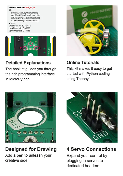
The included booklet guides you through every step of getting to know your robot. It contains a detailed assembly guide, info on preparing the Raspberry Pi Pico, instructions for installing an editor (Thonny), and instructions on how to write code for every feature of the Robotics Platform. No corner of the board is left unexplained.
As well as the easy to follow getting started guide, we have also produced online tutorials which go into more detail on coding the key features of the board. The links to the tutorials can be found in the resources section at the foot of this page.
To help make programming the robot as simple as possible, Kitronik has developed a set of Micropython modules, which can be found here. More information on this can be found in the booklet supplied with the kit. If you aren't familiar with GIT, we've created an online beginners guide to help you get up to speed. You can find the guide here (https://kitronik.co.uk/GitGuide).
Features:
- A fun and hands-on introduction to buggy robotics.
- The Robotics Platform has been designed to grow with you, start small then add complexity later.
- The kit ships with a detailed guide booklet backed up with freely available online tutorials.
- The autonomous robotics platform introduces the user to light, movement, and sensing so the robot can be as hands-on or hands-off as want it to be.
- Program your buggy to react to the world around it.
- Learn to code with MicroPython, using our simple to follow guides and the beginner-friendly Thonny editor.
- Just add the Raspberry Pi Pico, some alkaline batteries, and some code and watch your buggy come to life!
- This buggy is not supplied with a Pico, you can obtain a Raspberry Pi Pico here.
What's in the box?
- 1 x Autonomous robotics buggy chassis PCB.
- 2 x Kitronik 5 spoke wheels and tyres.
- 1 x Kitronik line following sensor board.
- 1 x Ultrasonic Sensor.
Dimensions:
- PCB Length: 126mm.
- PCB Width: 80mm.
- Wheel Diameter (with tire): 67.5mm.
Video: https://youtu.be/vPd4gt_Gt4U
Requires:
Resources:
- Kitronik Online Tutorials, using the Pico-ARP;
- Motors.
- Lights, switch, and buzzer.
- Line Following Sensors.
- Ultrasonic Distance Sensor.
- Using the servo connectors.
- First steps with the Raspberry Pi Pico, MicroPython, and Thonny.
- Kitronik Beginners guide to GitHub.
- A practical guide to Modules, Micro Python and the Raspberry Pi Pico.
- Kitronik Micropython modules for ARP-Pico.
- Pico Datasheet.

- Getting started with MicroPython on the Pico.
- Thonny, the beginner-friendly editor.

Add motor driving capability to the microbit with the Kitronik compact motor driver board for the BBC micro:bit. This motor driver board allows two motors to be driven simultaneously with forward, reverse & stop control, making it ideal for designs such as buggies. The board has built-in short circuit, over current and thermal protection.
The board includes an integrated Edge Connector for your BBC micro:bit to easily slot into. It also features external connections to the button A and button B inputs. This allows additional switches/inputs to be connected to the motor driver board and the state of these can then be read by the BBC micro:bit.
There are 2 additional inputs/outputs. These can be used for connecting a range of parts and can be used in either digital or analogue modes.
Power is provided via either a terminal block or servo style connector, the supply is then controlled by an on/off power switch to the board. There is a green LED to indicate when the board is turned on. The board also produces a regulated 3V supply that is fed into the 40 way connector to power the inserted BBC micro:bit, removing the need to power the BBC micro:bit directly.
Kitronik has produced a set of custom blocks for the MakeCode editor to simplify using the Compact motor driver board. To add them to the editor, select the cog icon in the top right of the editor. Then, select Extensions from the drop-down menu and in the search bar type and enter Kitronik. Pick the Kitronik motor driver tile from the list and the new blocks will be added to the menu in the editor.
Features- Ideal for designs such as buggies and other robotics projects.
- Drive 2 motors with full forward, reverse and stop control.
- Terminal blocks for easy connection of motors and inputs.
- The 2 additional inputs/outputs can be used in either digital or analogue modes.
- This board also features an on/off switch and power status LED.
- Includes Edge Connector for the BBC micro:bit to slot into.
- Provides regulated power to the BBC micro:bit.
- Access the other BBC micro:bit pins easily and conveniently.
- Program with the MakeCode editor or with python.
Example usage
What's in the box?
1 x Compact Motor Driver Board for the BBC micro:bit.
Dimensions
- Length: 68mm.
- Width: 46.5mm.
- Height: 10.6mm.
- PCB Thickness: 1.6mm.
Video: https://youtu.be/5wZISb9fRs4
You will also need....
- A micro:bit.
- USB Cable.
- Power Supply.
- The following part is also required.
Resources
- Datasheet.
- Python example code.
- Tech Talks - live stream playback.

Make the RiPi Pico the hub of your next robot/buggy project with The Kitronik Simply Robotics Board for Raspberry Pi Pico.
The Kitronik Simply Robotics Board for Raspberry Pi Pico features 2 Dual H-Bridge Motor Driver ICs (capable of driving 2 brushed motors or 1 stepper motor) and 8 servo outputs (capable of driving standard and continuous rotation servos), all controlled from a Raspberry Pi Pico. The Raspberry Pi Pico is not included, a Pico with pre-soldered pin headers can be obtained separately here.
The Motor Driver ICs are capable of up to 1A per channel and can drive a variety of small motors, such as hobby motors and more. They feature built-in protection for overcurrent, which can be reset by power cycling the board. The board features standard 3-pin servo connectors which allow for servos to be plugged straight in without the need for additional adaptors or soldering.
The IO breakout provides connections to 5 GPIO pins, including the Analogue inputs on the Pico. These IO points allow input devices, for example, sensors, or output devices, such as ZIP LEDs, to be added to the board. The board also features 3 x holes for mounting the board to a surface or custom enclosure, the mounting holes are 3.3mm in diameter (M3 clearance).
Power is provided via a terminal block. The supply is controlled by an on/off power switch to the board. There is a green LED to indicate when the board is turned on. The board then produces a regulated supply which is fed into the connected Pico, removing the need to power the Pico separately. There are 3V and GND pins broken out on the additional header, which means external devices can also be powered.
Note:
- This board is not supplied with a Raspberry Pi Pico, a Pico with pre-soldered pin headers can be obtained separately here.
- This board is capable of continuous use at high currents. During such use, it may become hot.
Features
- Control up 8 servos and two motors (or a stepper motor) simultaneously with the Raspberry Pi Pico.
- Ample IO for advanced robotics projects.
- The onboard servo connectors are standard 3-pin servo connectors.
- The board also features 5 GPIO pins, including the Analogue inputs on the Pico. These IO points allow input devices, for example, sensors, or output devices, such as ZIP LEDs.
- Power is provided via a terminal block power input connector, with an on/off switch and power status LED.
- The Simply Robotics board will power all of the attached servos and provide the attached Pico with a regulated 3V supply.
- Additionally, there is built-in reverse polarity protection.
- Kitronik has produced example MicroPython class and example code showing its use.
Dimensions
- Length: 63mm.
- Width: 42mm.
- Max Height: 10mm.
- Mounting Holes Diameter: 3.3mm (M3)
What's in the box?
1 x Kitronik Simply Robotics for Raspberry Pi Pico.You will also need....
Raspberry Pi Pico with pin headers attached if you don't already own one.Resources

The Kitronik Klaw MK2 Robotic Gripper Kit/robot claw is the latest version of the original and popular Kitronik Klaw and is a great addition to any robotics or buggy project.
It has been carefully redesigned so that it is now also compatible with both the MOVE:mini Mk1 and Mk2. On Mk1 it can be mounted to the boot lid and on the MK2 it can be added to both the boot lid and the base plate. Extra holes were added and a slight change to the part which holds the servo was made to facilitate this.
It is controlled by a low-voltage servo which is included, this servo is used to open and close the Klaw.
At the rear of the unit are mounting points allowing it to be bolted to other items, such as buggies or robotic arms. Supply voltage: 3V to 6V. Supplied as a set of parts that require simple assembly, see the resources section below for build instructions.
Features
- Easily add a gripping Klaw to any robotics project.
- It is compatible with both :MOVE mini Mk1 and MK2.
- Servo-powered opening and closing with the servo included as a part of the kit.
- Easy to assemble.
Contents
1 x Mini 180 Degree Servo With Accessories.
5 x Laser Cut Perspex Parts.
1 x M3 Steel Washers.
2 x M3 x 16 Pozi PanSteel.
2 x M2 x 16 Pozi PanSteel.
1 x Printed Assembly Instructions.
Dimensions
- Closed Length: 85mm.
- Closed Width: 70mm.
- Open Length: 45mm.
- Open Width: 125mm.
- Height w/servo: 38mm.

Unlock the secrets of nature with code, engineering, and the Kitronik Smart Greenhouse Kit for BBC micro:bit!
The Kitronik Smart Greenhouse Kit for the BBC micro:bit provides an exciting way to learn about the relationship between plants and their environment. The user will learn how to monitor environmental conditions and then how to build automated systems.
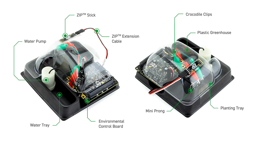
The kit comprises a two-part plastic greenhouse, Kitronik environmental control board, water pump, Kitronik ZIP Stick, and Mini Prong soils moisture sensor. Also included are 5 crocodile clips, ZIP extension cable and a small screwdriver. Just add a micro:bit, seeds, and then some water and you will have everything you need!
The kit also ships with detailed instructions that will get you up and cultivating in no time. Additionally, there are 7 online MakeCode tutorials. They cover everything from gathering sensor data and having the system automatically react to it, to visual user interfaces and more.
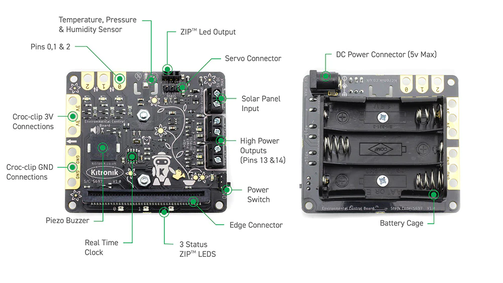
At the heart of the micro:bit controlled Kitronik Smart Greenhouse Kit is the Kitronik environmental control board. This board provides a variety of sensor inputs and connection points for the BBC micro:bit (V1 & V2) and provides the ability to control outputs for devices such as a water pump, fan, servo or heater pad.
The environmental control board can be coded with the MakeCode editor and Kitronik has produced a set of custom blocks to make the job as simple as possible. The blocks can be added via the add Extensions function in the editor by searching “Kitronik” or from https://github.com/KitronikLtd/pxt-kitronik-smart-greenhouse.
The default crop for these types of experiments is often cress, as it is quick growing, requires little tending, and can be harvested when they are approximately 5cm tall (within a few days). There are other sprouting plants, such as sprouting white mustard, which also grow quickly and can be harvested when they are 5cm tall. You can also look into micro-herbs/micro-greens. Once you have chosen your preferred crop type you then need to choose a suitable soil.
Note:
- This kit does not come with a BBC micro:bit, available separately here > BBC micro:bit.
- This kit is not waterproof. If you get the board wet, please turn it off and allow it to fully dry. The risk of shock is very small, but be cautious.
- Due to electrolysis and the damp environment, the electrodes on the Mini Prong Moisture Sensor will degrade slowly over time. Please see our general safety advice for more information.
Features
- Build automated growing systems that react to changeable environmental conditions.
- This kit is compatible with both micro:bit V1 and microbit V2.
- The kit comes with detailed assembly and coding instructions.
- At the heart of the kit is the kitronik Environmental control board, designed to be the control hub for this kit.
- Key features of the Environmental control board are;
- It features a number of sensor inputs that can be coded to control the board's outputs.
- There is an onboard BME 280 environmental temperature, barometric pressure and humidity sensor and a separate Real-Time Clock (RTC).
- The board also features an onboard piezo buzzer, 2 1A outputs (ideal for a water pump, heater pads or fan), 3 status ZIP LEDs, a ZIP LED expansion connector and servo output. In addition to these, 3 BBC micro:bit pins are broken out to croc-clip connections as further inputs and outputs, along with pads for 3V and GND.
- It can be powered via the onboard 3xAA battery holder or the 2.1mm DC Jack, and the power is controlled via the on/off switch with an adjacent LED indicator.
- There are also 7 online MakeCode tutorials that introduce you to all of the features of the board.
- Crops such as cress, sprouting white mustard and micro-herbs/micro-greens are ideal for use with this kit.
- Code it with the MakeCode editor using our custom code blocks.
- The Kit can be powered by 3 x AA Batteries or a plug-in power supply.
What's in the box?
2 x Moulded plastic greenhouse enclosure parts.
1 x Kitronik Environmental Control Board for micro:bit.
1 x Water Pump.
1 x Kitronik ZIP Stick.
1 x Mini Prong Moisture Sensor.
5 x Crocodile Leads.
1 x ZIP extension cable.
1 x Screwdriver.
1 x User guide Booklet.
Requires
- A web browser and an internet connection.
- One of the following; BBC micro:bit V2. or BBC micro:bit Starter Pack V2.
- 3 x AA Batteries or plug-in power supply.
- Seeds, such as cress.
- Soil.
- Optional Solar kit
- Adding a Solar Panel to the Environmental Control Board.
- Tech Talks - live stream playback.
Resources
- Environmental Control Board Datasheet.
- Mini Prong general safety advice.
- This example code. Monitors temperature, humidity, soil moisture, and makes use of the LEDs/ZIP LEDs.
Seven online MakeCode tutorials for the Kitronik Smart Greenhouse Kit;
- A - Visual Thermometer.
- B - ZIP LED hue.
- C - Auto-watering.
- D - Growlight.
- E - Timed watering.
- F - Water level sensing.
- G - Datalogging.
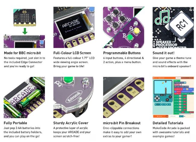
The Kitronik ARCADE for micro:bit is a fully assembled, compact and powerful gamer. The micro:bit(NOT INCLUDED) controls the gamer with a full colour LCD screen, perfect for playing retro games which have been coded and created via the popular MakeCode Arcade block editor!
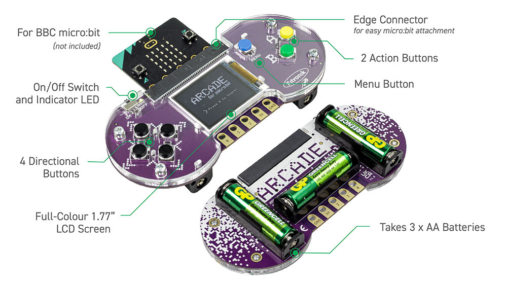
For teachers and students to get started it’s as simple as:
Plug in a micro:bit(NOT INCLUDED),
Download a pre-coded game or let them create their own using the wealth of resources available with the MakeCode ARCADE site
Let them play the lesson away while having fun and learning at the same time!
What's in the box?
1 x Arcade for micro:bit
Resources
- Kitronik Arcade for micro:bit Datasheet
- An extensive range of resources are currently available via the MakeCode ARCADE website
The Mini Prong soil sensor is a short version of the original Prong sensor that has been specially adapted for use with the Kitronik Greenhouse Kit for BBC micro:bit.
The Mini Prong soil moisture sensor for BBC micro:bit is a sensor board that can be connected to a BBC micro:bit with crocodile clips to monitor the moisture present in the soil. The two conductive tines are placed into the soil. Any water or moisture in the soil will conduct to give an analogue voltage that can be read by the BBC micro:bit.
Mini Prong is powered from the 3V supply of the BBC micro:bit. Use either the USB or JST connector on the BBC micro:bit to power the circuit.
The board has been designed to work with croc-clips, to connect between the Mini Prong and the BBC micro:bit.
When fitted to the Mini Prong moisture sensor, the micro:bit can be coded via any of the micro:bit editors, such as the Microsoft MakeCode editor. The Datasheet at the foot of this page includes technical information and a MakeCode blocks coding example.
Note:
- To ensure that the mini Prong moisture sensor has a long and fulfilling life, it is better to write your code to perform a moisture check every so often rather than continuously. When the check is performed continuously it promotes rapid erosion of the electrodes.
Features
- Measure soil moisture levels.
- Attach to the micro:bit with crocodile clips.
- Compatible with both BBC micro:bit V1 and BBC micro:bit V2.
- Write code for it with any micro:bit coding editor.
What's in the box?
1 x Prong Soil Moisture Sensor for microbit.
Resources
The Kitronik Pin Breakout for the Raspberry Pi Pico has been designed to offer an easy way of connecting additional circuitry and devices to the Pico. It also allows for moving the Pico between projects without the need to remove all of the jumper cables.
The Pico plugs into the two inner rows of sockets. The remaining two outer rows can then be used for connecting to external devices/circuits. The board has clear markings for each pin and the correct orientation for inserting the Pico is also clearly marked.
In order to use this board, the Pico should have soldered pin headers, it can then be firmly inserted into the board. Additionally, the board features 4 x M3 mounting holes to allow for fixing the board to projects/prototyping setups. Care was taken when designing the Pico Pin Breakout to maintain as small a footprint as possible.
Features
- It offers a convenient interface for controlling additional circuitry with the Raspberry Pi Pico.
- The board features 2 x rows of sockets that a Pico with soldered pin headers can slot straight into.
- The outer rows of sockets can be used to connect any of the Pico i/o pins to a project/prototype.
- Use jumper wires, soldering is not required.
- Raspberry Pi Pico prototyping made easy.
What's in the box?
1 x Kitronik Pin Breakout for the Raspberry Pi Pico.
Resources
The Breadboard breakout for the BBC micro:bit allows the user to plug a BBC micro:bit into a standard 2.54mm pitch breadboard. Two 11 way pin headers are used to make connections into the breadboard.
The micro:bit slots into the edge connector on the top side of the PCB. No extra tools are required for installation. The front of the BBC micro:bit (the side with the LEDs) should be inserted facing the same side as the 3V pin.
The edge connector has connections on only one side, so if the BBC micro:bit is inserted in reverse orientation, it will not work.
The PCB is designed to plug across the middle slot of a breadboard, the same placement as an IC component.
Features
- The microbit slots into the on-board edge connector.
- This breakout board plugs straight across the middle slot of a standard 2.54mm pitch breadboard, just like an IC component.
- The microbits pins are broken out to 2 x 11 way header pins.
- Use jumper wires to connect from the header pins to the breadboard.
- No tools or soldering required for installation.
- microbit to breadboard prototyping made easy.
What's in the box?
1 x Breadboard breakout for the BBC micro:bit.
You will also need......
Resources
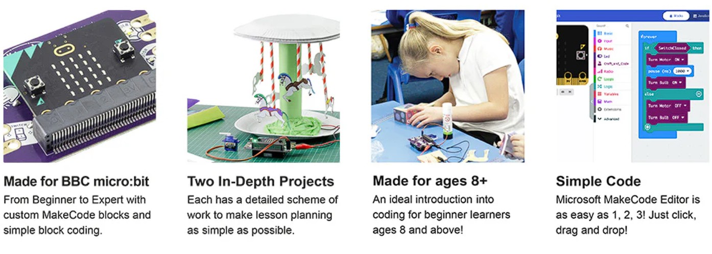
Get creative by combining the BBC micro:bit and electrical components with Kitronik Craft & Code! Designed by Teachers and tested by Pupils for learners aged 8+
The Kitronik Craft & Code for BBC micro:bit is a fun and engaging way for students to learn about coding as part of wider craft-based projects. Using any version of the BBC micro:bit, this board allows beginners 8+ to design and control various craft projects using MakeCode for micro:bit. MakeCode is an intuitive, block-based coding environment. Everything that is needed is contained within the box, except for the standard classroom craft materials each project requires and the components listed in the 'Requires' section below.
The kit ships with a getting started booklet. The booklet serves as an introduction to the board and the additional supplied parts. It also introduces the user to the micro:bit, the MakeCode editor, writing code with the editor, and how to run programs on the micro:bit. Additionally, the booklet contains two full projects, the documentation walks the user through each project step, including creating the code.
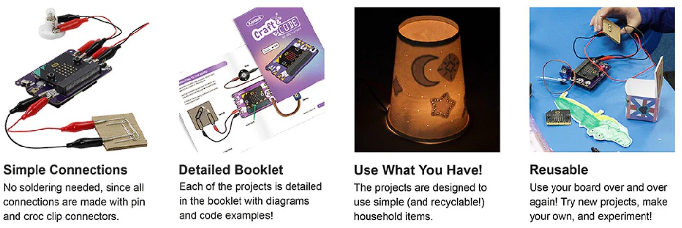
Project 1: Carousel Project - This project will help you craft your tabletop carousel, and then program it to make it run like the real thing! Decorate your carousel with pencils, paint or mixed materials to make it your own. Bonus: We have even included instructions on how to make your own fully-operating safety barrier!
Project 2: Night Light Project - This project will help you to craft your touch-operated night light. Decorate your lampshade with stars, planets or your own design to really make it your own. Touch-operated night lights allow you to choose your brightness level to suit your needs.
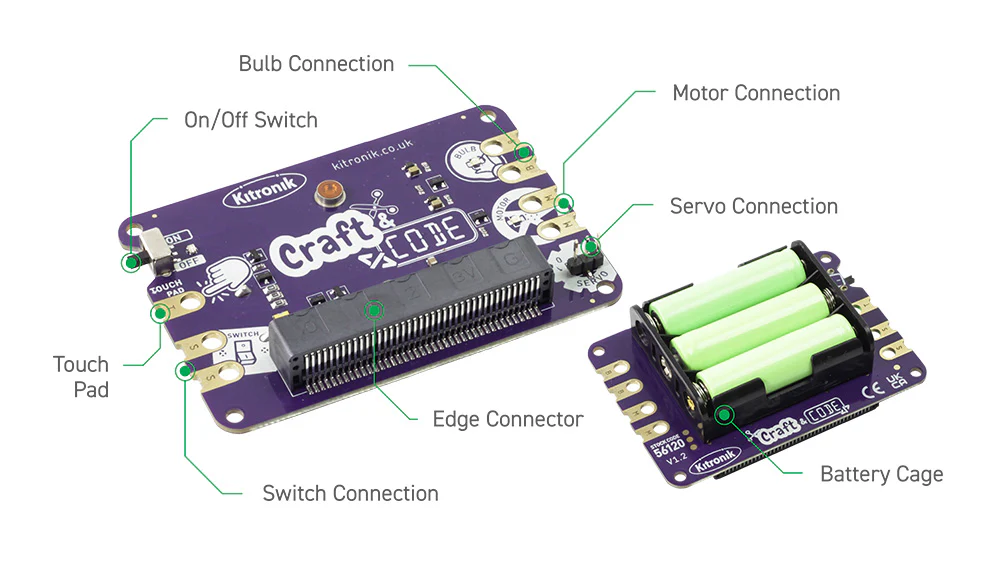
Hardware: The kit is supplied with the following hardware; Craft and Code board, a servo, a motor, a pack of crocodile leads, a bulb holder, a bulb, and a finnboard board wheel --for use with the motor in one of the included projects. The hardware is connected to the board using crocodile leads, except for the servo, and the board is clearly marked for connecting the devices.
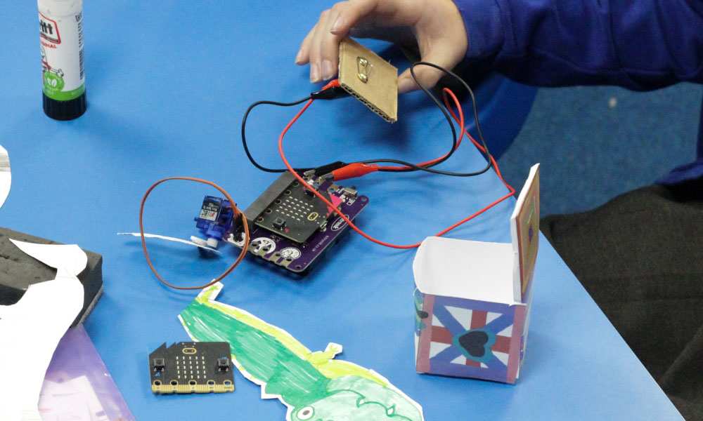
Power: The board requires 3 x AA batteries (Not included - available separately here.) The board features an AA battery cage on the underside. These batteries power the board, the inserted micro:bit, and the devices attached to the board. The operating voltage of the board is 3.5V - 4.5V, with a max current draw of 470mA (Typical - 350mA). If the board is powered on with no micro:bit inserted, it will draw approximately 9.5mA. To protect the batteries, there is an on/off switch on the board. See the Datasheet for more detailed electrical information.
Coding: The board has been designed for use with the MakeCode Blocks editor for micro:bit. Kitronik has designed a custom MakeCode extension to support the use of the Craft and Code board in the MakeCode editor. This extension contains all of the blocks required to take control of every aspect of the board and the hardware connected to it. It can be added by clicking on the Extensions tab. See the Datasheet for more detailed information on the blocks contained in the extension.
Note:
- A micro:bit is not included. The kit works with both v1 and V2 micro:bits, a V2 micro:bit can be obtained here.
- Batteries are not included. AA batteries can be obtained separately here.
- A USB cable is not included. A USB cable can be obtained separately here.
Features
- It is an innovative environment for beginners to learn about building circuits and constructing projects that incorporate electronics and code.
- The board works with micro:bit V1 & V2.
- The kit is supplied with a servo, a motor, a pack of crocodile leads, a bulb holder, a bulb, and a Finnboard board wheel.
- No tools are required, the included servo connects via a standard connector and all other devices are connected with crocodile leads.
- The board has clear markings to indicate how to connect each device correctly.
- The included printed guide acts as an introduction to the board, MakeCode, coding with the editor, and also includes two projects to work through.
- The projects contain step-by-step guides, including full code examples.
- Kitronik has designed a custom MakeCode extension to support the use of the Craft and Code board in the MakeCode editor.
- The Kitronik Extension features all of the blocks required to take control of the board's features.
- The board requires 3 x AA batteries, which provide power for the board, the micro:bit, and the connected devices.
- Additionally, there is an onboard on/off switch to help prolong the life of the batteries.
What's in the box?
1 x Kitronik Craft & Code boards.
5 x Crocodile Leads, 1/2 a pack of 10.
1 x In-Line Geared TT Hobby Motor with wires - Croc Clips.
1 x Mini 180 Degree Resin Gear Servo SG90.
1 x MES Lamp Holder (with Plastic Base)
1 x MES Bulb 4.5V.
1 x Finnboard wheel, for use as a motor accessory.
1 x Craft and Code Booklet.
Resources
- BBC micro:bit.
- AA Batteries.
- USB Cable.
- General craft materials are required for each experiment.
- Craft and Code board Datasheet.
- Motor Datasheet.
- All Craft and Code assets.
- Booklet Answers Page.