
Raspberry Pi


Watch Jeff Geerling's Raspberry Pi Zero 2 W Review
Raspberry Pi Zero 2 W is the latest product in our most affordable range of single-board computers. The successor to the breakthrough Raspberry Pi Zero W, Raspberry Pi Zero 2 W is a form factor–compatible drop-in replacement for the original board.
The board incorporates a quad-core 64-bit Arm Cortex-A53 CPU, clocked at 1GHz. At its heart is a Raspberry Pi RP3A0 system-in-package (SiP), integrating a Broadcom BCM2710A1 die with 512MB of LPDDR2 SDRAM. The upgraded processor provides Raspberry Pi Zero 2 W with 40% more single-threaded performance, and five times more multi-threaded performance, than the original single-core Raspberry Pi Zero.
Raspberry Pi Zero 2 W offers 2.4GHz 802.11 b/g/n wireless LAN and Bluetooth 4.2, along with support for Bluetooth Low Energy (BLE), and modular compliance certification.
The board has a microSD card slot, a CSI-2 camera connector, a USB On-The-Go (OTG) port, and an unpopulated footprint for a HAT-compatible 40-pin GPIO header. It is powered via a micro USB socket. Video output is via a mini HDMI port; composite video output can easily be made available via test points if needed.
Sharing the same form factor as the original Raspberry Pi Zero, Raspberry Pi Zero 2 W fits inside most existing Raspberry Pi Zero cases.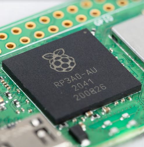
Specifications
Form factor: 65mm × 30mm
Processor: Broadcom BCM2710A1, quad-core 64-bit SoC (Arm Cortex-A53 @ 1GHz)
Memory: 512MB LPDDR2
Connectivity:
• 2.4GHz IEEE 802.11b/g/n wireless LAN, Bluetooth 4.2, BLE, onboard antenna
• 1 × USB 2.0 interface with OTG
• HAT-compatible 40-pin I/O header footprint
• microSD card slot
• Mini HDMI port
• CSI-2 camera connector
Video:
• HDMI interface
• Composite video
Multimedia:
• H.264, MPEG-4 decode (1080p30)
• H.264 encode (1080p30)
• OpenGL ES 1.1, 2.0 graphics
Input power: 5V DC 2.5A
Operating temperature: -20°C to 70°C
What's in the box?
1 x Raspberry Pi Zero 2 W
You might also need...
The Raspberry Pi board comes without the below items. Have a look at what else you still need to get.
- download and install Raspberry Pi OS using Raspberry Pi imager or grab a uSD card with Raspberry Pi OS preloaded
- a USB micro B power supply
- a mini HDMI cable or HDMI mini adapter
- an enclosure/case for your Pi Zero
- a keyboard and mouse
Resources
- Raspberry Pi Operating System Downloads https://www.raspberrypi.org/downloads/
Getting Started with Raspberry Pi - For a step-by-step guide to getting your Pi up and running, check out our online Getting started guide.
- There are loads of projects to get started on with your Raspberry Pi Zero in our learning resources area
Production lifetime: Raspberry Pi Zero 2 W will remain in production until at least January 2028
Compliance: For a full list of local and regional product approvals,
please visit pip.raspberrypi.com
WARNINGS
• Any external power supply used with Raspberry Pi Zero 2 W shall comply with relevant regulations and standards applicable in the country of intended use.
• This product should be operated in a well-ventilated environment, and if used inside a case, the case should not be covered.
• Whilst in use, this product should be placed on a stable, flat, non-conductive surface, and should not be contacted by conductive items.
• The connection of incompatible devices to Raspberry Pi Zero 2 W may affect compliance, result in damage to the unit, and invalidate the warranty.
• All peripherals used with this product should comply with relevant standards for the country of use and be marked accordingly to ensure that safety and performance requirements are met. These articles include but are not limited to
keyboards, monitors, and mice when used in conjunction with Raspberry Pi Zero 2 W.
• The cables and connectors of all peripherals used with this product must have adequate insulation so that relevant safety requirements are met.
SAFETY INSTRUCTIONS
To avoid malfunction or damage to this product, please observe the following:
• Do not expose to water or moisture, or place on a conductive surface whilst in operation.
• Do not expose to heat from any source; Raspberry Pi Zero 2 W is designed for reliable operation at normal ambient temperatures.
• Take care whilst handling to avoid mechanical or electrical damage to the printed circuit board and connectors.
• Whilst it is powered, avoid handling

Description:
The Raspberry Pi Build HAT combines the power of Raspberry Pi computing with LEGO® hands-on learning to enable a fun and creative learning experience for students, teachers and makers.
The Build HAT is compatible with the most recent generation of LEGO® Technic™ motors, and with sensors included in the LEGO® Education SPIKE™ Prime portfolio.
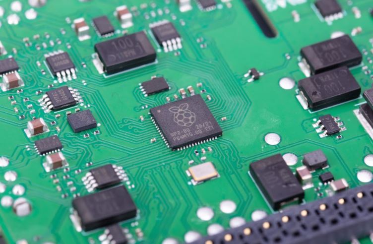
The Build HAT is the second Raspberry Pi product, after Raspberry Pi Pico, to be powered by the Raspberry Pi RP2040 microcontroller.
Specifications:
• Controls up to 4 motors and sensors.
• Powers the Raspberry Pi (when used with a suitable external PSU).
• Easy to use from Python on the Raspberry Pi.
What's in the box?
1 x Raspberry Pi Build HAT for LEGO
Build HAT Links
- Raspberry Pi Build HAT Website
- Getting started with the Raspberry Pi Build HAT
- Raspberry Pi Build HAT Projects
- Raspberry Pi Build HAT Documentation and Python Library
- LEGO Device compatibility
- Build HAT Announcement Article
LEGO Links

This Official Rapsberry Pi PSU supports up to 2.5A of current, so it won't let you down when powering hungry devices through your Raspberry Pi 3 Model B, Zero and Pico
Output
- Output voltage: 5.1V DC
- Minimum load current: 0.0A
- Nominal load current: 2.5A
- Maximum power: 12.5W
- Load regulation: ±5%
- Line regulation: ±2%
- Ripple & noise: 120mVp-p
- Rise time: 100ms maximum to regulation limits for DC outputs
- Turn-on delay: 3000ms maximum at nominal input AC voltage and full load
- Protection: Short circuit protection
Overcurrent protection
- Efficiency: 80.73% minimum (output current from 100%, 75%, 50%, 25%)
- Output cable: 1.5m 18AWG
- Output connector: micro USB
Input
- Voltage range: 100–240Vac (rated) 96–264Vac (operating)
- Frequency: 50/60Hz ±3Hz
- Current: 0.5A maximum
- Power consumption (no load): 0.075W maximum
- Inrush current: No damage shall occur and the input fuse shall not blow
What's in the box?
1 x Official Power Supply
You will also need a euro plug adapter
WARNINGS
• This product should be operated in a well-ventilated environment.
• The connection of incompatible devices to this power supply may affect compliance, result in damage to the unit and invalidate the warranty.
SAFETY INSTRUCTIONS
To avoid malfunction or damage to this product please observe the following:
• Do not expose to water or moisture, or place on a conductive surface whilst in operation.
• Do not expose to heat from any source; this is designed for reliable operation at normal ambient room temperatures.
• Do not attempt to open or remove the power supply case.

Power your Raspberry Pi Build HAT projects with the Raspberry Pi Build HAT Power Supply. This 48W power supply will power the Build HAT and connected LEGO® Technic™ motors, as well as your Raspberry Pi computer.
Compatible with LEGO Technic motors and sensors included in the LEGO® Education SPIKE™ Portfolio, the Build HAT combines the power of Raspberry Pi computing with easy building opportunities to help you make creative and robust projects.
Specifications
Output
- Output voltage: +8.0V DC
- Minimum load current: 0.01A
- Nominal load current: 6.0A
- Maximum power: 48.0W
- Load regulation: ±5%
- Line regulation: ±5%
- Ripple & noise: 200mVp-p
- Rise time: 100ms maximum to regulation limits for DC outputs
- Turn-on delay: 3000ms maximum at nominal input AC voltage and full load
- Protection: Short circuit protection
- Overcurrent protection
- Overvoltage protection
- Efficiency: 87.77% minimum (output current from 100%, 75%, 50%, 25%)
- Output cable: 1.5m 16AWG
- Output connector: Barrel connector 5.5mm × 2.1mm × 11mm Centre positive
Input
- Voltage range: 100-240Vac (rated)
- 96-264Vac (operating)
- Frequency: 50/60Hz ±3Hz
- Current: 1.2A maximum
- Power consumption (no load): 0.1W maximum
- Inrush current: No damage shall occur and the input fuse shall not blow
What's in the box?
1 x Official 48W power supply for Build HAT
You will also need a euro plug adapter

This adapter kit was created for the Raspberry Pi Zero. It includes all the adapters you need to get your Raspberry pi Zero going.
What's in the box?
1 x pin header 2x20
1 x Official Raspberry Pi male mini HDMI to female HDMI adapter
1 x Official Raspberry Pi OTG male micro USB to female USB A adapter

It features:
• Dual-core Arm Cortex-M0 @ 133MHz
• 264KB of on-chip RAM
• Support for up to 16MB of off-chip Flash memory via a QSPI bus
• DMA controller
• Interpolator and integer divider peripherals
• 30 GPIO pins, 4 of which can be used as analogue inputs
• 2 × UARTs, 2 × SPI controllers, and 2 × I2C controllers
• 16 × PWM channels
• 1 × USB 1.1 controller and PHY, with host and device support
• 8 × Raspberry Pi Programmable I/O (PIO) state machines
• USB mass-storage boot mode with UF2 support, for drag-and-drop programming
Please see the RP2040 datasheet for more details
and Hardware Design with RP2040
To date, RP2040 has only been available on Raspberry Pi Pico, and as a component to a limited number of partners. We now cover the availability of RP2040 as a component to the broad market in single-unit quantities. Bulk quantities on reels of 500.

Raspberry Pi Pico W is a microcontroller board based on the Raspberry Pi RP2040 microcontroller chip.
Raspberry Pi Pico W has been designed to be a low cost yet flexible development platform for RP2040, with a 2.4GHz wireless interface and the following key features:
• RP2040 microcontroller with 2MB of flash memory
• On-board single-band 2.4GHz wireless interfaces (802.11n)
• Micro USB B port for power and data (and for reprogramming the flash)
• 40 pin 21mmx51mm 'DIP' style 1mm thick PCB with 0.1" through-hole pins also with edge castellations
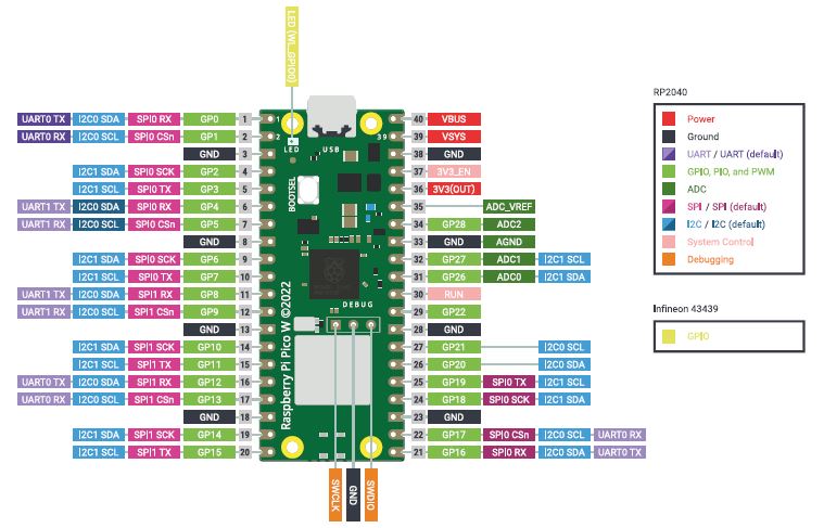
◦ Exposes 26 multi-function 3.3V general purpose I/O (GPIO)
◦ 23 GPIO are digital-only, with three also being ADC capable
◦ Can be surface mounted as a module
• 3-pin ARM serial wire debug (SWD) port
• Simple yet highly flexible power supply architecture
◦ Various options for easily powering the unit from micro USB, external supplies or batteries
• High quality, low cost, high availability
• Comprehensive SDK, software examples and documentation
For full details of the RP2040 microcontroller please see the RP2040 Datasheet book. Key features include:
• Dual-core cortex M0+ at up to 133MHz
◦ On-chip PLL allows variable core frequency
• 264kByte multi-bank high performance SRAM
• External Quad-SPI Flash with eXecute In Place (XIP) and 16kByte on-chip cache
• High performance full-crossbar bus fabric
• On-board USB1.1 (device or host)
• 30 multi-function general purpose I/O (four can be used for ADC)
◦ 1.8-3.3V I/O voltage
• 12-bit 500ksps analogue to digital converter (ADC)
• Various digital peripherals
◦ 2 × UART, 2 × I2C, 2 × SPI, 16 × PWM channels
◦ 1 × timer with 4 alarms, 1 × real time clock
• 2 × programmable I/O (PIO) blocks, 8 state machines in total
◦ Flexible, user-programmable high-speed I/O
◦ Can emulate interfaces such as SD card and VGA
NOTE - Raspberry Pi Pico W I/O voltage is fixed at 3.3V
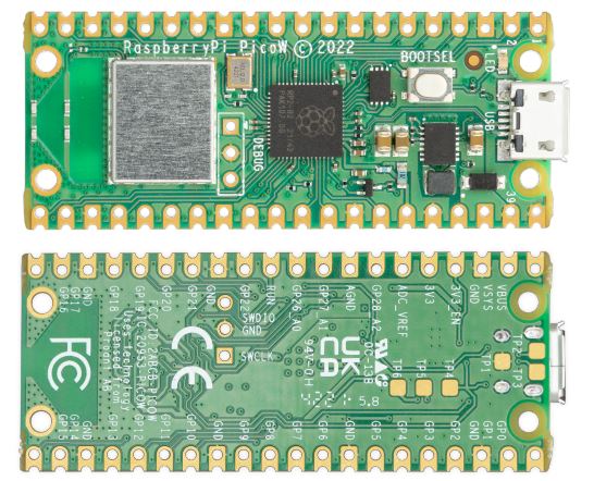
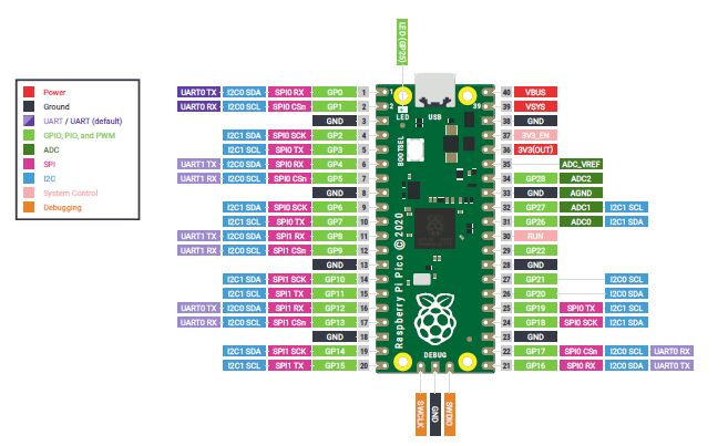
Raspberry Pi Pico W provides a minimal yet flexible external circuitry to support the RP2040 chip: flash memory (Winbond W25Q16JV), a crystal, power supplies and decoupling, and USB connector. The majority of the RP2040 microcontroller pins are brought to the user IO pins on the left and right edge of the board. Four RP2040 I/O are used for internal functions: driving an LED, on-board switch mode power supply (SMPS) power control, and sensing the system voltages.
Pico W has an on-board 2.4GHz wireless interface using an Infineon CYW43439. The antenna is an onboard antenna licensed from ABRACON (formerly ProAnt). The wireless interface is connected via SPI to the RP2040.
Pico W has been designed to use either soldered 0.1-inch pin-headers (it is one 0.1-inch pitch wider than a standard 40-pin DIP package), or to be positioned as a surface mountable 'module', as the user I/O pins are also castellated. There
are SMT pads underneath the USB connector and BOOTSEL button, which allow these signals to be accessed if used as a reflow-soldered SMT module.
What's in the box?
1 x Raspberry Pi Pico WH with manufacturer pre-soldered headers
Resources
- Support docs available here
- Getting Started with Raspberry Pi Pico (pdf), C/C++ Development with the Pico and other RP2040-based microcontroller boards
- Raspberry Pi Pico W Datasheet (pdf)
- Raspberry Pi Pico Datasheet (pdf), An RP2040-based microcontroller board
- Pico Python SDK (pdf), A MicroPython Environment for the RP2040 Microcontroller
- Pico C/C++ SDK (pdf), Libraries and Tools for C/C++ Development on the RP2040 Microcontroller
- RP2040 Datasheet (pdf), A microcontroller by Raspberry Pi
- Mating Plug for the Debug connector, SHR-03V-S-B, we have never tested before though :)
- Quick-Start the Pico W WiFi with CircuitPython, by Liz Clark, at learn.adafruit
- A New Challenger in MCU Platform – Raspberry Pi Pico, an article about Raspberry Pi Pico and RP2040
- Raspberry Pi Pico Vs Arduino UNO R3, an article to compare the spec of RPi Pico and Arduino UNO R3
- A New Challenger in MCU Platform – Raspberry Pi Pico, an article about Raspberry Pi Pico and RP2040
- Raspberry Pi Pico Vs Arduino UNO R3, an article to compare the spec of RPi Pico and Arduino UNO R3

This is the Pico model H with pre-soldered connectors. Raspberry Pi Pico H is fitted with a pre-soldered 40-way header and 3-pin JTAG connector, for greater ease of use in hobbyist and industrial applications.
https://www.raspberrypi.org/blog/raspberry-pi-silicon-pico-now-on-sale/
https://www.raspberrypi.org/products/raspberry-pi-pico/
https://www.youtube.com/watch?v=ZY-HrRGCQ4w
YouTube video on Pico by Jeff Geerling
Raspberry Pi Pico, a microcontroller board built on silicon designed here at Raspberry Pi.
Whether you choose to use our C/C++ SDK, or the official MicroPython port, everything you need to get started is here. You’ll also find links to the technical documentation for both the Raspberry Pi Pico microcontroller board and our RP2040 microcontroller chip.
Board Specifications
- RP2040 microcontroller chip designed by Raspberry Pi in the United Kingdom
- Dual-core ARM Cortex M0+ processor, flexible clock running up to 133 MHz
- 264kB of SRAM, and 2MB of on-board Flash memory
- Castellated module allows soldering direct to carrier boards
- USB 1.1 Host and Device support
- Low-power sleep and dormant modes
- Drag & drop programming using mass storage over USB
- 26 multi-function GPIO pins
- 2×SPI, 2×I2C, 2×UART, 3×12-bit ADC, 16×controllable PWM channels
- Accurate clock and timer on-chip
- Temperature sensor
- Accelerated floating point libraries on-chip
- 8×Programmable IO (PIO) state machines for custom peripheral support
Download Pinout Diagram
Documentation
Documentation for the Raspberry Pi Pico board and the RP2040 microcontroller:
Raspberry Pi Pico Datasheet
An RP2040-based microcontroller board
RP2040 Datasheet
A microcontroller by Raspberry Pi
Hardware design with the RP2040
Using the RP2040 microcontroller to build boards and products
Getting Started with Raspberry Pi Pico
C/C++ development with the Pico and other RP2040-based microcontroller boards
Pico C/C++ SDK
Libraries and tools for C/C++ development on the RP2040 microcontroller
Pico Python SDK
A MicroPython environment for the RP2040 microcontroller
The API level Doxygen documentation for the Raspberry Pi Pico C/C++ SDK is available as a micro-site.
1 x Raspberry Pi Pico H
Resources
- Support docs available here
- Getting Started with Raspberry Pi Pico (pdf), C/C++ Development with the Pico and other RP2040-based microcontroller boards
- Raspberry Pi Pico W Datasheet (pdf)
- Raspberry Pi Pico Datasheet (pdf), An RP2040-based microcontroller board
- Pico Python SDK (pdf), A MicroPython Environment for the RP2040 Microcontroller
- Pico C/C++ SDK (pdf), Libraries and Tools for C/C++ Development on the RP2040 Microcontroller
- RP2040 Datasheet (pdf), A microcontroller by Raspberry Pi
- Mating Plug for the Debug connector, SHR-03V-S-B, we have never tested before though :)
- Quick-Start the Pico W WiFi with CircuitPython, by Liz Clark, at learn.adafruit
- A New Challenger in MCU Platform – Raspberry Pi Pico, an article about Raspberry Pi Pico and RP2040
- Raspberry Pi Pico Vs Arduino UNO R3, an article to compare the spec of RPi Pico and Arduino UNO R3
- A New Challenger in MCU Platform – Raspberry Pi Pico, an article about Raspberry Pi Pico and RP2040
- Raspberry Pi Pico Vs Arduino UNO R3, an article to compare the spec of RPi Pico and Arduino UNO R3

Raspberry Pi Pico W is a microcontroller board based on the Raspberry Pi RP2040 microcontroller chip.
Raspberry Pi Pico W has been designed to be a low cost yet flexible development platform for RP2040, with a 2.4GHz wireless interface and the following key features:
• RP2040 microcontroller with 2MB of flash memory
• On-board single-band 2.4GHz wireless interfaces (802.11n)
• Micro USB B port for power and data (and for reprogramming the flash)
• 40 pin 21mmx51mm 'DIP' style 1mm thick PCB with 0.1" through-hole pins also with edge castellations
◦ Exposes 26 multi-function 3.3V general purpose I/O (GPIO)
◦ 23 GPIO are digital-only, with three also being ADC capable
◦ Can be surface mounted as a module
• 3-pin ARM serial wire debug (SWD) port
• Simple yet highly flexible power supply architecture
◦ Various options for easily powering the unit from micro USB, external supplies or batteries
• High quality, low cost, high availability
• Comprehensive SDK, software examples and documentation
For full details of the RP2040 microcontroller please see the RP2040 Datasheet book. Key features include:
• Dual-core cortex M0+ at up to 133MHz
◦ On-chip PLL allows variable core frequency
• 264kByte multi-bank high performance SRAM
• External Quad-SPI Flash with eXecute In Place (XIP) and 16kByte on-chip cache
• High performance full-crossbar bus fabric
• On-board USB1.1 (device or host)
• 30 multi-function general purpose I/O (four can be used for ADC)
◦ 1.8-3.3V I/O voltage
• 12-bit 500ksps analogue to digital converter (ADC)
• Various digital peripherals
◦ 2 × UART, 2 × I2C, 2 × SPI, 16 × PWM channels
◦ 1 × timer with 4 alarms, 1 × real time clock
• 2 × programmable I/O (PIO) blocks, 8 state machines in total
◦ Flexible, user-programmable high-speed I/O
◦ Can emulate interfaces such as SD card and VGA
NOTE - Raspberry Pi Pico W I/O voltage is fixed at 3.3V
Raspberry Pi Pico W provides a minimal yet flexible external circuitry to support the RP2040 chip: flash memory (Winbond W25Q16JV), a crystal, power supplies and decoupling, and USB connector. The majority of the RP2040 microcontroller pins are brought to the user IO pins on the left and right edge of the board. Four RP2040 I/O are used for internal functions: driving an LED, on-board switch mode power supply (SMPS) power control, and sensing the system voltages.
Pico W has an on-board 2.4GHz wireless interface using an Infineon CYW43439. The antenna is an onboard antenna licensed from ABRACON (formerly ProAnt). The wireless interface is connected via SPI to the RP2040.
Pico W has been designed to use either soldered 0.1-inch pin-headers (it is one 0.1-inch pitch wider than a standard 40-pin DIP package), or to be positioned as a surface mountable 'module', as the user I/O pins are also castellated. There
are SMT pads underneath the USB connector and BOOTSEL button, which allow these signals to be accessed if used as a reflow-soldered SMT module.
What's in the box?
1 x Raspberry Pi Pico W
Resources
- Support docs available here
- Getting Started with Raspberry Pi Pico (pdf), C/C++ Development with the Pico and other RP2040-based microcontroller boards
- Raspberry Pi Pico W Datasheet (pdf)
- Raspberry Pi Pico Datasheet (pdf), An RP2040-based microcontroller board
- Pico Python SDK (pdf), A MicroPython Environment for the RP2040 Microcontroller
- Pico C/C++ SDK (pdf), Libraries and Tools for C/C++ Development on the RP2040 Microcontroller
- RP2040 Datasheet (pdf), A microcontroller by Raspberry Pi
- Mating Plug for the Debug connector, SHR-03V-S-B, we have never tested before though :)
- Quick-Start the Pico W WiFi with CircuitPython, by Liz Clark, at learn.adafruit
- A New Challenger in MCU Platform – Raspberry Pi Pico, an article about Raspberry Pi Pico and RP2040
- Raspberry Pi Pico Vs Arduino UNO R3, an article to compare the spec of RPi Pico and Arduino UNO R3
- A New Challenger in MCU Platform – Raspberry Pi Pico, an article about Raspberry Pi Pico and RP2040
- Raspberry Pi Pico Vs Arduino UNO R3, an article to compare the spec of RPi Pico and Arduino UNO R3

The Raspberry Pi Debug Probe is an inexpensive, all-in-one USB to serial debug and UART bridge. It provides the necessary hardware and cabling to support “plug and play” debugging of Raspberry Pi Pico and other microcontroller- and microprocessor-based platforms.
The Raspberry Pi Debug Probe provides both a processor serial debug interface (by default this is the ARM Serial Wire Debug interface) and an industry-standard UART interface. Both interfaces use a 3-pin debug connector, as specified in the Raspberry Pi 3-pin debug connector specification.
The Raspberry Pi Debug Probe is provided as a kit, containing the probe hardware in a plastic case, and a set of cables: a USB cable, and
three different types of debug cable to cover the vast majority of use cases.
While it has been designed primarily for use with Raspberry Pi debug targets, the Debug Probe provides standard CMSIS-DAP debug and UART interfaces over USB; it can therefore be used to debug other targets, or simply as a cost-effective USB-to-UART cable.
The Raspberry Pi Debug Probe is based on the Raspberry Pi Pico hardware design and runs the open-source Raspberry Pi Picoprobe software https://github.com/raspberrypi/picoprobe. Updating the firmware is accomplished in the same way as on a Raspberry Pi Pico, so it is straightforward to keep the unit up to date with the latest Picoprobe firmware, or to use a custom firmware.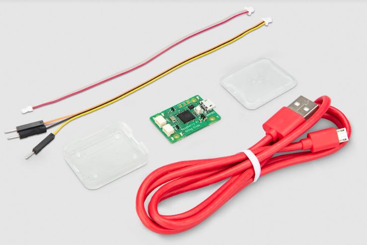
What's in the box?
1 x Debug Probe
1 x Probe plastic case
1 x USB A to USB micro B cable
3 x debug cables
Resources
- https://datasheets.raspberrypi.com/debug/debug-connector-specification.pdf
- Raspberry Pi Debug Probe product brief
- Raspberry Pi Debug Probe documentation
Debug Probe firmware v2.2.1 - there is a new firmware update for the Debug Probe available. Please use this link to download the update - https://github.com/

Please note: You will need to buy a different CSI cable for use with RPi 5 or ZERO.
Raspberry Pi Camera Module 3 is a compact camera from Raspberry Pi. It offers an IMX708 12-megapixel sensor with HDR, and features phase detection autofocus. Camera Module 3 is available in standard and wide-angle variants, both of which are available with or without an infrared cut filter.
Camera Module 3 can be used to take full HD video as well as stills photographs, and features an HDR mode up to 3 megapixels. Its operation is fully supported by the libcamera library, including Camera Module 3’s rapid autofocus feature: this makes it easy for beginners to use, while offering plenty for advanced users. Camera Module 3 is compatible with all Raspberry Pi computers. ( Excluding early Raspberry Pi Zero models, which lack the necessary FPC connector. Later Raspberry Pi Zero models require an adapter FPC, sold separately.)
The PCB size and mounting holes remain the same as for Camera Module 2.
The Z dimension differs: due to the improved optics, Camera Module 3 is several millimetres taller than Camera Module 2.
All variants of Camera Module 3 feature:
• Back-illuminated and stacked CMOS 12-megapixel image sensor (Sony IMX708)
• High signal-to-noise ratio (SNR)
• Built-in 2D Dynamic Defect Pixel Correction (DPC)
• Phase Detection Autofocus (PDAF) for rapid autofocus
• QBC Re-mosaic function
• HDR mode (up to 3 megapixel output)
• CSI-2 serial data output
• 2-wire serial communication (supports I2C fast mode and fast-mode plus)
• 2-wire serial control of focus mechanism
What's in the box?
1 x Raspberry pi camera module 3
Resources
Latest updates and news available at https://www.raspberrypi.com/products/camera-module-3/

Please note: You will need to buy a different CSI cable for use with RPi 5 or ZERO.
Raspberry Pi Camera Module 3 is a compact camera from Raspberry Pi. It offers an IMX708 12-megapixel sensor with HDR, and features phase detection autofocus. Camera Module 3 is available in standard and wide-angle variants, both of which are available with or without an infrared cut filter.
Camera Module 3 can be used to take full HD video as well as stills photographs, and features an HDR mode up to 3 megapixels. Its operation is fully supported by the libcamera library, including Camera Module 3’s rapid autofocus feature: this makes it easy for beginners to use, while offering plenty for advanced users. Camera Module 3 is compatible with all Raspberry Pi computers. ( Excluding early Raspberry Pi Zero models, which lack the necessary FPC connector. Later Raspberry Pi Zero models require an adapter FPC, sold separately.)
The PCB size and mounting holes remain the same as for Camera Module 2.
The Z dimension differs: due to the improved optics, Camera Module 3 is several millimetres taller than Camera Module 2.
All variants of Camera Module 3 feature:
• Back-illuminated and stacked CMOS 12-megapixel image sensor (Sony IMX708)
• High signal-to-noise ratio (SNR)
• Built-in 2D Dynamic Defect Pixel Correction (DPC)
• Phase Detection Autofocus (PDAF) for rapid autofocus
• QBC Re-mosaic function
• HDR mode (up to 3 megapixel output)
• CSI-2 serial data output
• 2-wire serial communication (supports I2C fast mode and fast-mode plus)
• 2-wire serial control of focus mechanism
What's in the box?
1 x Raspberry pi camera module 3
Resources:
Latest updates and news available at https://www.raspberrypi.com/products/camera-module-3/

Please note: You will need to buy a different CSI cable for use with RPi 5 or ZERO.
The Raspberry Pi High Quality Camera is an affordable high-quality camera from
Raspberry Pi. It offers 12-megapixel resolution and a 7.9mm-diagonal sensor for
impressive low-light performance. The M12 Mount variant is designed to work with most interchangeable M12 lenses, and the CS Mount variant is designed to work with interchangeable lenses in both CS- and C-mount form factors (C-mount lenses require the use of the C-CS adapter included with this variant). Other lens form factors can be accommodated using third-party lens adapters.
The High Quality Camera is well suited to industrial and consumer applications,
including security cameras, which require the highest levels of visual fidelity and/ or integration with specialist optics. It is compatible with all models of Raspberry Pi computer from Raspberry Pi 1 Model B onwards, using the latest software release from raspberrypi.com.
The package comprises a circuit board carrying a Sony IMX477 sensor, an FPC cable for connection to a Raspberry Pi computer, and a milled aluminium lens mount with integrated tripod mount. The CS Mount variant lens mount features a focus adjustment ring, and this variant ships with a C- to CS-mount adapter; the M12 Mount variant ships with three lens locking rings (one required plus two spare).
What's in the box?
1 x M12 HQ camera
You might also need...
- black flexible mini tripod
- Zero mounting plate for HQ cameraa
- Pi3/4/5 mounting plate for HQ cameras
Resources
HQ Camera product brief: https://datasheets.raspberrypi.com/hq-c ... -brief.pdf

Overview
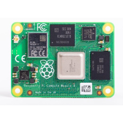
Raspberry Pi Compute Module 4 without Wi-Fi
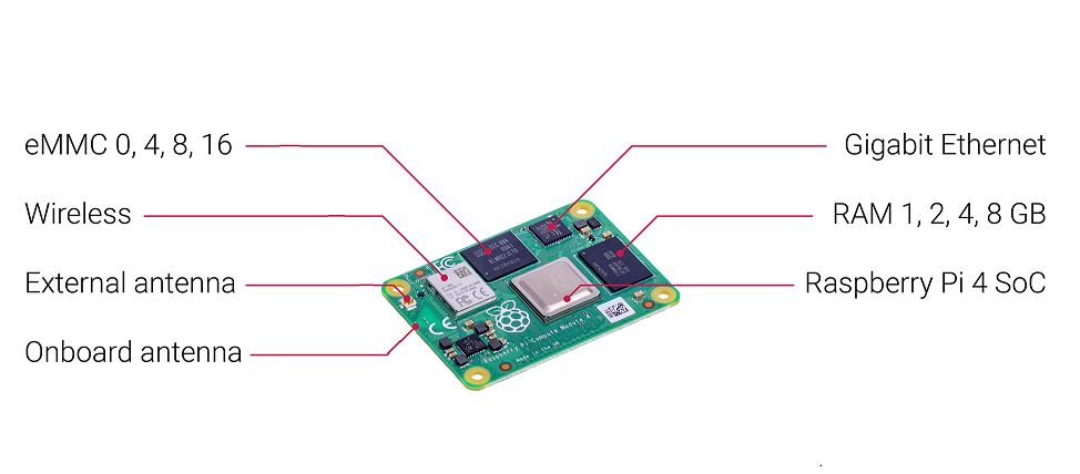
Raspberry Pi Compute Module 4 harnesses the compute power of the popular Raspberry Pi 4 Model B, bringing it to a smaller form factor suitable for integration into products. Key features include a high-performance 64-bit quad-core processor, dual-display support at resolutions up to 4K, hardware video decode at up to 4Kp60, up to 8GB of RAM, Gigabit Ethernet, USB 2.0, dual camera interfaces, and PCIe Gen 2 x1 interface. The optional dual-band 2.4/5.0GHz wireless LAN and Bluetooth 5.0 have modular compliance certification. This allows the board to be designed into end products with significantly reduced compliance testing, improving both cost and time to market. Either the onboard antenna or an external antenna kit can be used.
Compute Module 4 has optional onboard eMMC of 8GB, 16GB or 32GB.
Specifications:
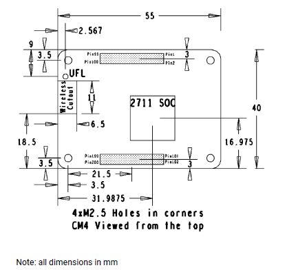
- Form factor: 55 mm × 40 mm
- Processor: Broadcom BCM2711 quad-core Cortex-A72 (ARM v8) 64-bit SoC @ 1.5GHz
- Memory: 1GB, 2GB, 4GB or 8GB LPDDR4 (depending on variant)
Connectivity:
• Optional wireless LAN, 2.4GHz and 5.0GHz IEEE 802.11b/g/n/ac wireless, Bluetooth 5.0, BLE with
onboard and external antenna options
• Onboard Gigabit Ethernet PHY supporting IEEE1588
• 1 × USB 2.0 interface
• PCIe Gen 2 x1 interface
• 28 GPIO signals
• SD card interface for SD card or external eMMC
(for use only with Compute Module 4 variants
without eMMC)
• Dual HDMI interface (up to 4Kp60 supported)
• 2-lane MIPI DSI display interface
• 2-lane MIPI CSI camera interface
• 4-lane MIPI DSI display interface
• 4-lane MIPI CSI camera interface
Multimedia:
H.265 (4Kp60 decode); H.264 (1080p60 decode, 1080p30 encode); OpenGL ES 3.0 graphics
Input power:
5V DC
Operating temperature:
0 to 80°C
Production lifetime:
Raspberry Pi Compute Module 4 will remain in production until at least January 2028
Compliance:
For a full list of local and regional product approvals, please visit
www.raspberrypi.org/documentation/hardware/raspberrypi/conformity.md
More details are available here
and a video discussion at https://www.youtube.com/watch?v=yiHgmNBOzkc&feature=youtu.be
Physical specifications
WARNINGS
• Any external power supply used with Raspberry Pi Compute Module 4 shall comply with relevant
regulations and standards applicable in the country of intended use.
• This product should be operated in a well-ventilated environment, and if used inside a case, the case should not be covered.
• Whilst in use, this product should be placed on a stable, flat, non-conductive surface, and should not be contacted by conductive items.
• The connection of incompatible devices to Compute Module 4 may affect compliance, result in damage to the unit, and invalidate the warranty.
• All peripherals used with this product should comply with relevant standards for the country of use
and be marked accordingly to ensure that safety and performance requirements are met. These
articles include but are not limited to keyboards, monitors, and mice when used in conjunction with the Compute Module.
• The cables and connectors of all peripherals used with this product must have adequate insulation so that relevant safety requirements are met.
SAFETY INSTRUCTIONS
To avoid malfunction or damage to this product, please observe the following:
• Do not expose to water or moisture, or place on a conductive surface whilst in operation.
• Do not expose to heat from any source; Raspberry Pi Compute Module 4 is designed for reliable operation at normal ambient temperatures.
• Take care whilst handling to avoid mechanical or electrical damage to the printed circuit board
and connectors.
• Whilst it is powered, avoid handling the printed circuit board, or only handle it by the edges to minimise the risk of electrostatic discharge damage.
Documents

Please note: You will need to buy a different CSI cable for use with RPi 5 or ZERO. If the Red and Blue colours are swapped on your camera, then you need to update the Pi firmware.
A camera for motion photography and machine vision
Built around Sony’s 1.6-megapixel IMX296 sensor, the Global Shutter Camera is able to capture rapid motion without introducing rolling shutter artefacts. This makes it a great fit for sports photography, and for machine vision applications, where even small amounts of distortion can seriously degrade inference performance.
Rolling shutters, global shutters
Every camera we’ve released to date, from 2014’s Camera Module 1 to our High Quality Camera and beyond, has used a rolling shutter sensor. These sensors have a two-dimensional array of light-sensitive pixels, which generate an analogue value proportional to the amount of light falling on the pixel during the exposure time; and a row of analogue-to-digital converters (ADCs), which convert these analogue values into digital values which are fed back to your Raspberry Pi.
The row of ADCs is connected to each row of the pixel array in turn, so each row is sampled at a slightly different time. Provided there is no motion in the scene this isn’t a problem, but once things start to move — and particularly if something is moving fast — we start to see rolling shutter artefacts. Linear motion results in compression, stretching, or shearing of the moving object. Rotary motion can create some very odd-looking shapes indeed.
Severe rolling shutter artefacts are unsightly, and hard to detect and correct, but even imperceptible artefacts can interfere with the operation of machine vision algorithms. If we want to eliminate them altogether, we need to use a global shutter sensor. This pairs each pixel with an analogue storage element; when the shutter fires, each pixel immediately copies its analogue value into its storage element, from where it can be read and converted at leisure.
The storage element adds complexity and area to each pixel. Global shutter sensors tend to have a lower resolution than rolling shutter sensors of the same size: contrast the 7.9mm, 12-megapixel IMX477 sensor used in the High Quality Camera with the 6.3mm, 1.6-megapixel IMX296.
Enter the Raspberry Pi Global Shutter Camera
Despite the challenges associated with rolling shutter artefacts, our existing cameras are widely used in hobbyist and industrial machine vision applications. And we’ve seen some real ingenuity: to compensate for artefacts when imaging products on a high-speed conveyor belt, one of our industrial customers ended up training their models using pre-sheared input data.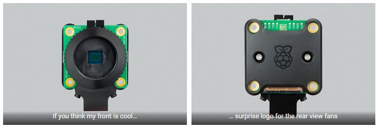
For these applications, a global shutter sensor offers clear advantages. And reduced resolution isn’t a problem, as high-resolution images are generally down-sampled before being fed into machine vision models.
The Raspberry Pi Global Shutter Camera combines the C/CS-mount metalwork of our High Quality Camera with Sony’s IMX296 sensor. It is compatible with the same broad variety of lenses, including the 6mm CS‑mount and 16mm C-mount CGL lenses that we offer through our Approved Reseller partners.
The video below illustrates the benefits of a global shutter in the presence of rapid rotary motion. First we see the output from the High Quality Camera, showing distinctive rolling shutter artefacts, and then we see the artefact-free output from the Global Shutter Camera.
Like all our camera products, you can use the Global Shutter Camera with any Raspberry Pi computer that has a CSI camera connector, and we’ve updated our hardware documentation to include everything you need to know about the new product.
You’ll need to update Raspberry Pi OS to use the new camera: sudo apt update; sudo apt full-upgrade; sudo reboot and you’re good to go.
Specifications
- Form factor: 38 × 38 × 19.8mm (29.5mm adapter and dust cap)
- Weight: 34g (41g with adapter and dust cap)
- Sensor: Sony IMX296LQR-C
- Resolution: 1.58 megapixels (colour)
- Sensor size: 6.3mm sensor diagonal
- Pixel size: 3.45μm × 3.45μm
- Output: RAW10
- Back focus length of lens: Adjustable (12.5–22.4mm)
- Lens standards: CS-Mount, C-Mount (C-CS adapter included)
- IR cut filter: Integrated
- Ribbon cable length: 150mm
- Included accessories: C-CS mount adapter, screwdriver
- Tripod mount: 1/4”-20
What's in the box?
1 x Raspberry Pi Global Shutter Camera
You might also need...
- black flexible mini tripod
- Zero mounting plate for HQ cameraa
- Pi3/4 mounting plate for HQ cameras
- 16mm telephoto lens
- 6mm wide angle camera lens
Resources
Overview
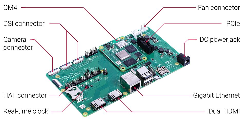
The Compute Module 4 IO Board is a companion board for Raspberry Pi Compute Module 4 (supplied separately). It is designed for use both as a development system for Compute Module 4 and as an embedded board integrated into end products.
The IO board is designed to allow you to create systems quickly using off-the shelf parts such as HATs and PCIe cards, which might include NVMe, SATA, networking, or USB. The major user connectors are located along one side to make enclosures simple.
Compute Module 4 IO Board also provides an excellent way to prototype systems using the Compute Module 4.
Specifications
• CM4 socket: suitable for all variants of Compute Module 4
• Standard Raspberry Pi HAT connectors with PoE support
• Standard PCIe Gen 2 x1 socket
• Real-time clock (RTC) with battery backup
• Dual HDMI connectors
• Dual MIPI camera connectors
• Dual MIPI display connectors
• Gigabit Ethernet socket supporting PoE HAT
• On-board USB 2.0 hub with 2 USB 2.0 connectors
• SD card socket for Compute Module 4 variants without eMMC
• Support for programming eMMC variants of Compute Module 4
• PWM fan controller with tachometer feedback
Input power: 12V input, 5V input with reduced functionality
(power supply not supplied)
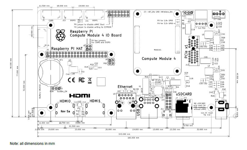
Dimensions: 160 mm × 90 mm
What's in the box?
1 x CM4 IO board
1 x Compute Module 4 board CM4004032(4GB RAM, 32GB eMMC, no wifi)
1 x 12V power supply for the board
1 x CR2032 battery for the Real-time Clock backup
1 x heatsink designed for CM4
1 x enclosure for your CM4 IO board
1 x micro B USB to USB A cable to setup/update your CM4 via rpiboot
10 x Mini Jumpers to assist you with setup
Resources
- Raspberry Pi Compute Module 4 IO Board product brief
- Raspberry Pi Compute Module 4 IO Board datasheet
- Raspberry Pi Compute Module 4 IO Board KiCAD file
Production lifetime: The Raspberry Pi Compute Module 4 IO Board will remain in production until at least January 2028
More details are available here
and a video discussion at https://www.youtube.com/watch?v=yiHgmNBOzkc&feature=youtu.be
Compliance: For a full list of local and regional product approvals,
please visit
www.raspberrypi.org/documentation/
WARNINGS
• Any external power supply used with the Raspberry Pi Compute Module 4 IO Board shall comply with relevant regulations and standards applicable in the country of intended use.
• This product should be operated in a well-ventilated environment, and if used inside a case, the case should not be covered
• Whilst in use, this product should be placed on a stable, flat, non-conductive surface, and should not be contacted by conductive items.
• The connection of incompatible devices to the Compute Module 4 IO Board may affect compliance,
result in damage to the unit, and invalidate the warranty.
• All peripherals used with this product should comply with relevant standards for the country of use and be marked accordingly to ensure that safety and performance requirements are met. These articles include but are not limited to keyboards, monitors, and mice when used in conjunction with the Compute Module 4 IO Board.
• The cables and connectors of all peripherals used with this product must have adequate insulation so that relevant safety requirements are met.
SAFETY INSTRUCTIONS
To avoid malfunction or damage to this product, please observe the following:
• Do not expose to water or moisture, or place on a conductive surface whilst in operation.
• Do not expose to heat from any source; the Raspberry Pi Compute Module 4 IO Board is designed for reliable operation at normal ambient temperatures.
• Take care whilst handling to avoid mechanical or electrical damage to the printed circuit board
and connectors.
• Whilst it is powered, avoid handling the printed
Overview
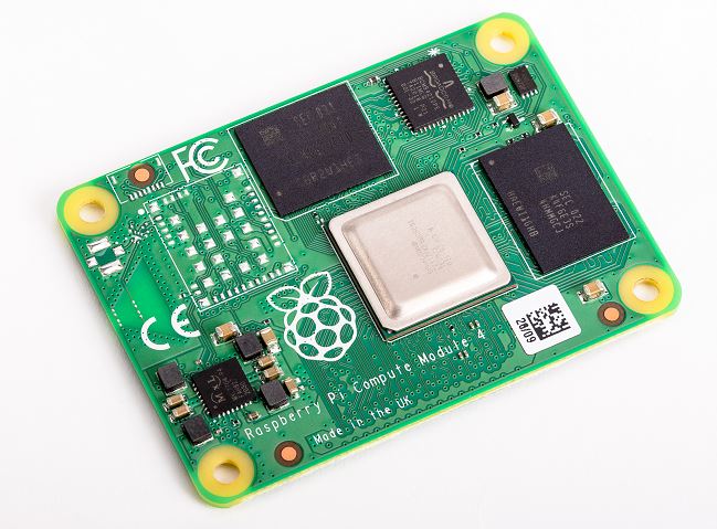
Raspberry Pi Compute Module 4 with Wi-Fi
Raspberry Pi Compute Module 4 harnesses the compute power of the popular Raspberry Pi 4 Model B, bringing it to a smaller form factor suitable for integration into products. Key features include a high-performance 64-bit quad-core processor, dual-display support at resolutions up to 4K, hardware video decode at up to 4Kp60, up to 8GB of RAM, Gigabit Ethernet, USB 2.0, dual camera interfaces, and PCIe Gen 2 x1 interface. The optional dual-band 2.4/5.0GHz wireless LAN and Bluetooth 5.0 have modular compliance certification. This allows the board to be designed into end products with significantly reduced compliance testing, improving both cost and time to market. Either the onboard antenna or an external antenna kit can be used.
Compute Module 4 has optional onboard eMMC of 8GB, 16GB or 32GB.
Specifications
- Form factor: 55 mm × 40 mm
- Processor: Broadcom BCM2711 quad-core Cortex-A72 (ARM v8) 64-bit SoC @ 1.5GHz
- Memory: 1GB, 2GB, 4GB or 8GB LPDDR4 (depending on variant)
Connectivity
• Optional wireless LAN, 2.4GHz and 5.0GHz IEEE 802.11b/g/n/ac wireless, Bluetooth 5.0, BLE with
onboard and external antenna options
• Onboard Gigabit Ethernet PHY supporting IEEE1588
• 1 × USB 2.0 interface
• PCIe Gen 2 x1 interface
• 28 GPIO signals
• SD card interface for SD card or external eMMC
(for use only with Compute Module 4 variants
without eMMC)
• Dual HDMI interface (up to 4Kp60 supported)
• 2-lane MIPI DSI display interface
• 2-lane MIPI CSI camera interface
• 4-lane MIPI DSI display interface
• 4-lane MIPI CSI camera interface
Multimedia
H.265 (4Kp60 decode); H.264 (1080p60 decode, 1080p30 encode); OpenGL ES 3.0 graphics
Input power
5V DC
Operating temperature
0 to 80°C
Production lifetime
Raspberry Pi Compute Module 4 will remain in production until at least January 2028
Compliance
For a full list of local and regional product approvals, please visit
www.raspberrypi.org/documentation/hardware/raspberrypi/conformity.md
More details are available here
and a video discussion at https://www.youtube.com/watch?v=yiHgmNBOzkc&feature=youtu.be
Physical specifications
What's in the box?
1 x CM4 board
Have a look at the rest of our industrial related range
Resources
- Raspberry Pi Compute Module 4 product brief
- Raspberry Pi Compute Module 4 datasheet
- Compute Module 4 STEP file
- Compute Module 4 Lite (without eMMC) STEP file
WARNINGS
• Any external power supply used with Raspberry Pi Compute Module 4 shall comply with relevant
regulations and standards applicable in the country of intended use.
• This product should be operated in a well-ventilated environment, and if used inside a case, the case should not be covered.
• Whilst in use, this product should be placed on a stable, flat, non-conductive surface, and should not be contacted by conductive items.
• The connection of incompatible devices to Compute Module 4 may affect compliance, result in damage to the unit, and invalidate the warranty.
• All peripherals used with this product should comply with relevant standards for the country of use
and be marked accordingly to ensure that safety and performance requirements are met. These
articles include but are not limited to keyboards, monitors, and mice when used in conjunction with the Compute Module.
• The cables and connectors of all peripherals used with this product must have adequate insulation so that relevant safety requirements are met.
SAFETY INSTRUCTIONS
To avoid malfunction or damage to this product, please observe the following:
• Do not expose to water or moisture, or place on a conductive surface whilst in operation.
• Do not expose to heat from any source; Raspberry Pi Compute Module 4 is designed for reliable operation at normal ambient temperatures.
• Take care whilst handling to avoid mechanical or electrical damage to the printed circuit board
and connectors.
• Whilst it is powered, avoid handling the printed circuit board, or only handle it by the edges to minimise the risk of electrostatic discharge damage.

Overview
The Compute Module 4 IO Board is a companion board for Raspberry Pi Compute Module 4 (supplied separately). It is designed for use both as a development system for Compute Module 4 and as an embedded board integrated into end products.
The IO board is designed to allow you to create systems quickly using off-the shelf parts such as HATs and PCIe cards, which might include NVMe, SATA, networking, or USB. The major user connectors are located along one side to make enclosures simple.
Compute Module 4 IO Board also provides an excellent way to prototype systems using the Compute Module 4.
Specifications
• CM4 socket: suitable for all variants of Compute Module 4
• Standard Raspberry Pi HAT connectors with PoE support
• Standard PCIe Gen 2 x1 socket
• Real-time clock (RTC) with battery backup
• Dual HDMI connectors
• Dual MIPI camera connectors
• Dual MIPI display connectors
• Gigabit Ethernet socket supporting PoE HAT
• On-board USB 2.0 hub with 2 USB 2.0 connectors
• SD card socket for Compute Module 4 variants without eMMC
• Support for programming eMMC variants of Compute Module 4
• PWM fan controller with tachometer feedback
Input power: 12V input, 5V input with reduced functionality
(power supply not supplied)
Dimensions: 160 mm × 90 mm
What's in the box?
1 x CM4 IO board
1 x Compute Module 4 board CM4101032
1 x 12V power supply for the board
1 x CR2032 battery for the Real-time Clock backup
1 x heatsink designed for CM4
1 x enclosure for your CM4 IO board
1 x micro B USB to USB A cable to setup/update your CM4 via rpiboot
1 x antenna kit if your CM4 has onboard wifi
10 x Mini Jumpers to assist you with setup
Resources
- Raspberry Pi Compute Module 4 IO Board product brief
- Raspberry Pi Compute Module 4 IO Board datasheet
- Raspberry Pi Compute Module 4 IO Board KiCAD file
Production lifetime: The Raspberry Pi Compute Module 4 IO Board will remain in production until at least January 2028
More details are available here
and a video discussion at https://www.youtube.com/watch?v=yiHgmNBOzkc&feature=youtu.be
Compliance: For a full list of local and regional product approvals,
please visit
www.raspberrypi.org/documentation/
WARNINGS
• Any external power supply used with the Raspberry Pi Compute Module 4 IO Board shall comply with relevant regulations and standards applicable in the country of intended use.
• This product should be operated in a well-ventilated environment, and if used inside a case, the case should not be covered
• Whilst in use, this product should be placed on a stable, flat, non-conductive surface, and should not be contacted by conductive items.
• The connection of incompatible devices to the Compute Module 4 IO Board may affect compliance,
result in damage to the unit, and invalidate the warranty.
• All peripherals used with this product should comply with relevant standards for the country of use and be marked accordingly to ensure that safety and performance requirements are met. These articles include but are not limited to keyboards, monitors, and mice when used in conjunction with the Compute Module 4 IO Board.
• The cables and connectors of all peripherals used with this product must have adequate insulation so that relevant safety requirements are met.
SAFETY INSTRUCTIONS
To avoid malfunction or damage to this product, please observe the following:
• Do not expose to water or moisture, or place on a conductive surface whilst in operation.
• Do not expose to heat from any source; the Raspberry Pi Compute Module 4 IO Board is designed for reliable operation at normal ambient temperatures.
• Take care whilst handling to avoid mechanical or electrical damage to the printed circuit board
and connectors.
• Whilst it is powered, avoid handling the printed
Overview
Raspberry Pi Compute Module 4 with Wi-Fi
Raspberry Pi Compute Module 4 harnesses the compute power of the popular Raspberry Pi 4 Model B, bringing it to a smaller form factor suitable for integration into products. Key features include a high-performance 64-bit quad-core processor, dual-display support at resolutions up to 4K, hardware video decode at up to 4Kp60, up to 8GB of RAM, Gigabit Ethernet, USB 2.0, dual camera interfaces, and PCIe Gen 2 x1 interface. The optional dual-band 2.4/5.0GHz wireless LAN and Bluetooth 5.0 have modular compliance certification. This allows the board to be designed into end products with significantly reduced compliance testing, improving both cost and time to market. Either the onboard antenna or an external antenna kit can be used.
Compute Module 4 has optional onboard eMMC of 8GB, 16GB or 32GB.
Specifications:
- Form factor: 55 mm × 40 mm
- Processor: Broadcom BCM2711 quad-core Cortex-A72 (ARM v8) 64-bit SoC @ 1.5GHz
- Memory: 1GB, 2GB, 4GB or 8GB LPDDR4 (depending on variant)
Connectivity:
• Optional wireless LAN, 2.4GHz and 5.0GHz IEEE 802.11b/g/n/ac wireless, Bluetooth 5.0, BLE with
onboard and external antenna options
• Onboard Gigabit Ethernet PHY supporting IEEE1588
• 1 × USB 2.0 interface
• PCIe Gen 2 x1 interface
• 28 GPIO signals
• SD card interface for SD card or external eMMC
(for use only with Compute Module 4 variants
without eMMC)
Video:
• Dual HDMI interface (up to 4Kp60 supported)
• 2-lane MIPI DSI display interface
• 2-lane MIPI CSI camera interface
• 4-lane MIPI DSI display interface
• 4-lane MIPI CSI camera interface
Multimedia:
H.265 (4Kp60 decode); H.264 (1080p60 decode, 1080p30 encode); OpenGL ES 3.0 graphics
Input power:
5V DC
Operating temperature:
0 to 80°C
Production lifetime:
Raspberry Pi Compute Module 4 will remain in production until at least January 2028
Compliance:
For a full list of local and regional product approvals, please visit
www.raspberrypi.org/documentation/hardware/raspberrypi/conformity.md
More details are available here
and a video discussion at https://www.youtube.com/watch?v=yiHgmNBOzkc&feature=youtu.be
Physical specifications
WARNINGS
• Any external power supply used with Raspberry Pi Compute Module 4 shall comply with relevant
regulations and standards applicable in the country of intended use.
• This product should be operated in a well-ventilated environment, and if used inside a case, the case should not be covered.
• Whilst in use, this product should be placed on a stable, flat, non-conductive surface, and should not be contacted by conductive items.
• The connection of incompatible devices to Compute Module 4 may affect compliance, result in damage to the unit, and invalidate the warranty.
• All peripherals used with this product should comply with relevant standards for the country of use
and be marked accordingly to ensure that safety and performance requirements are met. These
articles include but are not limited to keyboards, monitors, and mice when used in conjunction with the Compute Module.
• The cables and connectors of all peripherals used with this product must have adequate insulation so that relevant safety requirements are met.
SAFETY INSTRUCTIONS
To avoid malfunction or damage to this product, please observe the following:
• Do not expose to water or moisture, or place on a conductive surface whilst in operation.
• Do not expose to heat from any source; Raspberry Pi Compute Module 4 is designed for reliable operation at normal ambient temperatures.
• Take care whilst handling to avoid mechanical or electrical damage to the printed circuit board
and connectors.
• Whilst it is powered, avoid handling the printed circuit board, or only handle it by the edges to minimise the risk of electrostatic discharge damage.
Documents
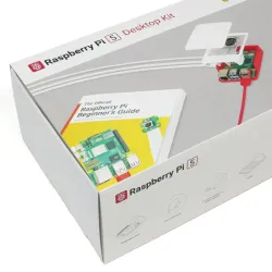
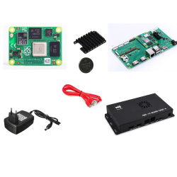
The Raspberry Pi 5 desktop kit offers a compact and powerful computing solution. Featuring the latest Raspberry Pi model, it includes all essential peripherals for seamless desktop use. With enhanced performance and versatility, this kit is perfect for DIY enthusiasts, educators, and professionals alike, enabling a wide range of projects from coding to media streaming and beyond.
What's in the box?
1 x Raspberry Pi 8GB board
1 x Official Raspberry Pi 5 Case(red/white) - Includes heatsink and fan
1 x Official 27W USB-C PD Power Supply(white)
1 x Official Keyboard(red/white)
1 x Official Mouse(red/white)
1 x 32GB SD card with Raspberry OS Bookworm
2 x Official micro-HDMI cables(white)
1 x The fifth edition of the Raspberry Pi Beginner’s Guide
Just add a HDMI monitor
You will also need a euro plug adapter
Resources