Special Offers

Features
Flashed with CC2531ZNP-Prod firmware for zigbee2mqtt application Lead out 8 IO connectors Debug interface Size: 5.6*1.6*0.7cm Two buttons and two LEDs for user interaction.
What's in the box?
1 x Sonoff Zigbee dongle

https://youtu.be/X6qFEwy2X2w
New to Mobile Robot & Coding?
Don't worry! This kit comes with a booklet covering all the hands-on lessons you need to get started. Every step is explained clearly with the help of images. We make sure that the common issues when building and coding the Arduino mobile robot are properly addressed in this booklet. Besides it comes with fun facts to feed the curious minds too.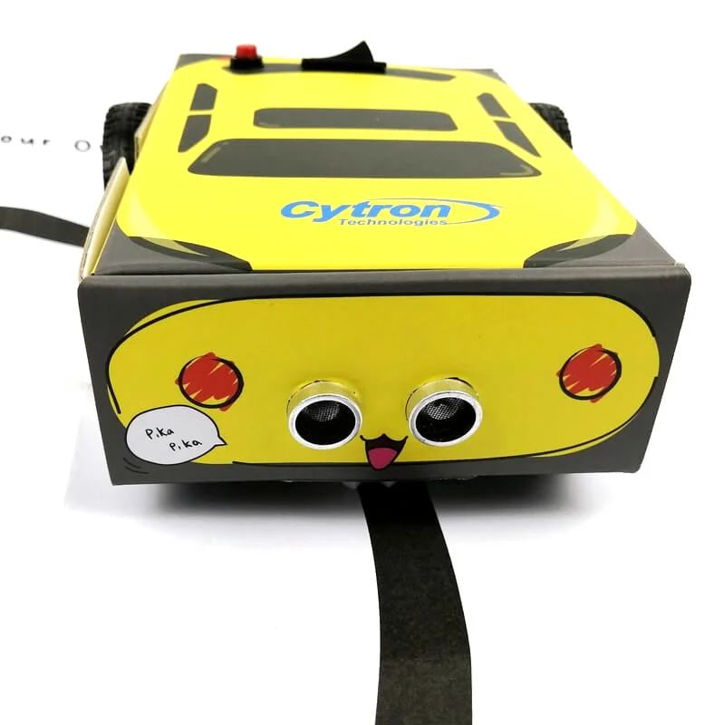
No Soldering! Just Jumper Wires
There is no soldering involved in order for more young makers to take part in the building process. To make things even simpler, the detailed schematic diagram and mounting location of the parts are printed inside the box. Hence you can build and connect with greater confidence as you embark on this digital making journey.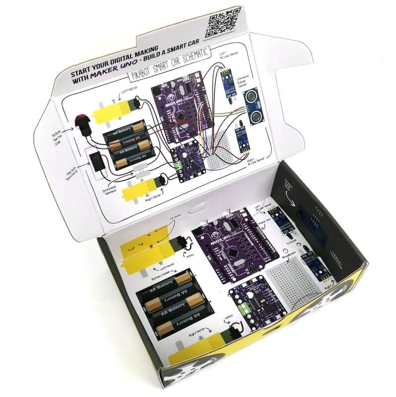
This mobile robot kit is based on Maker UNO (Arduino Uno compatible).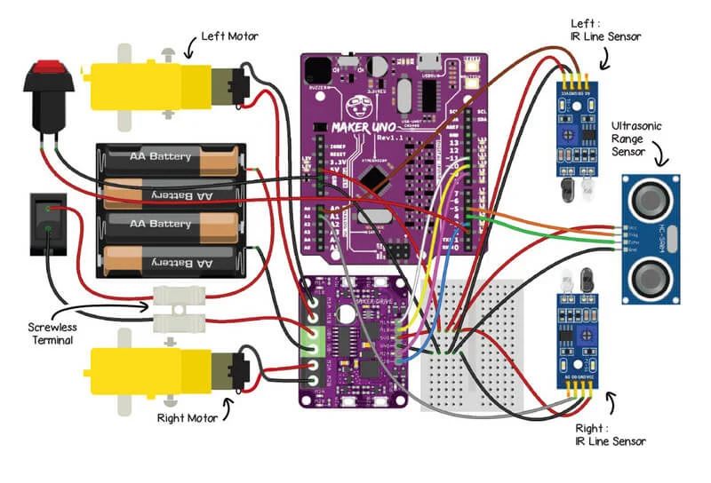
Box = Mobile Robot Base
We designed the packaging box of PikaBot to be reusable. Not only that it's used for packing the complete set of components needed for the project, it serves as the robot base and cover of your PikaBot mobile robot too.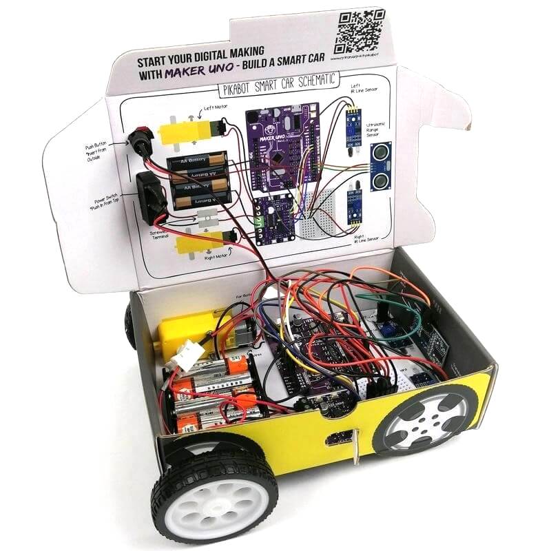
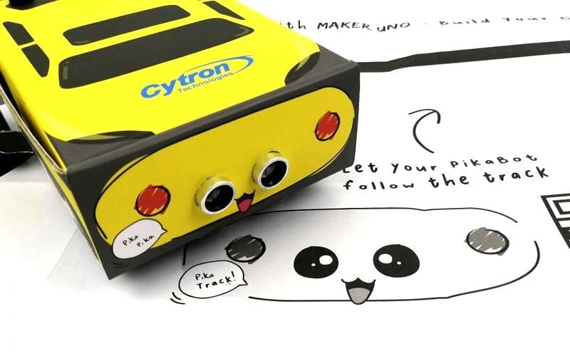
Line Following & Obstacle Avoidance
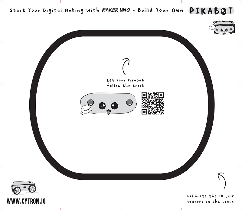
What can your PikaBot do? It can follow line, simple yet practical navigation that is widely used in AGV (Automated Guided Vehicle) and many robot competition. The kit comes with a pair of infrared sensors which you can calibrate & program to recognize black and white surfaces. PikaBot also includes an ultrasonic distance sensor so it can detect obstacles in front of it.
mBlock Graphical Programming Interface
Besides using the Arduino IDE as taught in our user guide booklet, you can also program PikaBot with mBlock block-based programmming interface. Check out this tutorial to learn more.
https://youtu.be/S-xbk-PoiWY
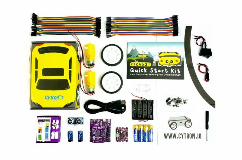
With the beginner-friendly Maker UNO as the controller, everyone can build and program this mobile robot. We have also included
- Dual-channel motor driver - Maker Drive
- Two "TT" brush motor with pre-solder wires
- 4 x AA battery to power the controller and motor
- Of course, it comes with two IR Line Tracking Module for line following
- An Ultrasonic Distance Sensor for obstacle avoidance
- Accessories for the smart car to work :)
- Everything is packed in a nicely designed paper box which will be utilized as the base of the mobile robot too
To make life even easier, we have prepared:
- A printed copy of Step by Step Guide for you to build this kit (Softcopy here)
- Sample code for line following, obstacle avoidance and melody in Arduino Sketch in Github (coming soon)
- Video to assemble the robot is in the making, check it out
Line Following Track for line following.
Features
- Mobile Robot Kit
- Do It Yourself (DIY) mobile robot kit
- No soldering needed, only requires to connect jumper wires :)
- Controller: Maker UNO
- Motor Driver: Maker Drive dual-channel DC brush motor driver
- Driven by two TT motor with pre-solder wires
- Power both controller and motor with 4 x AA battery, with battery holder too
- Comes with IR Line Sensor module, for line following
- Open-source example code, free to modify and learn coding
- Panel mount rocker switch as power activation switch
- Panel mount push button as a start button
- The paper box is creatively designed as the container and also body for mobile robot.
- Everything needed is packed in this kit!
- Box Dimension: 127mm x 55mm x 19mm (not including motor shafts and wheels)
What's in the box?
1 x Maker Drive: Dual H-Bridge Motor Driver for Beginner
2 x 3 - 6VDC Dual Axis TT Gear Motor (with pre-solder wires)
2 x Rubber Wheel for TT Gear Motor (63mm x 15mm)
2 x IR Line Tracking Module
1 x HC-SR04 Ultrasonic Ranging Module
1 x 4xAA Batteries
1 x 4xAA battery holder
1 x Breadboard Mini (35mmx42mm) - White
1 x 40 ways Male to Female Jumper Wire
1 x 40 ways Male to Male Jumper Wire
1 x USB Micro B cable
1 x mBot N20 Vacuum Steel Ball Castor
1 x Tiny Phillips Screwdriver - 85mm
4 x Bolt M3x25mm
4 x M3 Nut
1 x CH2 Quick Wiring Terminal Press Type
1 x Rocker Switch with wires
1 x Push Button with wires
14 x Plastic Rivet (M3)
2 x Plastic Rivet (M4)
1 x PikaBot Track
1 x PikaBot Booklet - A step-by-step guide to build & program PikaBot.
1 x PikaBot Paper Box
Resources
- Softcopy (PDF) of PikaBot Booklet (Hardcopy comes with the kit)
- Arduino sample code
- PikaBot is now programmable with mBlock, a tutorial on Hackster.io. Now you can use block(graphical) programming to program PikaBot.
- CH34X driver (Please ensure the Maker UNO is plug into computer USB port during driver installation)
- Windows (V3.5 Mar2019)
- Mac OS (V1.5 Mar2019)
- Linux (V1.5 Mar2019) (Normally is readily installed)
- CH34X Driver - Get the latest driver from the factory
- Arduino IDE Download
Telegram Stickers!
Last but not least, we've designed some expressive PikaBot stickers for Telegram messenger for all you PikaBot lovers! If you are a Telegram user, grab the sticker pack here: https://t.me/addstickers/cytron_pikabot. Have fun!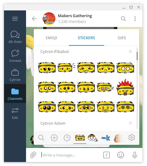

1. Most of the students do not have basic knowledge in electronics.
2. They do not understand the circuit diagram at the beginning of the Arduino lesson. They will spend a substantial amount of time just to connect the wires and troubleshoot the connections.
3. It's a mess after every class. The teacher has to sort and make sure nothing is missing. What a tedious job and a waste of time!
Students can skip the hassle of constructing the basic electronic circuit which is boring and time consuming. Although it is equally important for them to learn about basic electronics, it can always come later after they have experienced how easy it is to create awesome project. Start with fun and excitement. Start coding right away and see your board lights up and plays melody with the press of a button. 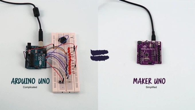
With the conventional Arduino boards, students also face another common problem - difficulty in troubleshooting their circuit. This is because when it doesn't work, we do not know whether the problem is due to wire connection or coding.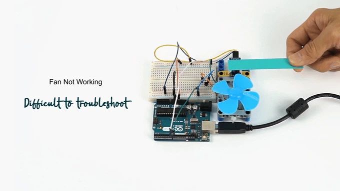
With Maker UNO, the problem is solved! Not only do the onboard LEDs work as outputs, they can also act as indicators, clearly showing what's happening on that pin. When the pin is used as input, you can clearly see whether the signal is received by just looking at changes on the LEDs. 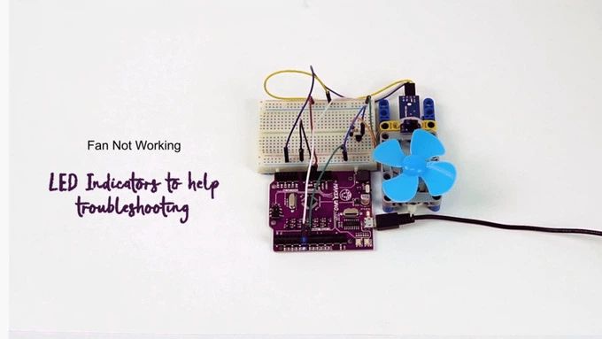
Additional Features
One of the brilliant features of the official Arduino Uno is the label printed on its pin headers. It saves us a lot of time when we want to connect the I/O pins to the external circuit. So, we include a set of these label stickers for pin headers in each of the Maker UNO! (Please note that you need to peel off the stickers and stick them on your Maker UNO by yourself)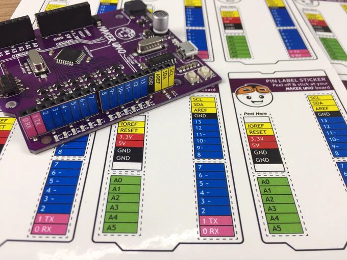
Students always get their boards mixed up. With Maker UNO, you can write your name on the board. Problem solved!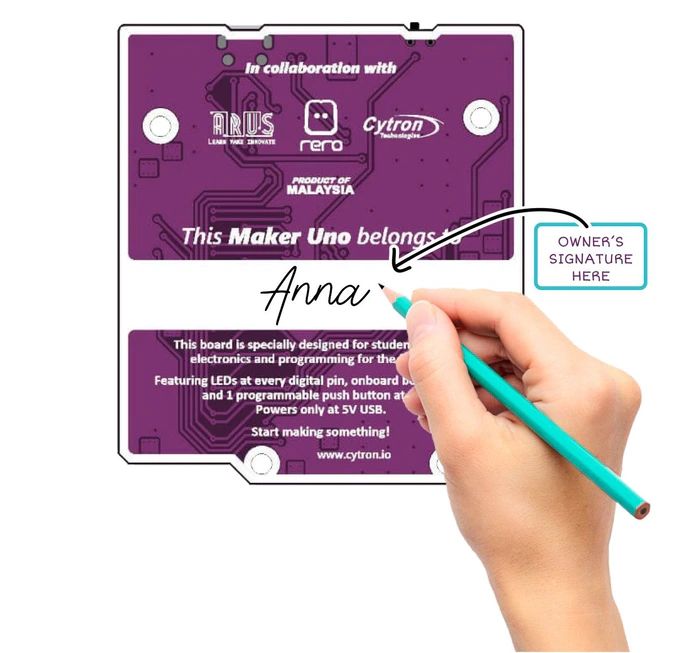
Maker UNO uses the common Micro USB cable which is basically everywhere.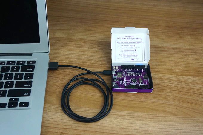
Don't throw your box away! There is a small opening on the box for you to plug the USB cable so that you can keep your Maker UNO safely in the original box, no additional casing required.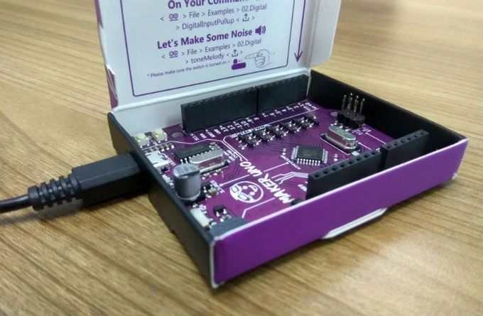
Specifications
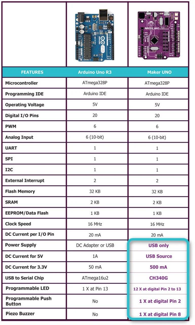
Maker UNO is fully compatible with Arduino. You can share the same library and code. We put in 12x LEDs, 1x piezo buzzer and 1x programmable button on the Maker UNO. We have removed the DC jack power input socket as most of the boards used in classes are powered using USB. We have also replaced the ATmega16u2 with CH340 to bring down the cost.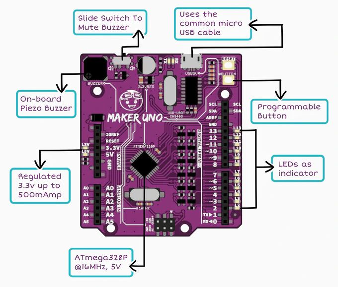
Documents:
- Maker UNO User's Manual
- Maker UNO Edu Kit Getting Started Module
- Maker-UNO Schematic
- Maker-UNO Fritzing File
- CH341 driver
Tutorials:
Related links:
- Maker UNO's Default Program
- Arduino IDE Download
- How To Program Arduino (Maker UNO) Using Atmel Studio
- Introduction Atmel Studio 7 is the integrated development platform (IDP) for developing and debugging all AVR® and SAM microcontroller applications. The Atmel Studio 7 IDP gives you a seamless and easy-to-use environment to write, build and debug your applications written in C/C or assembly code.
- Program Maker UNO using Chromebook

The Typical Problem Faced by Beginners in Learning Electronics on Raspberry Pi
- Hard to get started without additional devices (monitor, keyboard, and mouse). Beginners will either need to use additional devices or follow many steps just to get started. This may confuse them. For techies that want to know why, this is because it lacks an onboard USB to UART communication for your computer to get the IP address for SSH (headless), or to kick start configuration directly.
- Hard to get started with electronics. It doesn't come with any inputs or outputs, you will need to connect additional accessories to use it. Most beginners do not have basic knowledge of electronics. They will have a problem to understand the circuit diagram and connections needed when they first started learning. They will spend a substantial amount of time just to connect the wires and troubleshoot the connections.
- Hard to troubleshoot the GPIO. With just the raspberry pi, beginners face a common problem when learning electronics- difficulty in troubleshooting their circuit. This is because when it doesn't work, we do not know whether the problem is due to wire connection or coding.
- Access to GPIO is kind of difficult. There is no label on the pins, you need to search online to get the designated pin and know which pin to connect. For beginners, this definitely will make it harder for them to make the connection correctly.
- No easy way to properly shutdown using a switch. There is no programmable push button to enable proper shutdown through hardware. If the beginner turns off the power without properly shutting it down, the raspberry pi may not work the next time.
Introducing Our Solution: Maker pHAT
Maker pHAT solves all these. It is designed to:
- Simplify to get started with Raspberry Pi without additional monitor, keyboard or mouse (Headless). Go headless with a few simple steps as it enables users to remote access Raspberry Pi through serial.
- Simplify learning electronics. Beginners can skip the hassle of constructing the basic electronic circuit which is boring and time-consuming. Although it is equally important for them to learn about basic electronics, it can always come later after they have experienced how easy it is to create an awesome project. Start with fun and excitement. Start coding right away and see your board lights up and plays sound with the press of a button. It comes with onboard LEDs, pushbuttons, and a buzzer to easily learn how to control input and output. No messy wiring needed and no additional components needed.
- Simplify troubleshooting and prototyping. Not only do the onboard LEDs work as outputs, but they can also act as indicators, clearly showing what's happening on that pin. When the pin is used as input, you can clearly see whether the signal is received by just looking at changes on the LEDs. The pre-soldered header pins come with nice labels. This helps the user to easily connect inputs and outputs to the right pins. This will further assist them in interfacing with sensors and actuators.
- Simplify proper shutdown using pushbutton. You can easily follow the steps and choose one of the pushbuttons as the power button to properly shutdown the Raspberry Pi. Just press the button and it will shut down.
Video: https://youtu.be/EJWxLi7fLSo
Maker pHAT for Raspberry Pi
Maker pHAT is designed to be the same size as Raspberry Pi Zero board, it stacks perfectly on top of Rpi Zero with the four mounting holes aligned. (What is a HAT? Read this to know more) We do advise getting Raspberry Pi Zero WH (pre-solder header pin) for beginner because it is not an easy work to solder the 40-pin GPIO, don't forget you'll need to have the soldering tools too.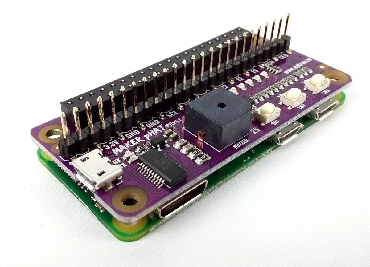
Maker pHAT is also compatible with Raspberry Pi 3B, 3B , 3A , and of course the latest 4B too. You just need to insert the 2x20 stacking header(included), as photo shows: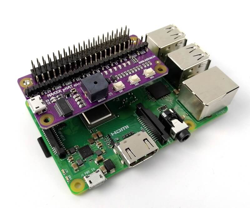
Maker pHAT is compatible with:
- Raspberry Pi Zero V1.3 (will need to solder 2x20 header pin - NOT included can consider Straight Pin Header (Male) 2x40 Ways)
- Raspberry Pi Zero W (will need to solder 2x20 header pin - NOT included can consider Straight Pin Header (Male) 2x40 Ways)
- Raspberry Pi Zero WH (Ready for plug and use)
- Raspberry Pi 1 https://www.pishop.co.za/store/raspberry-pi-model-aModel A (Will need 2x20 stacking header)
- Raspberry Pi 3 Model A (Will need 2x20 stacking header)
- Raspberry Pi 3 Model B (Will need 2x20 stacking header)
- Raspberry Pi 3 Model B (Will need 2x20 stacking header)
- Raspberry Pi 4 Model B 1GB (Will need 2x20 stacking header)
- Raspberry Pi 4 Model B 2GB (Will need 2x20 stacking header)
- Raspberry Pi 4 Model B 4GB (Will need 2x20 stacking header)
Features:
- Raspberry Pi Zero size, stack perfectly on to Pi Zero Series of SBC (Single Board Computer).
- Compatible with standard size Raspberry Pi 3B/3B /4B1GB/4B2GB/4B4GB, medium size Raspberry Pi 3A and smaller size Raspberry Pi Zero/W/WH.
- Standard Raspberry Pi GPIO footprint.
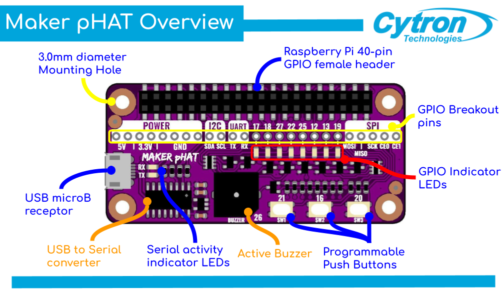
- LED array for selected GPIO pins (GPIO 17, 18, 27, 22, 25, 12, 13, 19).
- 3x onboard programmable push buttons (GPIO 21, 19 and 20, need to configure as input pull up).
- Onboard active buzzer (GPIO 26).
- Proper label for all GPIOs, including SPI, UART, I2C, 5V, 3.3V, and GND.
- Utilize USB Micro-B socket for 5V input and USB to UART communication.
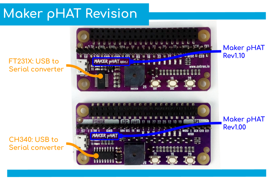
- USB serial facilitated by the CH340, Rev1.10 uses FT231X as the USB to UART
- Input voltage: USB 5V, from the computer, power bank or standard USB adapter.
- PURPLE PCB!
Documents/Tutorials:
- User's Manual
- Schematic Rev1.00 (pdf)
- Schematic Rev1.10 (pdf)
- Sample Python Code (Github)
- CH340 Driver (Windows)
- CH340 Driver (MacOS)
- CH340 Driver (Linux) - Pre-installed
- FT231X Driver on Rev1.10 (Windows, Linux, and macOS)
- PuTTY - For serial terminal
- Raspberry Pi: Mengawal LED di Maker pHAT
Packing List:
- 1 x Maker pHAT
- 1 x 2x20 Stacking Header

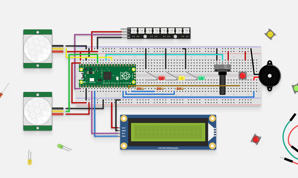
Basic entry-level kit prepared for Pico. All the parts you need to complete the tutorials in the MicroPython beginners book (not included)
Tested and selected by professional engineer, with rich tutorials and resources
fast getting started with Raspberry Pi Pico and MicroPython programming
A Low-Cost, High-Performance Microcontroller Board With Flexible Digital Interfaces
- RP2040 microcontroller chip designed by Raspberry Pi in the United Kingdom
- Dual-core Arm Cortex M0 processor, flexible clock running up to 133 MHz
- 264KB of SRAM, and 2MB of on-board Flash memory
- Castellated module allows soldering direct to carrier boards
- USB 1.1 with device and host support
- Low-power sleep and dormant modes
- Drag-and-drop programming using mass storage over USB
- 26 × multi-function GPIO pins
- 2 × SPI, 2 × I2C, 2 × UART, 3 x12-bit ADC, 16 × controllable PWM channels
- Accurate clock and timer on-chip
- Temperature sensor
- Accelerated floating-point libraries on-chip
- 8 × Programmable I/O (PIO) state machines for custom peripheral support
| Item | Description |
|---|---|
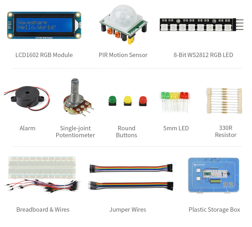
| LCD1602 RGB Module | LCD1602 RGB backlight character LCD, using I2C bus to display text or adjust RGB backlight |
| PIR motion sensor | Pyroelectric IR sensor, outputs electric switch signal when IR array from human/animal body is detected |
| 8-Bit WS2812 RGB LED | 8x RGB LED, play around with cool light effects by programming |
| Alarm | Quality active announciator, used for alarming or playing music |
| Single-joint potentiometer | Adjustable potentiometer, 0~10K range, used for ADC test, volume/brightness adjustment, etc. |
| Round buttons | Three colors, for button/switch detection |
| 5mm LED | Three colors, for experiments like traffic light, PWM adjusted light, etc. |
| 330R resistors | Providing current-limit protection when connected with LED in series |
| Breadboard and wires Jumper wires | Quality 830 breadboard and sorts of wires, easy for connecting components |
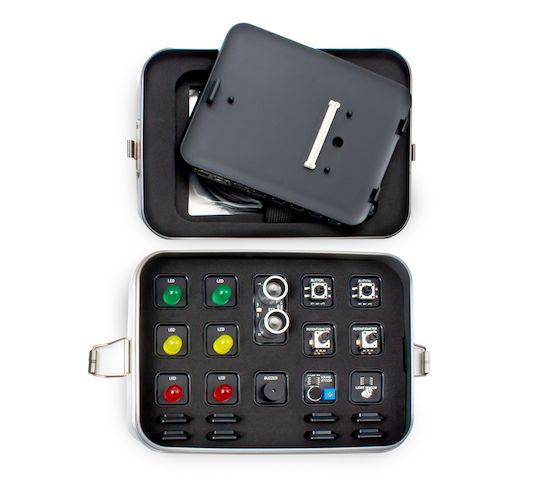
| Plastic box | Customized box for storing the modules and components |

Built especially to showcase the low cost, feature-rich RP2040 chip on the Raspberry Pi Pico, this board has VGA output, an SD card slot, digital I2S audio output, and more!
Based on the reference design by Raspberry Pi, our Pimoroni Pico VGA Demo Base is a great way to start experimenting with Raspberry Pi Pico/RP2040. It's the perfect way to demo of some of the fun things you can achieve with the RP2040 microcontroller such as generating a solid VGA output without taxing the CPU at all!
- Amaze your friends by showing them you still own a D-sub cable!
- Bask in the glory of 15-bit analog video!
- Get teary eyed over the warm, authentic, RC filtered PWM audio!
This board will run the various video example programs that Raspberry Pi have put together to demonstrate features of the RP2040.
Please note that VGA Demo Base only currently works with the C/C Pico SDK!
A Raspberry Pi Pico is not included - click here if you'd like to buy one!
Your Pico will need to have male headers soldered to it (with the pins pointing downwards) to attach to our add-on boards.
Features
- 15-pin VGA (D-sub) connector
- PCM5100A DAC for line out audio over I2S (datasheet)
- PWM audio output
- SD card slot
- Reset button
- Female headers to install your Raspberry Pi Pico
- Three user-controllable switches
- Rubber feet
- Compatible with Raspberry Pi Pico
- No soldering required (as long as your Pico has header pins attached)
- Programmable with C/C
What's in the box?
1 x Pimoroni Pico VGA Demo Base
Resources
Getting started
The pin-out of our board is the same as Raspberry Pi's reference board, you can find it in chapter 3 of Hardware Design with RP2040 along with more general info about the VGA reference board.
To run the audio and video examples in Raspberry Pi's experimental repos, first make sure you have up to date versions of pico-extras and pico-playground. When building the examples, you will need to specify the board configuration so that the examples use the correct pins. You can do this by creating a new build directory and then specifying the board definition when using cmake:
cmake -D"PICO_BOARD=vgaboard" ..
There's more details on about how to build applications with custom board configurations in Appendix D / page 267 of the C/C SDK documentation.
Pinout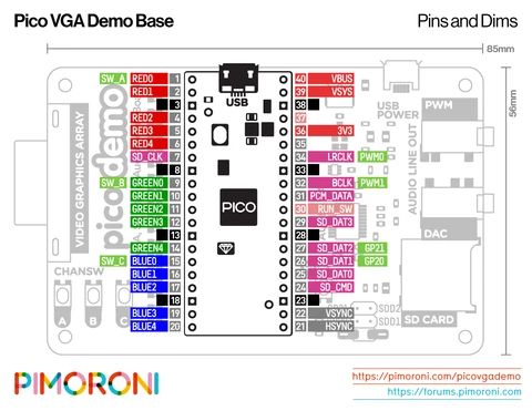

Compared with traditional ultrasonic modules HC-SR04, this module integrates a single-chip microcomputer, and the transmitting signal and the receiving signal share one pin by time division multiplexing, so only one I/O pin is occupied. Another difference is that HC-SR04 only supports 5V voltage, while this module supports 5V and 3.3V. As we know, the Raspberry pi I/O only supports 3.3V. Therefore, this Grove - Ultrasonic Distance Sensor can be directly connected to the I/O of the Raspberry Pi, but HC-SR04 needs to use a voltage conversion circuit.
- 3.3V / 5V compatible, wide voltage level: 3.2V~5.2V
- Only 3 pins needed, save I/O resources
- Wide measurement range: 3cm ~ 350cm
- Easy to use: grove connector, plug and play
- Arduino library ready
Specifications
- Operating Voltage: 3.2~5.2V
- Operating Current: 8mA
- Ultrasonic Frequency: 40kHz
- Measuring Range: 3cm to 350cm
- Resolution: 1cm
- Measurement Angle: 15 degree
- Dimensions: 50mm x 25mm x 16mm
What's in the box?
1 x Grove - Ultrasonic Ranger1 x Grove 4 Pin Buckled 20cm Cable
Resources
- Grove - Introduction to Grove
- Grove - Ultrasonic Ranger interface with Arduino and Raspberry pi by wiki.seeedstudio
- Grove - Ultrasonic Ranger schematic
- Grove - Ultrasonic Ranger library
- CDC file

Features
- Automatically sleep after 10 minutes.
- Automatically shut down after 20 minutes.
- Temperature reach 480°C in 1 minute.Build in PID system equipped.
- 9 shortcut range to adjust temperature by button
- Products use LCD display
Specifications
- Voltage: AC220V
- Temperature range:250~480°C
- Temperature stability:±1°C
- Temperature offset range:±10°C
- Temperature Unit:°C/℉
- Heater: Four-core PTC ceramic heater
- Power - Model Number:65W -ST-2065D
- Colour:black
- Material:ABS metal
- Size:25*2*3cm
What's in the box?
1 x ATTEN ST-2065D Soldering Iron

- Designed with nixie tube display.
- MCU controlled temperature calibration with PID system equipped, adjustable
- Temperature selection using knob, easy to operate.
- Combined soldering station with soldering stand.
- The handle structure is ergonomically designed for comfortable grip.
- The heating wire and sensor are made of PTC material, which is quick in
- Temperature rise and precise in temperature control.
Specifications
- Voltage: 110/220 VAC
- Power: 80W
- Temp Range 80°C ~ 480°C
What's in the box?
1 x Atten ST-2090D Soldering Station

This handy switch can be used to disconnect your battery from your projects
Spare keys are available here
What's in the box?
1 x battery isolator switch

These BEST tips have excellent heat transfer properties and good durability. Especially suitable for welding and repairing small components with high precision.
For use with our ATTEN range of soldering irons.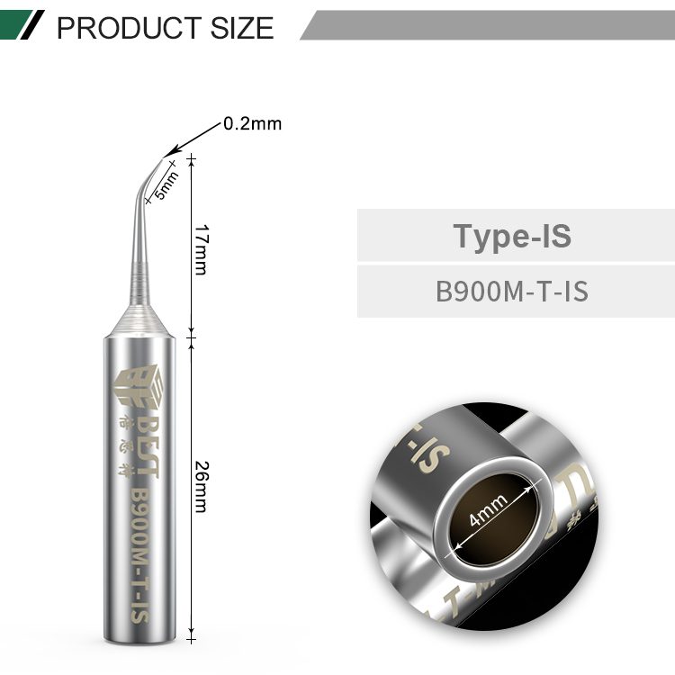
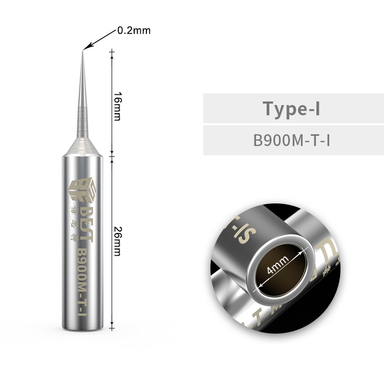
Specifications
- Model: B900M-T
- Weight: 41g
- Type: Lead-free soldering iron tips
- Point: 0.2mm
- Material: Oxygen free copper
What's in the box?
2 x Best soldering iron tips

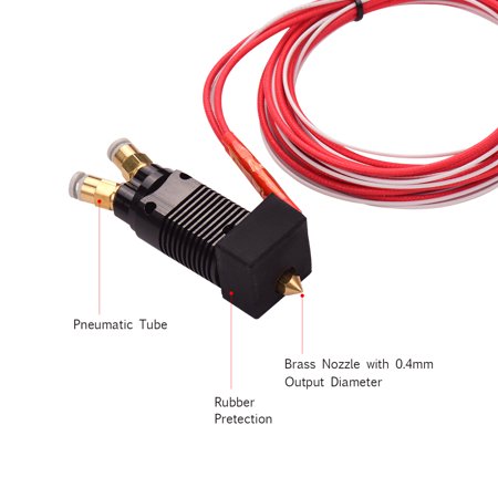
Description:
Dual color metal hotend extruder kit for CR-10 series Ender-3 3D Printer.
0.4mm nozzle; 1.75 filament size; aluminum heating block; heater wire 12V/24V for option.
Can access two lines of filament, switch between two input when printing, and extrude through one hot end.
Color switching is fast and stable, and print quality has no obvious defects.
The heating block and the heat sink are connected and fixed by two screws, making the print head more stable.
Specifications:
Colour: Black
Heat Sink Material: Aluminum Alloy
Heater Material:Aluminum Alloy
Nozzle Material: Brass
Pneumatic Connector Material: Stainless Steel
Voltage: 24V
Wire Length: Approx. 1400mm
Body Size: 80mm x 25mm x 22mm
What's in the box?
1 x Hotend Extruder Kit

The kit includes our Foundation Plate which attaches to your pi-top [4]. Plug components into the foundation plate and get started right away, following step-by-step tutorials to learn the basics of coding and physical computing. Then continue your learning by progressing into projects in advanced coding, robotics, cybersecurity, and AI.
What's in the box ?
You will need a pi-top [4] or an essentials kit to use our Sensor Foundation Kit.
The Sensor Foundation Kit includes:
|
|

Note: We have tested this unit successfully on Zero and Zero 2.
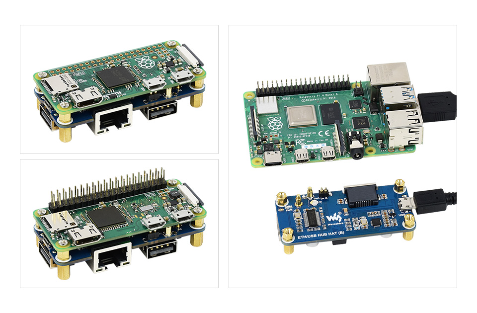
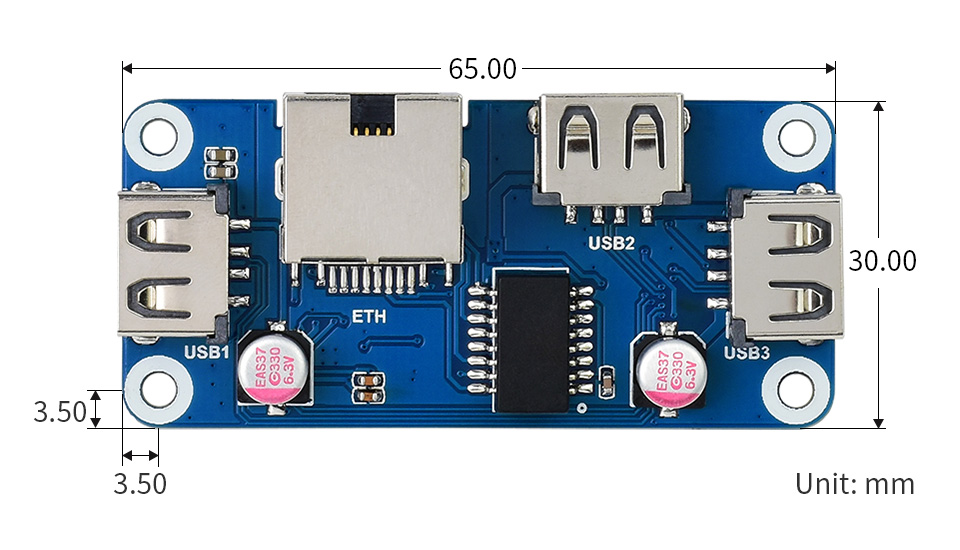
The ETH/USB HUB HAT (B) is an Ethernet and USB HUB designed for Raspberry Pi, providing 1x RJ45 Ethernet port and 3x USB 2.0 ports. It's pogo pin design is specialized for Zero series, while the onboard normal USB connector can be used to connect with other Raspberry Pi boards through a USB cable.
Specifications
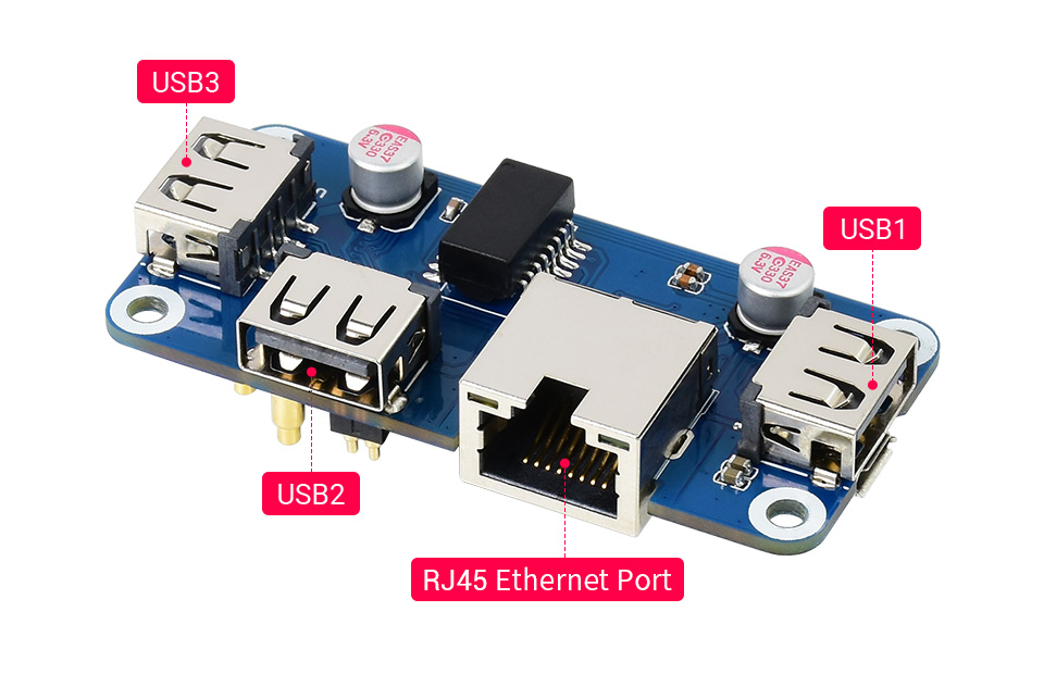
- 3x extended USB ports, compatible with USB 2.0 / 1.1
- Incorporates RTL8152B Ethernet chip, supports 1x RJ45 Ethernet port, 10/100M auto-negotiation
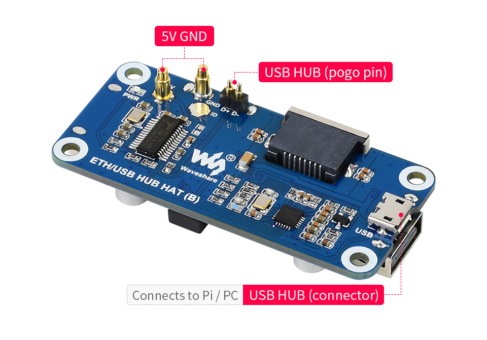
- Pogo pin design, for direct connecting with Raspberry Pi Zero/Zero W/Zero WH
- USB HUB connector, for connecting with Raspberry Pi 4B/3B /3A /2B through USB cable
What's in the box ?
1 x ETH/USB HUB HAT (B)
1 x Screws and standoffs pack
Resources
Wiki: ETH/USB_HUB_HAT_(B)

Description:
PGA2040 is a compact RP2040 breakout intended for the most svelte and embeddable of projects. It contains only the components necessary to run the RP2040 (that's the crystal, flash, regulator and essential support circuits) and it has no fripperies like LEDs, buttons and USB connectors - you'll need to attach your own USB connector to be able to program it.
The benefits of all this drastic pruning are a tiny, 21mm square footprint and lots of exposed RP2040 pins to play with! 30 of them can be used as general purpose I/O (that's four more I/O than on a Raspberry Pi Pico) and 4 are ADC-equipped. It also has the cutest little pin labels in the known 'verse, because space is tight on this board.
Header pins are sold separately - you can solder it to standard Pico pin headers (though bear in mind you'll need 48 pins if you want to populate it fully).
Like our other RP2040 boards, PGA2040 is programmable with C , MicroPython or CircuitPython - choose your fighter!
Specifications:
- Powered by RP2040
- Dual ARM Cortex M0 running at up to 133Mhz
- 264kB of SRAM
- 8MB of QSPI flash supporting XiP
- Crystal oscillator
- On-board 3V3 regulator (max regulator current output 300mA)
- 48 pins, arranged with 2.54mm (0.1") spacing in a Pin Grid Array
- 30 multi-function General Purpose IO (4 can be used for ADC)
- 8 GND pins
- Input voltage range 3V - 5.5V (on VB pin only)
- Measurements: approx 21mm x 21mm x 3mm (L x W x H)
- Schematic
- Eagle CAD part
What's in the box ?
1 x PGA2040
Getting Started :
PGA2040 is firmware agnostic! You can program it with C/C or MicroPython in the same way as you would a Raspberry Pi Pico. You can find (lots) more information on how to do that (as well as download links for the firmware/SDK) on the RP2040 landing page.
You can also use CircuitPython on your PGA2040! CircuitPython is an easy to use, well-established ecosystem with lots of example code and drivers for interfacing with different kinds of hardware. Click here to download the CircuitPython firmware for PGA2040 and click here for a getting started guide.
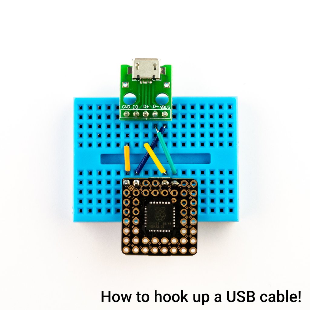
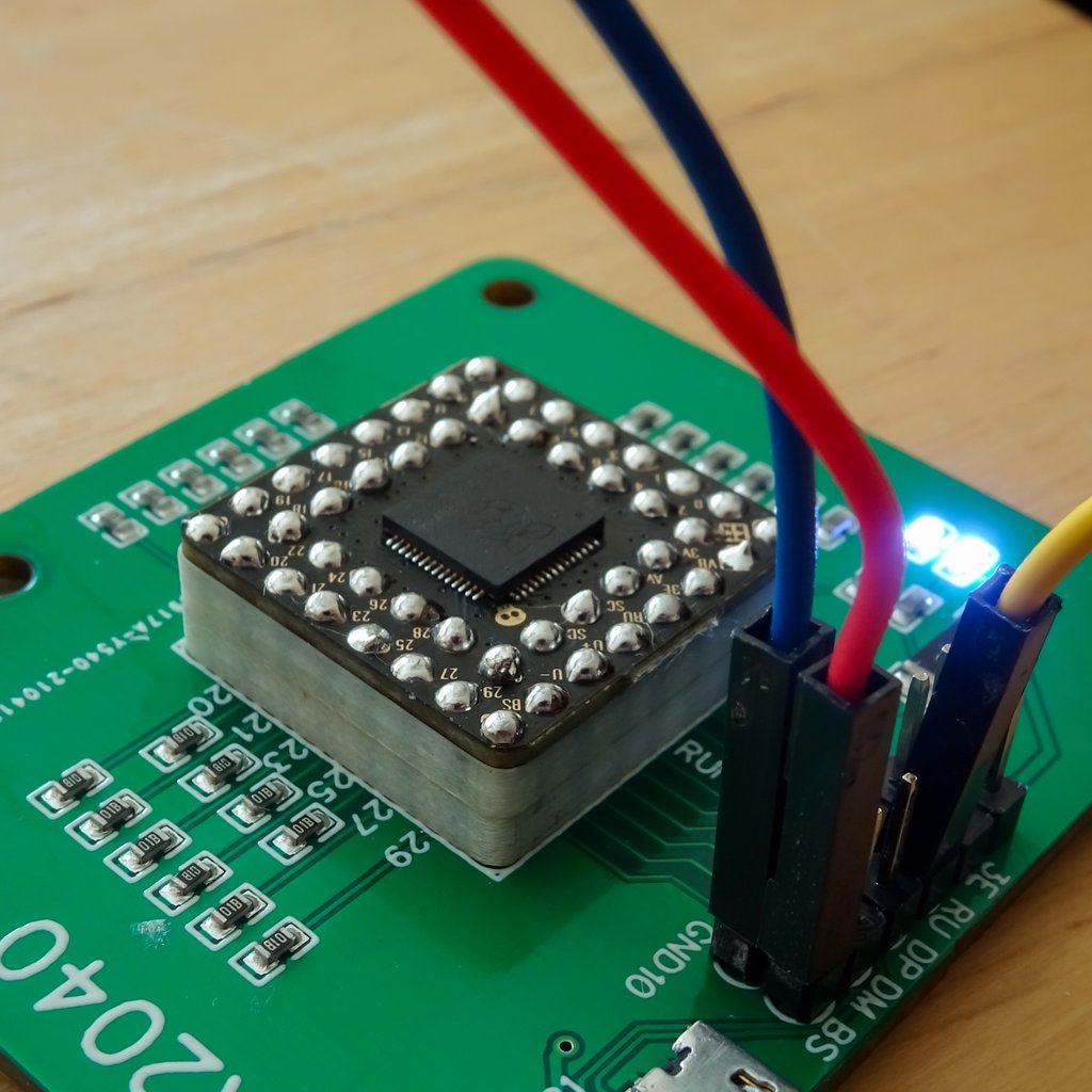
To program PGA2040 via USB you will need to hook wires up to VB, GND, U and U-. Make sure that the 5v only goes to VB on PGA2040, if it ends up elsewhere it will result in a bad time. A USB breakout board is a convenient way of getting at the wires in your USB cable, check out the extras tab for some options!
To get into BOOTSEL mode so you can flash firmware to your PGA2040, connect the BS pin to ground whilst plugging the USB into your computer.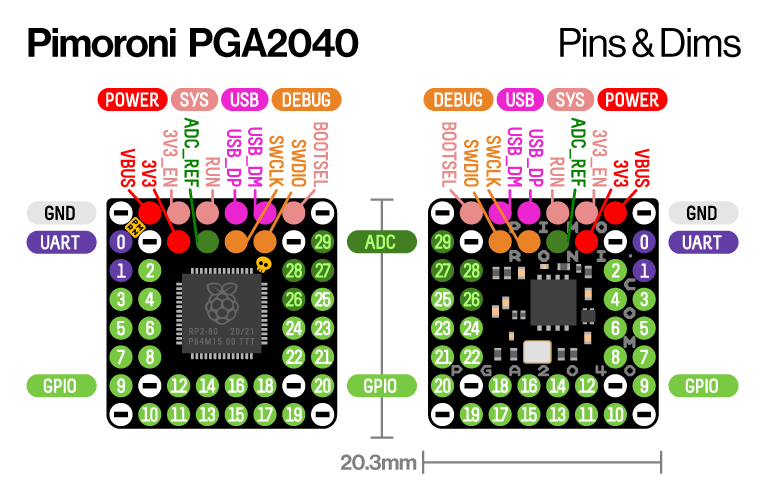
About RP2040
Raspberry Pi's RP2040 microcontroller is a dual core ARM Cortex M0 running at up to 133Mhz. It bundles in 264kB of SRAM, 30 multifunction GPIO pins (including a four channel 12-bit ADC), a heap of standard peripherals (I2C, SPI, UART, PWM, clocks, etc), and USB support.
One very exciting feature of RP2040 is the programmable IOs which allow you to execute custom programs that can manipulate GPIO pins and transfer data between peripherals - they can offload tasks that require high data transfer rates or precise timing that traditionally would have required a lot of heavy lifting from the CPU.

The MonkMakes Solar Experimenters Kit for micro:bit is a project kit that allows you to experiment with harvesting energy from the sun and other light sources. It consists of a solar panel to harvest the energy, a solar store that stores the harvested energy, and a low energy light bulb and a motor that can be driven with the energy that you harvest.
Specifications
There are three projects that introduce energy harvesting without the micro:bit, followed by 3 bigger projects that use the micro:bit (not provided) as an intelligent controller. The micro:bit monitors and manages the charging and discharging of the solar store.
With this project kit you will learn all about how tiny amounts of energy can be harvested from the sun and stored for later use, using a practical and experiment-led approach.
What's in the Box ?
1 x 10v Solar Panel
1 x Solar Store Board
1 x 3v LED light bulb
1 x Set of alligator clip leads (10 leads)
1 x Small motor with fan
1 x Booklet (A5)
Resources
- Instructions (PDF)
- Data Sheet (PDF)
Lessons Plans are available here: https://drive.google.com/drive/folders/1o5tRY1PeU4N-NSVctra4NxnCvmP65Huj

The MonkMakes Slider for micro:bit allows you to interact with your micro:bit by sliding a control left and right.
The board uses a 10kΩ linear variable resistor (pot) to output a voltage between 0 and 3V that can be measured in your micro:bit programs using one of the micro:bit connections as an analog input.
The kit includes the Slider for micro:bit itself plus a set of 5 alligator clip leads.
Specifications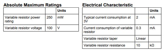
What's in the box ?
1 x 3v Slider
5 x crocodile clip leads
You might also need....
micro:bit not included
Resources
- Instructions (PDF)
- Data Sheet (PDF)
- Lesson Plans (Google file share)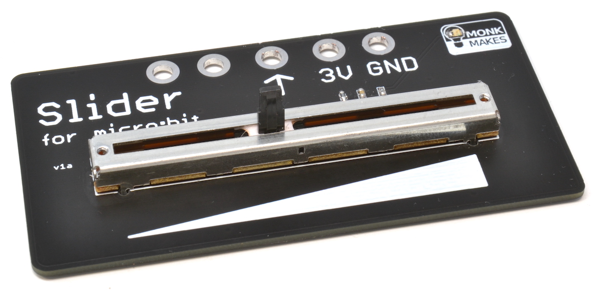
(* micro:bit not included)

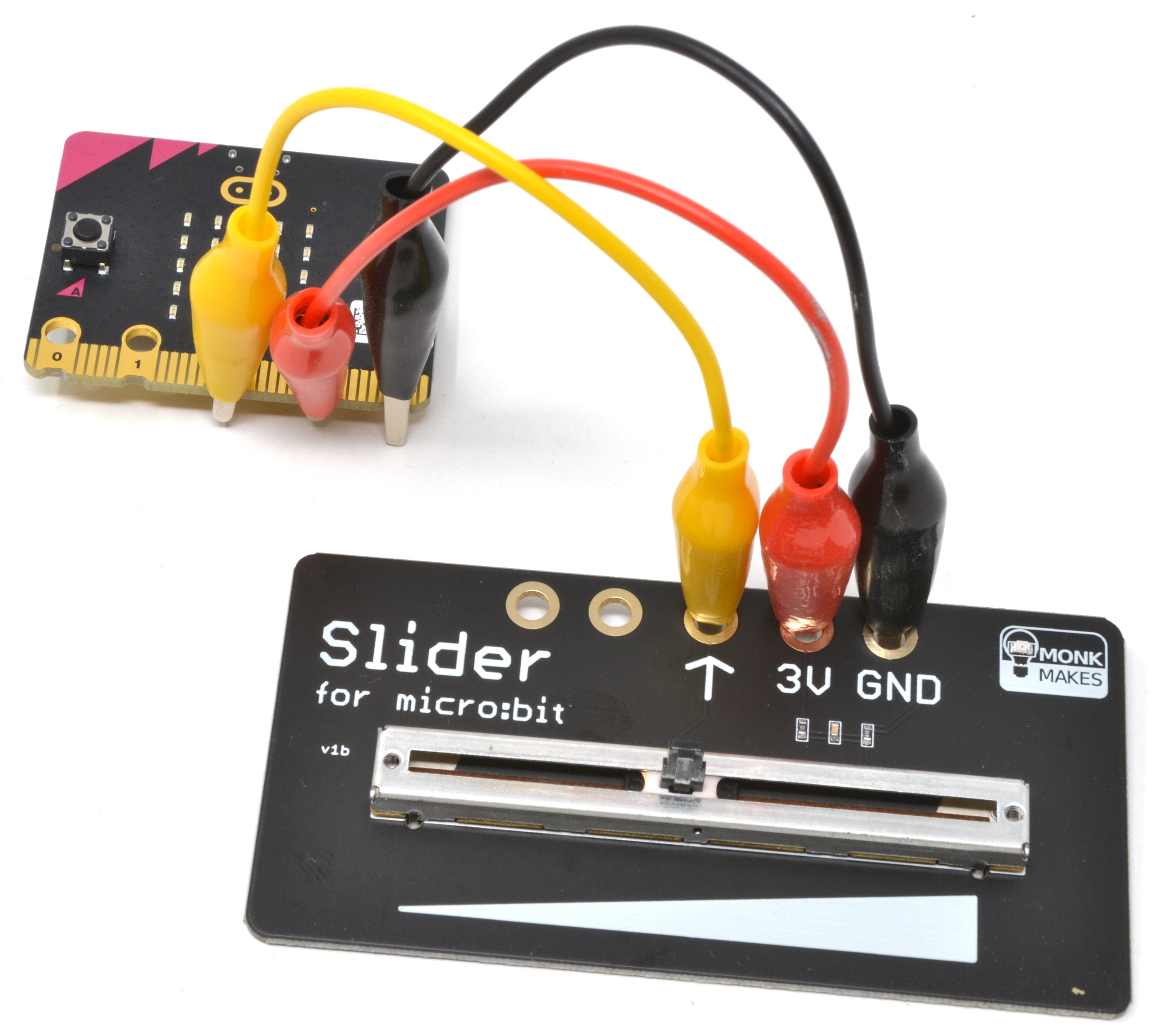
A LiPo battery and charger board that charges automatically while you use your micro:bit! This neat solution to your micro:bit’s power needs comes with an acrylic layer enclosure to protect your micro:bit and the Charger for micro:bit.
Features
- Program your micro:bit and charge at the same time
- Once charged the Charger for micro:bit can power your micro:bit for up to 20 hours using its rechargeable built-in LiPo battery
- Acrylic case to protect your micro:bit and Charger for micro:bit
- On/off switch
- Full charge indicator LED
Specifications
What's in the box?
6 x Acrylic pieces labelled 1 to 6
1 x Charger for micro:bit board with USB adapter fitted
4 x plastic nuts and bolts
Resources
- Instructions (PDF)
- DataSheet (PDF)

The 7-segment for micro:bit is a four digit 7-segment display for micro:bit. You can use it to display numbers, but it can also display letters and other characters, albeit with the limits imposed by the 7 segments of each digit.
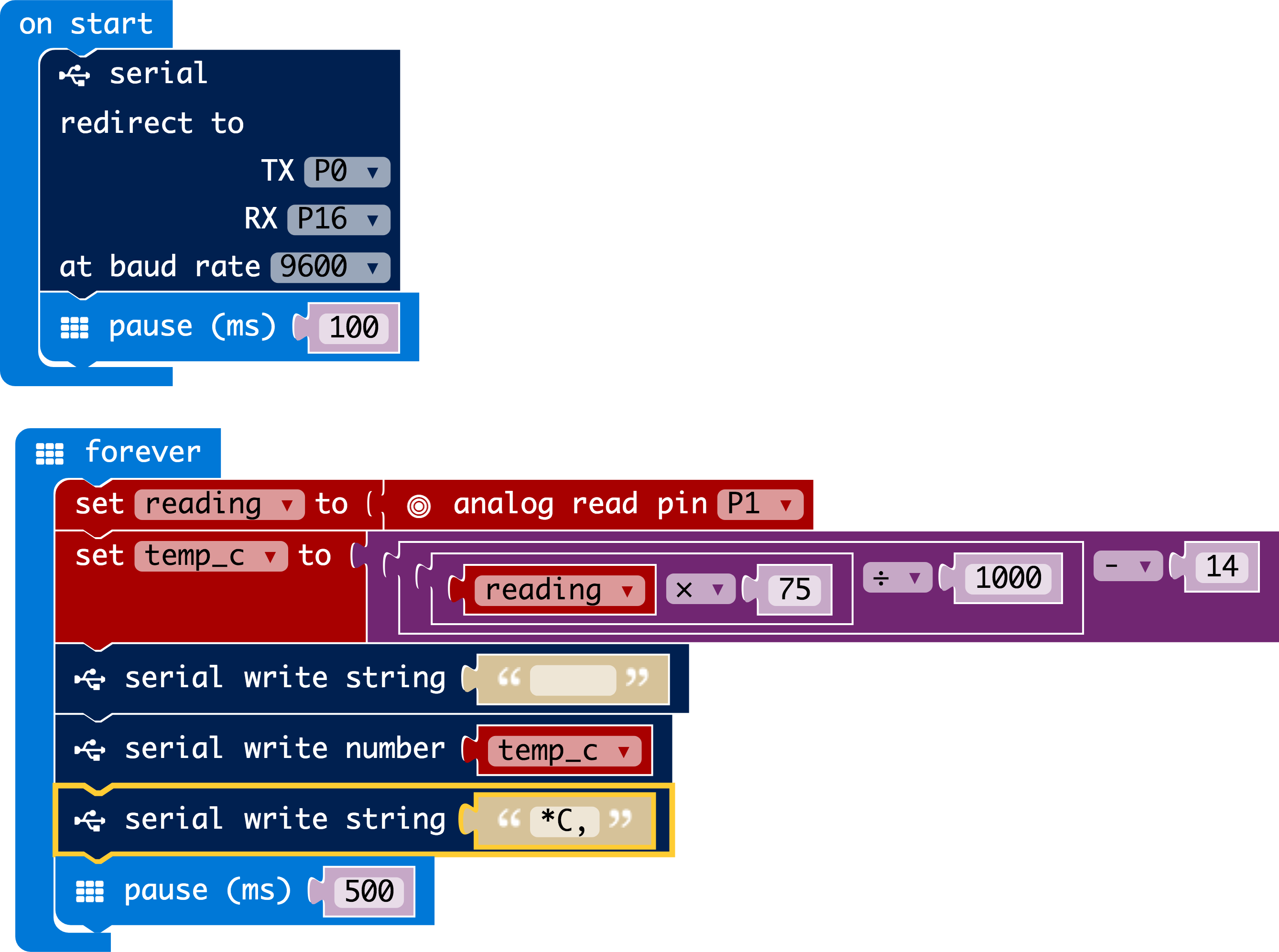
Powered directly from micro:bit pins it can be used to send messages to the display using the micro:bit’s Serial blocks.
Please note that this version of the 7-Segment for micro:bit uses a red LED display rather than the green display of earlier versions.
Specifications:
The 7-segment for micro:bit is a four digit 7-segment display for micro:bit.
You can use it to display numbers, but it can also display letters and other characters, albeit with the limits imposed by the 7 segments of each digit.
• Low power high brightness LEDs
• Serial interface using a single micro:bit pin
• ATTiny816 preloaded firmware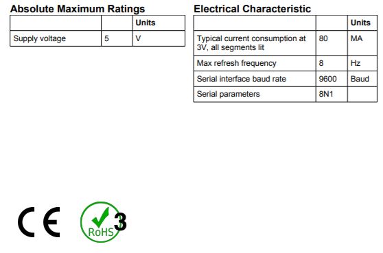
What's in the box ?
1 x 7-Segment for micro:bit
Resources:
Instructions (PDF)
Datasheet (PDF)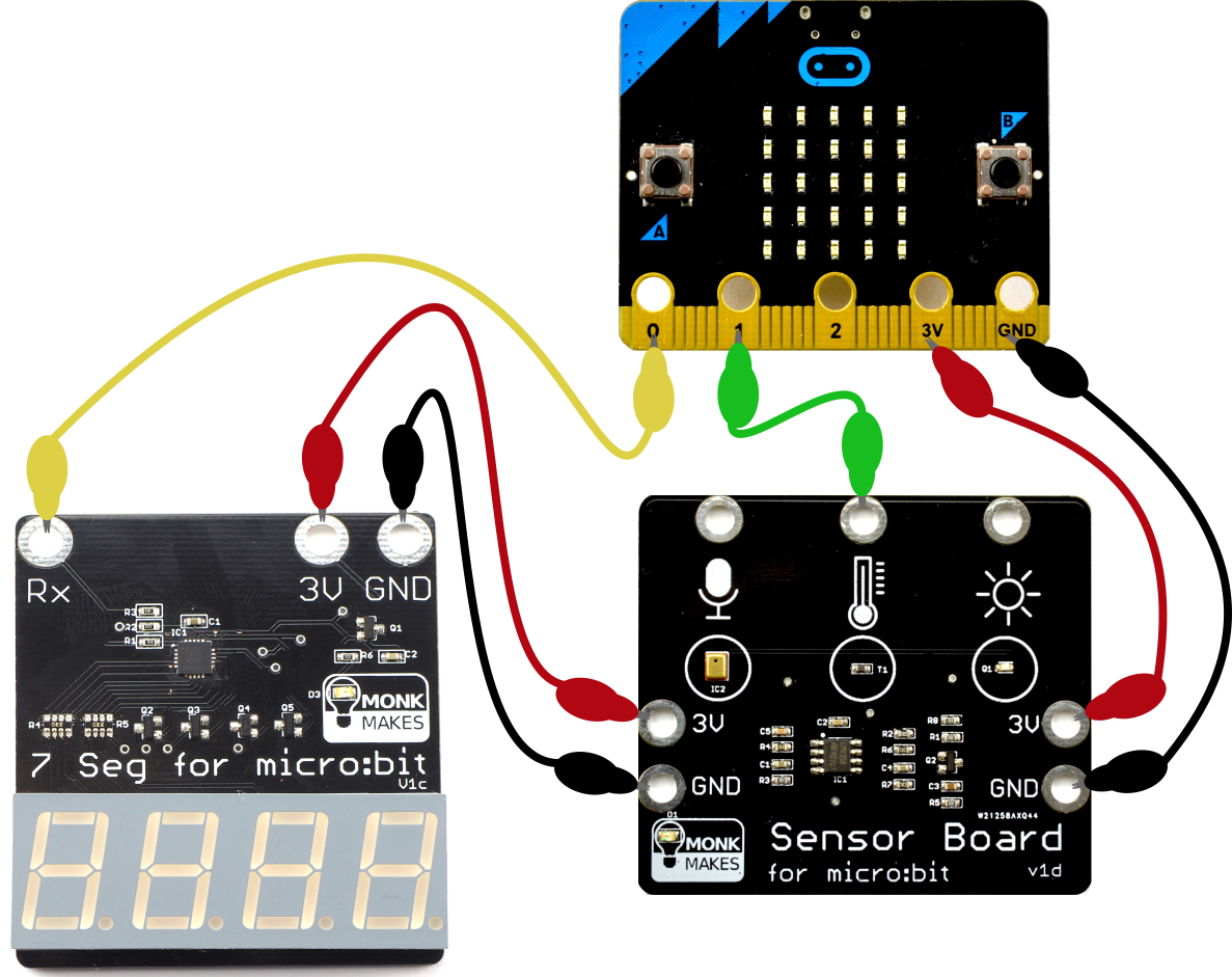
(* Micro:bit, Sensor board and jumpers NOT included*)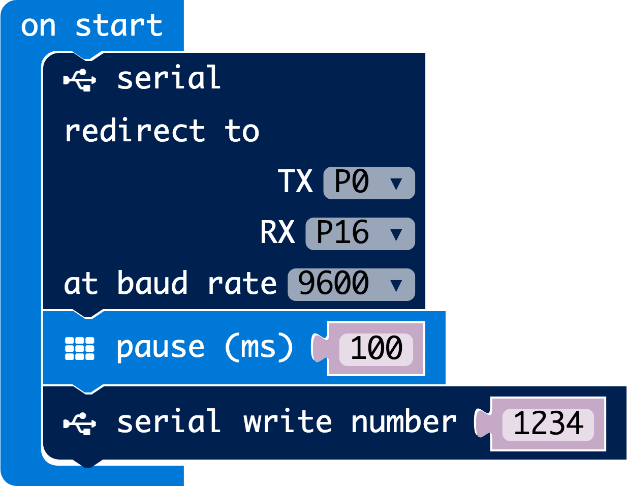

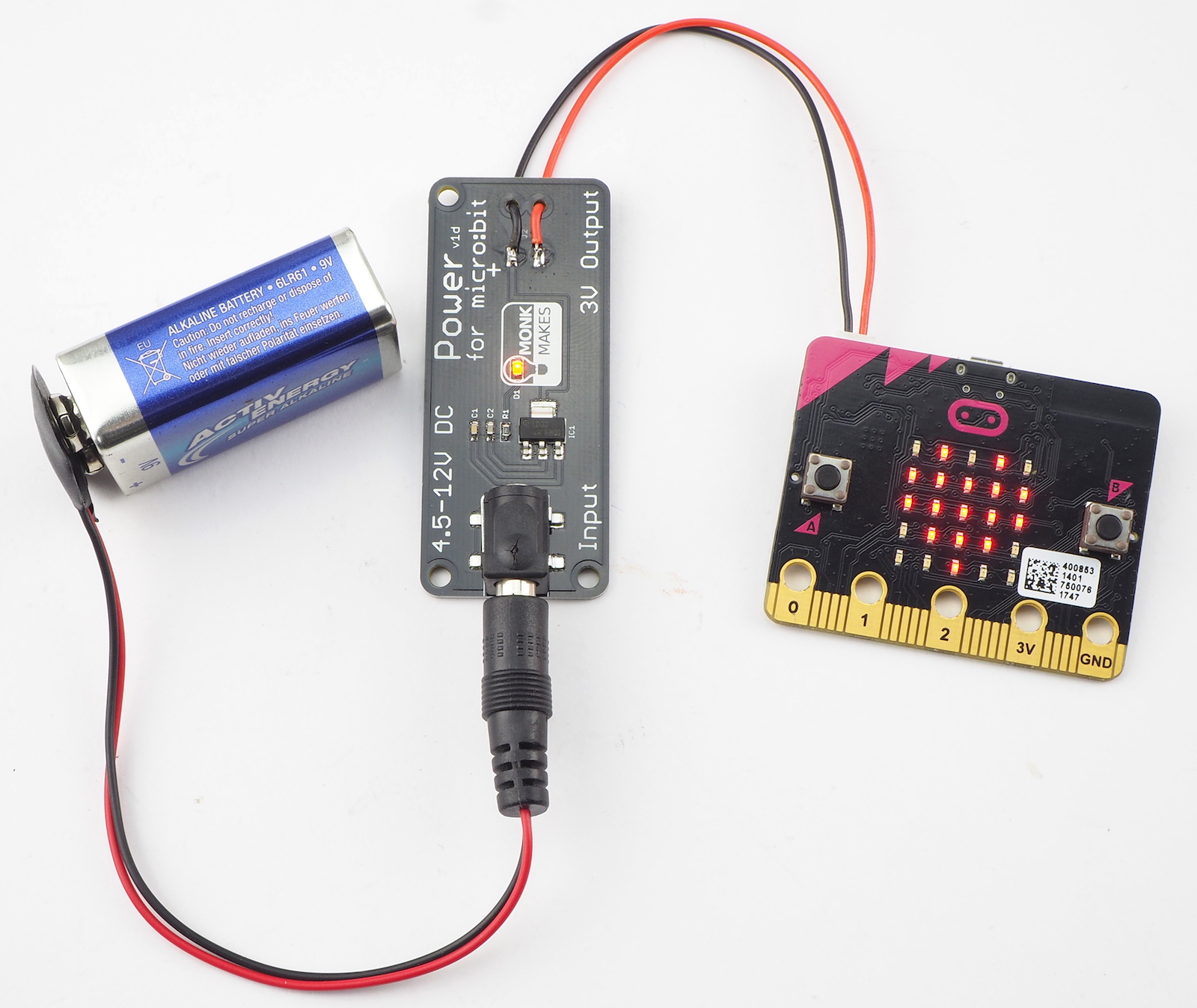
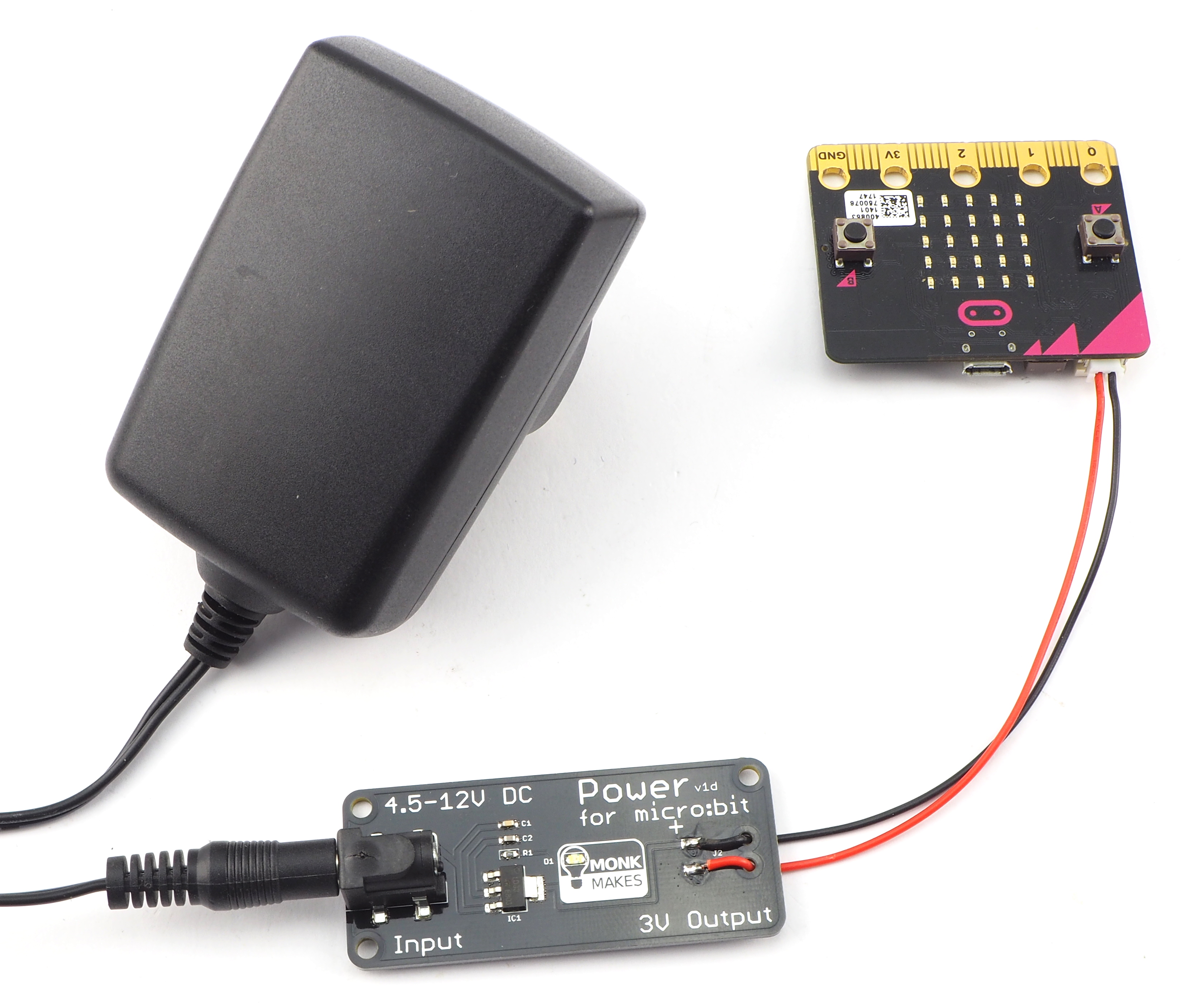
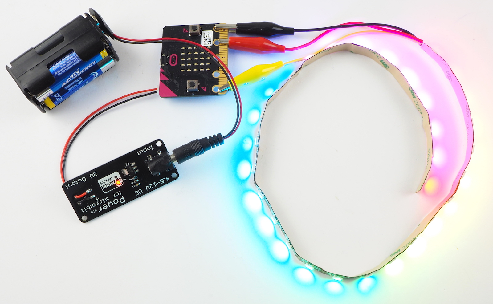
The MonkMakes Power for micro:bit opens up lots of ways of powering your micro:bit.
The board has a standard DC barrel jack that accepts between 4.5 and 12V and provides a regulated 3V output to the micro:bit via its JST battery connector.
Specifications: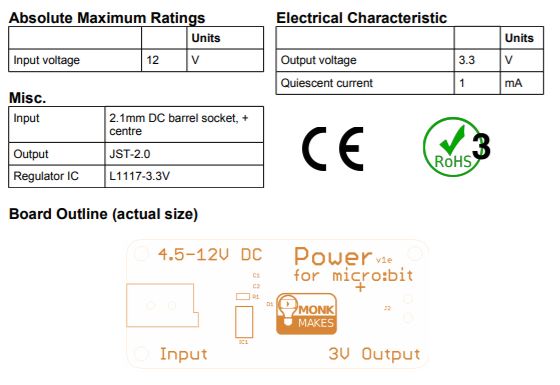
What's in the box ?
1 x power for micro bit board (*Batteries and micro:bit not included)
Resources:
Instructions (PDF)
Datasheet (PDF)